Note: Descriptions are shown in the official language in which they were submitted.
WO 94122681 ~ ~ PCTIJP94/00501
f
_ 1 _
p
DESCRIPTION
METHOD OF DETECTING A DEFLATED TYRE ON A VEHICLE
TECHNICAL FIELD
This invention relates to a method of detecting
a deflated tyre on a vehicle suitable for cars, trucks or
the like.
BACKGROUND ART
Prior applications such as French Patent
Publication No. 2568519 and European Patent Publication
No. 291 217 propose using wheel speed signals from the
vehicle wheels such as for example the signals from an
anti-lock braking system which are multi-pulse signals of .
typically 4 8 to 9 6 pulses per revolution of each wheel.
The prior art system compares the speed derived signals in
i
various ways, and also attempt to overcome errors due to
vehicle f actors such as cornering, braking, accelerating,
uneven or changing loads, which can cause changes in the
speed signals which are larger thar~ those . caused by a tyre
deflation of for example 0.4 bar.
French Patent Publication No. 2568519 avoided
errors of this type by monitoring the speeds of the
diagonally opposed pairs of wheels for a long time or
distance period so that it averaged out effectively
cornering of the vehicle. The result however was that the
device operated very slowly taking many Kilometres to
sense a pressure loss.
European Patent Publication No. 291 217 improved
the situation by calculating the lateral and longitudinal
acceleration of the vehicle using the same four wheel
speed signals and setting fixed limits above which the
detection ' system was inhibited to avoid false signals due
3 5 to cornering and acceleration. This inhibition of
detection however meant that for a proportion of the time
of vehicle running the system was not sensing punctures,
the actual proportion depending upon the type of roads and
s.
WO 94122681 ~ PCTlJP94lOOSOI
~,
_ _ I
_ 2 .
the way the vehicle was being driven.
The real difficulty with these types of systems ;
is that, apart from the lateral acceleration of the
vehicle which occurs during cornering causing increased 3
deflection of the outer pair of . ~ wheels compared to the '
inner pair of wheels, eacfi~~: vehicle has different
characteristics due to the position of the centre of
gravity and the type of suspension and these different
characteristics when cornering produce additional
deflections in the outer pairs of tyres with regard to the
inner pairs of tyres.
However the vehicle characteristics make the
tyre deflections different in each of the tyres. Similar
problems occur due to vehicle characteristics in the
d~ections in the front pair of tyres compared to the
rear pair when the vehicle brakes, and vice- versa when
the vehicle accelerates.
It is an object of the present invention to
provide a method of detecting a deflated tyre on a vehicle
which accommodates the above changes, avoiding false
signals and detecting deflation for substantially all the
time when the vehicle is running.
DISCLOSURE OF INVENTION
According to one aspect of the present invention
there is provided a method of detecting a deflated tyre on
a vehicle by comparing the rolling radii of the tyres by
means of comparing angular velocity speed signals from
wheel speed sensors one at each wheel characterised by
calculating an error value DEL' where .
DEL' - ~ (C1+C4)/2-(C2+C3)/2] X 100
(C1 + C2 + C3 + C4 )!4
3 5 where C 1, C2, C3 and C4 are angular velocity values f or
left-hand trout, right-hand front, left-hand rear and
right-hand rear wheels of the vehicle respectively,
determining a correction factor LAT, calculating a
WO 94/22681 ~ ~ ~ ~ ~ ~ ~ PCT/JP94I00501
i~
- 3 -
corrected error value DEL where
DEL = DEL' - DELCOR
wherein
DELCOR = ( A x LAT ) + ( B x LAT 2 )
wherein A and ~ B are vehicle related constants, and
operating a tyre warning indicator provided in the vehicle
to indicate that at least one tyre is deflated when it is
sensed that the magnitude of the corrected error value DEL
is in the range 0.05 to 0.5.
Preferably the tyre warning indicator is
operated when the magnitude of the corrected error value
is in the range 0,1 to 0.3.
The vehicle related constants A and B may have
values in the range -5.0E-? to +S.OE-7 and -4.0E-9 to
+4.OE-9 respectively.
The correction factor LAT is found by
calculating from the four angular velocity values Cl, C2,
C3 and C4 respective first, second, third and fourth
deciding factors (MC1, MC2, MC3, MC4) where
MC1 = C1
MC2 = C2/[ (C2 + C4)/(C1 + C3)]
MC3 = C3/[ {C3 + C4)/(C1 + C2)]
MC4 = C4/[ [ (C2 + C4)/(C1 + C3)] X [ (C3 + C4)/(C1 + C2)]]
summing the four deciding factors and multiplying this sum
by a centralising constant (K) to give a central deciding
factor (MPSD) and selecting the correction factor (LAT) as
follows, if the first or second deciding factor (MC1 or
MC2) is greater than the central deciding factor (MPSD)
then
LAT = 2 X (C3 ~- C4) x {C1 + C2 + C3 + C4),
if the third or fourth deciding factor (MC3 or MC4) is
greater than the central deciding factor (MPSD) then
LAT = 2 x (C1 - C2) X (C1 + C2 + C3 + C4),
or if none of the deciding factors {MCl, MC2, MC3 or MC4)
is greater than the central deciding factor (MPSD) then
LAT = (C1 + C3 - C2 - C4) x (C1 + C2 + C3 + C4).
The centralising constant used in the derivation
of the central deciding factor MPSD may be in the range of
wo 9anzssi pcTi,~aioosoi
.,
21~so72 _ _
4
0.250125 to 0.250625 and preferably has a value of -
j
0.25025.
The particular tyre which is deflated may be '
detected deflation
by
calculating
for
each
wheel
a
indicating
factor
IMC1,
IMC2,
IMC3
= .::and
IMC4
respectively
'
and en selecting the factor having the largest numerical
th
value, the deflation indicating v-_factors being calculated
as follows:
IMC1 C1
=
if the first deciding factor (MC1) is greater than the
centraldeciding factor (MPSD) then
IMC2 C2/[ ((C4/~C3)/2) + 0.5]
=
IMC3 C3/[ ((C4/C2)/2) + 0.5]
=
IMC4 C4/[ [ ((C4/C3)/2) + 0.5] x [ ((C4/C2)/2)
. = + 0.5]J;
if the second deciding factor (MC2) is greater than the
centraldeciding factor (MPSD) then
IMC2 C2/[ ((C4/C3)/2) + 0.5]
_
IMC3 C3/[ ((C3/C1)/2) + 0.5J
=
iMC4 C4/[ [ ((C4/C3)/2) + 0.5] x [ ((C3/Cl)/2)
= + 0:5]];
if the third deciding factor (MC3) is greater than the
centraldeciding factor (MPSD) then
IMC2 C2/[ ((C2/Cl)/2) + 0.5]
=
IMC3 C3/[ ((C4/C2)!2)~ + 0.5]
=
IMC4 C4/[ [ ((C2/C1)/2) + 0:5] x [ ((C4/C2)/Z)
= + 0.5]];
if the fourth deciding factor (MC4) is greater than the
centraldeciding factor (MPSD) then
IMC2 C2/[ ((C2/C1)/2) + 0.5J
=
IMC3 C3/[ ((C3/C1)/2) . + 0.5J
= -
r
IMC4 C4/[[ ((C2/Cl)/2) + 0.5] x [ ((C3/C1)/2)
= + 0.5]];
or if
none
of
the
deciding
factors
(MC1,
MC2,
MC3,
MC4)
is
greaterthan the central deciding (MPSD) factor then
IMC2 C2/[ (((C2 + C4)/(C1 + ,C3))/2) + 0.5] '
=
IMC3 C3/~(((C3 + C4)/(C1 + C2))/2) + 0.5J
=
IMC4 C4/['[ (((C3 + C4)/(C1 + C2))/2) + 0.5] x '
=
[ (((C2 + C4)/(C1 + C3))/2) + 0.5]].
Whilst the invention in , fact compares the
angularvelocities of the wheels it should be understood
that this can be done by comparing the times for one full
;,;
__ ~.._. . .. , _ .. , . . . . _ , _.._
,:. ..-. ,:: ... . .. -. :.-: ,:: . . . ,~: ..:.~. . >..
'~ ~ PCT/JP94100501
WO 94/Z2681
_
turn of each wheel or by comparing for
digital signals
multipulse wheel ;
speed generators.
To allow for tyres from different manufacturers
which may therefore be of different sizes an
5 initialisation procedure may be carried out. This
monitors the signals under normal driving conditionsand
enables constants be determined to allow
for each wheel
to
for variations.
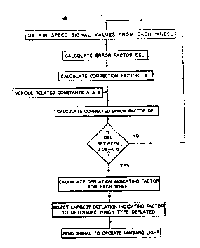
BRIEF DESCRIPTION OF DRAWINGS
Figure 1 is a schematic diagram showing a
deflation warning device for a car having four wheels;
- Figure 2 is a schematic diagram showing the
sequence of computations used to determine if a deflated
tyre exists and decide which one is deflated; and
Figure 3 is a schematic diagram showing the
sequence of computations used in determining the
correction factor LAT.
BEST MODE FOR CARRYING OUT THE INDENTION
Further aspects of the present invention will
become apparent from the followings description, by way of
example only, of one embodiment in . conjunction with the
attached diagrammatic drawings.
The . apparatus shown in Figure 1 provides a
deflation warning device for a vehicle .having four wheels
1, 2, 3 and 4. Wheels 1 and 2 are the left- and right-
4
hand front wheels respectively and wheels 3 and 4 are the
3
left- and right-hand rear wheels respectively. Each wheel
has a toothed wheel device associated. with it of the type
designed and fitted to provide a digital signal comprising
a magnetic pick-up of the type used for a vehicle anti-
skid system of the electronic type-often commonly known as
ABS braking system. ~ Each pick-up is additionally
connected . in this case to a deflation warning detection
system which uses the same digital signal as the ABS
system.
The electronic signals from each of the four
WO 94!22681 21 ~ 6 0 ~ ~ PCTIJP94/00501
- 6 -
wheels are carried through cables , 5 to four separate
inputs 6, 7, 8 and 9 of a central processing unit 10.
Four separate indicator lights 12, 13 14 and 15 are
provided one for each wheel I, 2~~ 3 and 4. Thiese
indicator lights may be most conveniently mounted on the °
vehicle dashboard.
The central processing unit 10 is basically a
microprocessor which monitors the four signals and
compares them to determine if an outward signal is to be
sent to operate an indicator light to warn of a deflated
tyre. In the case where the vehicle already has an ABS
system fitted then the microprocessor I 0 may be the same
microprocessor as the ABS system. Alternatively a
separate microprocessor may be provided:
The respective values of the total digital pulse
signals from each of the wheels 1, 2, 3 and 4 in a five
second period are C1, C2, C3 and C4 respectively. The
central processing unit 10 computes these frequency values
as will be described below to determine whether or not to
send a deflation warning signal to one of the warning
lights 12, 13, 14 or 15. ~~ .
The sequence of operations used in this
computation is shown schematically in Figure 2.
The first operation in the method of the
invention is to calculate from the actual wheel speed
values CI-C4 an error value DEL' where
~ (C1+C4)/2-(C2+C3)!2] x 100
DEL' - C4)/4
(C1 + C2 + C3 +
However because the actual wheel speed values
may be distorted due to vehicle such as cornering, '
factors
braking, accelerating or uneven
loads which give rise to a
greater effect than that caused tyre deflation it is
by a
necessary to correct this calculated
error value
to remove
these vehicle effects.
To correct the error value DEL' a correction
factor LAT is calculated according the magnitude of
to
CA 02136072 2001-05-29
7
respective deciding factors MCl-MC2 for each wheel in comparison to a central
deciding factor MPSD. The central deciding factor is equal to the sum for the
four
deciding factors MC1-MC2 multiplied by a centralising constant K which in this
embodiment is selected to be 0.25025. The value of the correction factor LAT
is then
calculated depending on which if any of the four deciding factors MC1-MC4 is
greater in magnitude than the central deciding factor MPSD as follows:
if MC 1 or MC2 > MPSD
then LAT - 2 x (C3 - C4) x (C 1 + C2 + C3 + C4)
or if MC3 or MC4 > MPSD
then LAT - 2 x (Cl - C2) x (C1 + C2 + C3 + C4)
otherwise LAT = (Cl + C3 - C2 - C4) x (C 1 + C2 + C3 + C4).
This sequence of operations is shown in Figure 3.
The calculated error value DEL' is then corrected to remove vehicle effects to
give a corrected error value DEL according to the following equation:
corrected error factor DEL = error factor DEL' - DELCOR
wherein DELCOR = (LAT x A) + (LATZ x B) wherein A and B are vehicle
related constants which allow for vehicle factors such as the track and other
dimensions of the vehicle and characteristics of the suspension particularly
in relation
to side-to-side tilt. The values of these constants A and B for a particular
vehicle may
be determined by experiment. Values of the constants which have been
established
for various cars are shown below in Table 1.
TABLE 1
Vehicle Year Constant A Constant
B
Audi 100 1992 -1.8E-07 -6.2E-10
BMW 850i 1992 -+-I.OE-07 +4.6E-10
Peugeot 1992 -3.3E-08 -1.8E-10
405
Rover 820SLi1992 -~1.4E-07 -1.4E-09
Determination of constants A and B
The constants A and B are obtained by carrying out a running test with respect
to a sample car under normal tire pressure with varying lateral gravity (G) of
the
sample car; plotting values of LAT and DEL at each lateral gravity; and
regressing the
plots by the following quadratic which passes through the origin
DEL' _ (A x LAT) + (B x LATZ)
wherein LAT = (Cl + C3 - C2 - C4) x (Cl + C2 + C3 + C4)
DEL'
LAT
CA 02136072 2001-05-29
7a
Determination of centralising constant K
The centralising constant K is determined according to sensitivity of a tire
to
be attached to a wheel to deflation. For example, in the case of a tire whose
tire
angular velocity increases 0.1 %, the centralising constant K is calculated as
follows:
K - (I + 0-11 ) / 4 = 0.25025
100
WO 94122681 PCTIJP94/00501
213607
---.:
_g_
Having calculated the corrected error value DEL ,
the central
processing
unit
then
decides
if the
value
i
of DEL is in the range of 0.05 to 0~.5'v which indicates the '
presence
of a
deflates
tyre.
t
5 Values of DEL below 0.05' .are the result of minor
statistical
variation
in the
counts
from
each
wheel
whereas values of DEL greater than 0.5 indicate a
relatively
uncommon
occurrence
such
as wheel
spin
or a
locked wheel and are greater than the effect of a
10 punctured
tyre.
If the central processing unit 10 finds that the
_ corrected
error
value
is between
0.05
and
0.5
then
the
method of the invention moves on to the next stage which
is to determine which tyre is deflated. Otherwise the
system continues to monitor wheel speeds.
To determine which tyre is deflated the central
processing
unit
10 calculates
for
each
wheel
a deflation
indicating
factor
IMC1-IMC4.
These
factors
are
calculated
according
to the
following
procedure:
IMC1 C1
=
if the first deciding factor (MC1~ is greater . than the
,centraldeciding factor (MPSD) then
IMC2 C2/[ ((C4/C3)/2) + 0.5]
=
IMC3 C3/[ ((C4/CZ)/2) + 0.5] .
=
IMC4 C4/[ [ ((C4/C3)/2) + 0.5] X [ ((C4/C2)/2) + 0.5]];
_
if the second deciding factor (MC2) is ~ greater than the
central deciding factor (MPSD) then
IMC2 C2/[ ((C4/C3)/2) + 0.5]
=
IMC3 C3/[ ((C3/C1)/2) + 0.5]
=
IMC4 C4/[[ ((C4/C3)/2) + 0.5] x [ ((C3/C1)/2 + 0.5)]];
=
if the third deciding factor (MC3) is greafer than the
central deciding factor (MPSD) then '
IMC2 C2/y((C2/CI)/2) + 0.5]
=
IMC3 C3/[-((C4/C2)/2) + 0.5]
=
IMC4 C4/[ [ ((C2/C1)/2) + 0.5] x [ ((C4/C2)/2) + 0.5]];
=
if the fourth deciding factor (MC4 ) is ~ greater than the
central deciding factor (MPSD) then
WO 94122681 PCTIJP94/00501
. _2136072
_ 9
IMC2 .= C2/[ ((C2/Cl)/2) + 0.5] ; ,:
IMC3 = C3/[ ((C3/C1)/2) + 0.5] ~ ~ ; ,
IMC4 = C4/[[ ((C2/C1)/2) + 0.5] x [ ((C3/C1)/2) + 0.5]];
or if none of the deciding factors (MC1, MC2, MC3, MC4 ) is
greater than the central deciding (MPSD) factor then
IMC2 = C2/[ (((C2 + C4)/(C1 + C3))/2) + 0.5]
IMC3 = C3/[ (((C3 + C4)/(C1 + C2))/2) + 0.5]
IMC4 = C4/[[(((C3 + C4)/(C1 + C2))/2) + 0.5] X
[ (((C2 + C4)/(C1 + C3))/2) + 0.5]].
Thus having obtained a deflation indicating
factor for each of the four wheels the central processing
unit compares these to determine which wheel has the
factor of the largest magnitude. A signal is then sent to
operate the indicator light corresponding to that wheel in
order to alert the driver that the tyre concerned has
deflated. In a preferred arrangement the warning signal
is only sent after three sets of deflation indicating
factors, calculated from successive sets of wheel speed
! ;
data, all indicate that a particular tyre is deflated.
Whilst the above embodiment has illustrated the
method of the invention using the signal data from a
multi-toothed wheel system typically producing 48 or 96
pulses per wheel revolution the invention can equally be
used with other wheel speed sending systems. For example
the method may be used with a simple system which uses a
single pulse per revolution to compute the time period for
one rotation of each wheel, in which case it will be
necessary . to multiply the wheel speeds by a constant
factor to obtain data in the necessary form
Furthermore whilst the method of the invention
has been illustrated by reference to the , aforementioned
values of constants A and B related to specific vehicles,
values of constants A and B in the ranges of -S.OE-7 to
+5.0E-7 end -4.OE-9 to +4.OE-9 respectively have been
found useful in the invention. Values of A and B in the
ranges -2.OE-7 to +2.OE-7 and -2.OE-9 to +1.OE-9 have been
found particularly useful in practise of the invention. .
WO 94/?.2681 PCT/JP94/00501
X13607 2 .
_ ~'-',
- to -
INDUSTRIAL APPLICABILITY
Accordin to a method of the present invention,
difference of tyre deflections in each of the tyres due to
vehicle characteristics can be a~~ommodated to avoid false
signals. Deflation for substantially all the time when - ,
the vehicle is running can be_;~detected. The method can be
widely applied to vehicles such as cars and trucks.
,.