Note: Descriptions are shown in the official language in which they were submitted.
CA 02136189 2003-11-21
APPARATUS FOR THE TREATMENT OF
THORACIC DEFORMITIES SUCH AS SCOLIOSIS
This invention relates to apparatus for the treatment of diseases and symptoms
evidenced as deformities in the human skeletal systems and particularly for
the treatment of
scoliosis.
The human spine is a system which consists of a succession of vertebral bodies
which, in its normal state, extends within and defines a single sagittal
plane. Ideally, there
should be substantially no deviation in the frontal plane (perpendicular to
the sagittal plane
from a straight line. Within the sagittal plane, a certain degree of lumbar
lordosis and thoracic
kyphosis is normal and desirable. An excess degree of lumbar curvature is
known as
hyperlordosis, while an abnormally flat lumbar succession of vertebral bodies
is known as
hypolordosis. In like manner, hyperkyphosis (most commonly seen in
Scheuermann's
disease) is that condition evidenced by a greater-than-normal degree of
curvature in the
thoracic spine which gives a hump-back type appearance.
1 S Scoliosis may be defined as lateral deviation and rotation of a series of
vertebrae from
the midline anatomic position of the normal spine axis. The deformity occurs
in three planes -
frontal, sagittal and transverse. Scoliosis, in its more severe embodiments,
is a debilitating, if
not deadly disease. With the progression of the curve, structural changes
occur in the
vertebrae and in the formation and contour of the rib cage. This, in turn,
often threatens
respiratory function and capacity. The curvature of the spine itself can pose
danger to the
spinal cord. Still further, the interrelationships between other thoracic and
abdominal organs
are changes and the normal function thereof is imperilled. Fully 80% of all
scoliosis cases are
idiopathic, i.e. the cause is cause unknown.
There is no present "cure" for scoliosis as such, but treatments of the
symptoms have
been known for some time -- treatments with often-times questionable
effectiveness, inherent
intra-surgical danger to the patient, frequent patient discomfort and/or
substantial
inconvenience, and substantial likelihood of post-operative complication.
Non-surgical control of scoliosis (as distinguished from correction) is
available. Such
non-surgical treatments include physical therapy, biofeedback, electrical
stimulation and
orthosis (the Sayre cast, the Hibbs and Risser casts, the Milwaukee brace, the
Boston brace
and the Wilmington brace, for example). Reportedly, however, these non-
surgical methods
can collectively boast, at most, only a 70% success rate in arresting fiarther
progression of
CA 02136189 2003-11-21
scoliosis in cases of proven curve progression in growing (relatively
immature) spines. Many
of these non-surgical methods are contraindicated in cases involving
curvatures greater than a
specific range (usually about 40 degrees), certain patients with physical
infirmities in addition
to the scoliosis, patients with certain remaining growth potential, and/or
with patients who
cannot be reasonably expected to rigorously follow a prescribed therapeutic
regimen or to
emotionally tolerate the limitations and appearances of the various braces.
Surgical intervention in the correction of scoliotic curvature presently
involves spinal
instrumentation and spinal fusion first pioneered by Hibbs, et al (see Hibbs,
RA, Risser, JC
and Ferguson, AB: "Scoliosis treated by the fusion operation." J. Bone Joint
Sure., 6:3,
1924). One without the other is generally viewed as ineffective under current
convention. The
over-all objective of the surgical intervention is to correct the scoliosis as
much as is possible,
and to restore compensation of the spine with a symmetrical trunk and with
head, neck and
shoulders centered over the pelvis; and to stabilize the spine and prevent
curve progression.
The objective of the spinal instrumentation portion of surgical treatment of
scoliosis is to
immediately correct curvature to the degree possible and to immobilize the
spine in the
corrected orientation until a solid fusion has taken place.
Problems abound with currently available spinal instrumentation. Some
instrumentation occupies space needed for the bone graft placed over the
posterior spine.
Also, the attachment means used for spinal instrumentation inherently risks
intraoperative
spinal cord damage with the potential for irreversible paralysis. Still
further, many spinal,
instrumentation systems are prone to disengagement because their attachment
schemes
involve screws (prone to disengage from atrophic vertebrae) or hooks which
only partially
encircle vertebral body projections (prone to dislodging during movement).
"Harnngton Instrumentation" (see Harrington, P.R.: Treatment of Scoliosis.
Correction and internal fixation by spine instrumentation. J. Bone Joint
Sure., 44-A:591,
1962, and also Harnngton, P.R.: Surgical instrumentation for management of
scoliosis. J.
Bone, Joint Sure., 42-A:1 448, 196.) is the posterior spinal instrumentation
by which all
current systems are compared. In this system, bone-purchasing hooks are
attached to
posterior elements of the spine facets, laminae, and transverse processes.
Through these
hooks, distraction forces are applied to the concave side of the spinal curve
by the ratchet
principle, and compression forces are applied on the convex side of the
thoracic curve at the
base of the transverse processes and adjusted by the threadnut principle.
-2-
DC1: 359153.1
CA 02136189 2003-11-21
Despite its prominence, the Harnngton system has drawbacks: (1) failure of
derotation of the spine as the distraction force straightens the lateral
curvature; as a result the
rib hump is not corrected; (2) the distraction forces of the Harrington
instrumentation flatten
the spine with the result that the normal lumbar lordosis is obliterated
thereby producing a
marked deformity; (3) Harrington instrumentation does not provide enough
stability to the
spine and, therefore, postoperative immobilization is required in the form of
a cast or spinal
orthosis; (4) the bulky nature of the Harnngton instrumentation is such that
it protrudes well
beyond the normal dorsal contour thereby "tenting up" the overlying skin and
causing
breakdown problems; and (5) Harnngton instrumentation does not accommodate
growth in
cases of implantation in children; and (6) direct exposure of the spinal
components to any
spinal instrumentation often promotes inadvertent spinal fusion.
A relatively new system (the Cotrel-Dubousset (C-D) Instrumentation -- see
Cotrel,
Y. and Dubousset, J.: New Segmental posterior instrumentation of the spine.
Orthop. Trans.,
9:118, 1985) is a segmental spinal instrumentation that addresses many of the
Harrington
system's shortfalls. Nevertheless, C-D instrumentation exhibits its own
shortcomings, the
principle one being that it is complex and cumbersome, with too many "moving
parts". Also,
implantation is extremely complex and requires the skills and experience
possessed by few
practitioners. It obscures the posterior spine; limiting the amount of bone
graft surface for
biologic fusion.
One current form of anterior segmental instrumentation for treatment of
scoliosis is
the Zielke instrumentation (see Zielke, K. and Pellin, B.: Neue Instrumente
and Implantate
zur Erganzung des Harrintson Systems. Z Orthop. Chirl, 114: 534, 1976). This
system,
however, obviously involves accessing the anterior surfaces of the spinal
column to attach
instrumentation. This, in turn, carnes a significant risk of neural and
vascular injury with the
accompanying risk of partial or total paralysis.
The history of scoliosis and its treatment yields as its less on a seeming
paradox: it is
dangerous (and often ineffective) to treat the spine in addressing spine
anomalies. This
paradox has heretofore remained unsolved for two primary reasons: (1) the
causation and
mechanisms of scoliosis are not understood and, therefore, cannot be addressed
in a
preventative or even curative manner; and (2) direct management of an affected
system (in
this case the spine) is the traditional approach common to virtually all
orthopedic procedures,
a predisposition which yields a myopic view of the possible remedies as
evidenced by the
spinal instrumentation of the prior art.
-3-
DCI: 359153.1
CA 02136189 2003-11-21
The Applicant has already taught, in his U.S. Patent No 5,092,889, the design
of a
prosthetic rib which is adjustable in length and comprises three principal
components, that is
a rib sleeve carriage attachment, a rib shaft/rib shaft carriage attachment
and a rib sleeve. The
effective length of the prosthetic rib is determined by the degree to which
the rib shaft is
telescopically received within the rib sleeve, a lock being used to secure the
rib shaft and the
rib sleeve together after telescopic adjustment to provide a desired length
for the prosthetic
rib. The rib shaft and rib sleeve are formed whereby they jointly define a
single arc having a
constant radius of curvature regardless of the degree the rib shaft is
received within the rib
sleeve. This radius of curvature may be adjusted in the manufacturing process
according to
the expressed preference of the responsible surgeon, as dictated by the
physiology of the
intended recipient. The rib sleeve carnage attachment and the rib shaft
carriage attachment
are each formed as a pair of rods which are manipulated by the surgeon to
encircle the
appropriate human rib.
This prosthetic rib is implanted, in a position spaced laterally from the
spine, to span
between existing natural ribs thereby compensating for an abnormal absence of
intervening
ribs.
Applicant's U.S. Patent No. 5,092,889 therefore teaches a prosthetic rib
comprising a
first element having a first attachment means for attachment to a first human
rib and a second
element telescopically received within a portion of the first element and
having a second
attachment means for attachment to a second human rib.
The present invention is concerned with the provision of apparatus for the
treatment
and management of thoracic deformities such as scoliosis through manipulation,
not of the
spine, but of the adjacent ribs. Such apparatus is hereinafter referred to as
a "thoracodorsal
distractor" and comprises a telescopically expandable strut which is
attachable at a first of its
two ends to an upper thoracic human rib immediately adjacent to the spine and
at the second
end to a lower human rib adjacent to the spine.
According to the present invention, an apparatus for attachment between human
ribs
is a thoracodorsal distractor having a first upper length of the distractor
contoured to define a
first radius of curvature, and a second lower length of the distractor
contoured to define a
second radius of curvature which is larger than the first radius of curvature.
In this manner
the thoracodorsal expander is contoured for initially conforming to a merely
slightly
corrected scoliotic deformity and thereafter, through successive adjustments,
for defining and
imposing upon the patient's dorsum a substantially normal dorsal contour from
the thoracic
-4-
DC1: 359153.1
CA 02136189 2003-11-21
to the sacral segments thereof. The thoracodorsal distractor thereby defines a
contour in the
sagittal plane which exhibits a complex curve. Consistent with the curvature
defined by the
trough or "posterior gutter" which is collectively defined by the ribs'
arcuate deviation lateral
to the spinal column and medial to posterior angle of each rib, the upper
portion of the
thoracodorsal distractor which is to overlie the upper thoracic ribs defines a
curvature in the
sagittal plane of a smaller radius than that of the remaining extent (the
lower portion) of the
distractor which is to overlie the more lower thoracic and the lumbar regions
of the dorsum.
The upper portion of the distractor is of a fixed length and contour, while
the lower portion is
telescopically adjustable to expand and contract within a single arc of
curvature of
substantially larger radius than that of the upper portion.
Each attachment means may comprise at least one rod affixed at the outer end
of the
respective element, each rod being made of malleable material and being of a
length whereby
it may be manipulated to loosely encircle a human rib. Alternatively each
attachment means
may comprise a pair of rods affixed at the outer end of the respective
element, each pair of
rods being made of a malleable material and being of a length whereby they may
be
manipulated to loosely encircle a human rib. The first attachment means may
comprise first
and second members which are relatively movable between a first position in
which they
define a closed circle of a size for loosely encircling the human rib and a
second position in
which they define a broken circle having a breach of sufficient size to admit
the upper human
rib.
The distractor may further comprise locking means for selectively arresting
telescopic
movement between the first element and the second element at each of a
plurality of post-
operatively selectable positions. A rib sling may be provided for attaching a
medial portion of
the apparatus to a third human rib underlying the medial portion and for
forcibly drawing a
portion of the third rib to a position adjacent to the apparatus. A rack and
pinion system may
be operatively arranged to react between the first and second elements to
adjust the spacing
between the first and second attachment means. The pinion is preferably
removable after the
spacing has been adjusted.
A locking means is preferably arranged to lock the first and second elements
together
after the spacing between the first and second adjustment means has been
adjusted. This
locking means may either be a ratchet mechanism which inhibits contraction of
the distractor
whilst allowing its extension, or may be a locking disc arranged to lock the
first element to
the second element at each of a plurality of post-operatively selectable
positions.
-5-
DC1: 359153.1
CA 02136189 2003-11-21
One mode of using the thoracodorsal distractor involves placement of two
distractors,
one on either side of the scoliotic spine. One distractor is to act as a
distractor (on the concave
side of the curvature), the other as a means of compression (on the convex
side). In the
former instance, the distractor may be implanted in a contracted or shortened
state. The
distractor will be sized to exert a distractive force on the sacrum and the
upper attachment rib
thereby tending to straighten the intervening length of the spinal column. The
distractor can
subsequently be expanded in length through successive post-implantation
adjustments as the
scoliotic curvature is gradually corrected.
On the convex side of the scoliotic curvature, the opposite is true - the
distractor may
be implanted in a relatively expanded state to exert a suitable initial
compressive force
between the upper attachment rib and the lower rib. This directly compliments
and
supplements the corrective action of the distractor on the concave side of the
curvature. As
the dynamic treatment progresses, the convex side distractor can be shortened
through
successive adjustments.
1 S The distractors can further serve as a platform from which metallic slings
are
suspended to encircle and draw toward the distractor selected, mis-oriented
ribs which lie
thereunder. In this manner, the distractors serve to derotate vertebrae to
which the ribs
manipulated in this manner are attached.
Applicant's thoracodorsal distractors present drastic improvements over the
scoliotic
treatment instrumentation and methods of the prior art. By attaching to the
ribs adjacent the
spine, rather than to the spine itself, substantial risk of irreversible
neural injury is eliminated.
The positioning of the implanted distractors allows ready access to the spine
for spinal fusion
procedures. In patients, because of skeletal immaturity, use of the distractor
reduces the
chance of inadvertent spinal fusion as a result of direct exposure of the
spine to the
instrumentation. Furthermore, the expandability of the thoracodorsal
distractors allows
dynamic treatment of scoliosis as well as the accommodation of growth when
implanted in
children. Further still, the size and contour of the distractors also reduce
the likelihood of skin
necrosis which attends use of the bulky, protruding instrumentation of the
prior art.
Such benefits are inherent in the thoracodorsal distractors regardless of the
attachment
means (so long as this is stable as to the upper rib and lower rib). The
distractor can also
extend from a lower rib to the sacrum for the purpose of treating lumbar
scoliosis.
Nevertheless, Applicant has derived rib and sacral attachment means which are
both virtually
infallible (subject to bone integrity) and relatively easy to operate.
-6-
DC1: 359153.1
CA 02136189 2003-11-21
These improvements, which are described in detail in the detailed description,
represent a departure from and an improvement over Applicant's prior
inventions, the
embodiments of which attach to ribs and require considerably advanced skill
and experience
to implant safely and effectively.
Applicant also provides a length adjustment system for his thoracodorsal
distracters
which is, after implantation, very simply operable through very small puncture
wound-like
incisions.
The invention is now described, by way of example only, with reference to the
accompanying drawings, in which
Fig. 1 is an elevational side view of a thoracodorsal distracter of
Applicant's
invention (with simple rod-type rib carriages) in a contracted, or shortened
configuration.
Fig. 2 is the thoracodorsal distracter of Fig. 1 shown in top plan view.
Fig. 3 is a side elevational view of the distracter of Figs. 1 and 2 shown in
a
telescopically expanded configuration.
Fig. 4 is a cross sectional view of the distracter sleeve at line 4 - 4 of
Fig. 3.
Fig. 5 is a cross sectional view of the distracter shaft along line 5 - 5 of
Fig. 3.
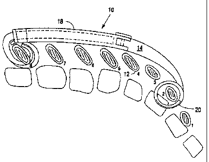
Fig. 6 is a perspective anatomical view of one thoracodorsal expander
implanted on
(one side of a patient's spinal column.
Fig. 7 is an elevational, partially sagittally cross sectional view of the
upper portion of
a thoracodorsal distracter of Applicant's invention. This view depicts the
increased curvature
of the upper portion of the distracter so as to accommodate the more curved
contour of the
more upper thoracic ribs at the distracter's line of attachment thereto.
Fig. 8 is a side elevational view of a segment of a thoracodorsal distracter
as
connected to a rib (shown in cross section) byway of a metallic rib sling.
Fig. 9 is a side elevational view of the auto-lock rib carriage of Applicant's
preferred
embodiment.
Fig. 10 is the auto-lock rib carnage of Fig. 9 with the upper carriage in the
closed
position.
Fig. 11 is an elevational front view of the auto-lock rib carriage of Fig. 9
with the over
carriage in the open position.
Fig. 12 is a elevational front view of the auto-lock rib carnage of Fig. 9
with the over
carriage in the closed position.
DC1: 359153.1
CA 02136189 2003-11-21
Fig. 13A is a front elevational view of the saddle lock for use with the auto-
lock rib
carnage of Fig. 9.
Fig. 13B is a rear elevational view of the saddle lock of Fig. 13A.
Fig. 13C is a side elevational view of the saddle lock of Fig. 13A.
Fig. 14A is a top plan view of the carnage shaft lock for use with the auto-
lock rib
carnage of Fig. 9.
Fig. 14B is a front elevational view of the carriage shaft lock of Fig. 14A.
Fig. 15 is a bottom plan view of a portion of a thoracodorsal distractor
having
Applicant's improved expansion system.
Fig. 16 is a top plan, partial cut away view of the portion of the
thoracodorsal
distractor of Fig. 15.
Fig. 17 is an enlarged portion of Fig. 15 with the distractor shaft removed
for
visibility of the rack portion of Applicant's improved expansion system.
Fig. 18 is a cross-sectional view (perpendicular to the long axis of the
distractor) of a
portion of Applicant's improved expansion system with the geared probe shown
close to
operative position for operation of the system.
Fig. 19 is a side elevational view of the probe used in Applicant's improved
expansion system for the thoracodorsal distractor.
Fig. 20 is an end elevational view of the tip of the probe of Fig. 19 showing
the gear
and pin affixed at the lower end thereof.
Fig. 21 is a cross-sectional view (perpendicular to the long axis of the
distractor) of a
portion of Applicant's improved expansion system.
Fig. 22 is a side elevational view of a portion of Applicant's improved
expansion
system showing operation and position of the ratchet mechanism portion of such
system.
Fig. 23 is a bottom plan view of the ratchet mechanism component of
Applicant's
improved expansion system for his thoracodorsal distractor.
Fig. 24 is an end elevational view of the ratchet mechanism of Fig. 23.
Fig. 25 is an elevational, partially cross-sectional view of the micro access
distraction
lock component of Applicant's improved expansion system for his thoracodorsal
distractor.
Fig. 26 is an exploded, side elevational view of the locking disk and hex
screwdriver
components of the micro access distraction lock component of Applicant's
improved
expansion system for his thoracodorsal distractor.
Fig. 27 is a bottom plan view of the threaded cap disk of the locking disk of
Fig. 26.
_g_
DC1: 359153.1
CA 02136189 2003-11-21
Fig. 28 is a bottom plan view of the threaded cap disk of the locking disk of
Fig. 26.
Refernng to FIG. 1, a first embodiment of the device of Applicant's invention
(hereinafter usually referred to as the "thoracodorsal distractor") is
identified generally by the
reference numeral (10). This embodiment is the simplest one and is designed,
by virtue of its
attachment means (to be identified later) to be attached to upper thoracic and
lower lumbar
natural ribs. Alternative embodiments with different attachment means at the
lower end of the
distractor will be discussed later herein.
The thoracodorsal distractor (10) is designed to be adjusted in length
subsequent to
implantation. The primary purpose of the adjustability being to accommodate
growth of a
child in whom the thoracodorsal distractor (10) is implanted or to allow for
dynamic
treatment scoliosis and other spinal anomalies (to be discussed later). The
adjustability is also
a benefit in using a single sized thoracodorsal distractor (10) for
applications requiring
varying distractor lengths. This permits use of a single sized distractor (10)
in a single patient
in different positions or in different patients with varying physiological
dimensions. Both of
these scenarios have obvious financial benefits to the patients) when compared
with having a
number of custom fabricated prostheses made for very specific, limited
applications.
Referring to FIGS. 1, 2, and 3, the thoracodorsal distractor (10) comprises
three
principal components: a upper distractor sleeve carriage attachment (14), a
distractor
shaft/lower distractor shaft carriage attachment (16), and a distractor sleeve
(18). The
distractor shaft/lower distractor shaft carnage attachment (16) is a single
object of unitary
construction, but for discussion purposes may be divided between the
distractor shaft (16a)
and the lower distractor shaft carriage attachment (16b).
Unless otherwise specified, all components of the thoracodorsal distractor
(10), except
the distractor sleeve ( 18) which is made of Titanium Alloy 64, are
manufactured of
Commercially Pure (CP) Titanium. The use of titanium is dictated by the
strength and
flexibility requirements for the components of the thoracodorsal distractor
(10) in light of the
dimensions of such components. Other materials, such as surgical grade
stainless steel, may
be used in constructing the thoracodorsal distractor (10), but at the expense
of the optimum
balance of benefits derived from titanium. Another benefit arising from the
use of titanium is
derived from the fact that it is not a ferromagnetic metal. As such, titanium
is compatible with
magnetic resonance imaging (M.R.L) scanning, a much preferable diagnostic
procedure,
particularly with patients who would normally be considered as recipients of
Applicant's
thoracodorsal distractor ( 10).
-9-
DC1: 359153.1
CA 02136189 2003-11-21
The upper carnage attachment (14) is provided with a pair of rods (20) and the
lower
carnage attachment (16b) is provided with a similar pair of rods (20). The
rods (20) serve as
the attachment means for anchoring the thoracodorsal distracter ( 10) to
natural ribs ( 12) and
will be discussed in detail hereinafter.
Refernng again to FIGS. 1, 2, 3 and 4, the distracter sleeve (18) may be
described as
an elongate, semi-oval partial conduit with a lengthwise oriented channel (22)
interrupting
the lower surface of the distracter sleeve (18). The presence of the channel
(22) is in response
to manufacturing cost limitations. It should be understood that a suitable
alternative sleeve
which lacks the channel (22) entirely (not shown in the drawings) would be
acceptable for the
purposes stated herein, but would be available, if at all, at a considerably
higher price because
of difficulties in manufacturing such a sleeve. For that reason, the depicted
distracter sleeve
( 18) would be considered a preferred embodiment.
Referring to FIGS. 1, 2, 3 and 5, the distracter shaft (16a) is of solid
construction and
has a lengthwise oriented ridge (not visible in the drawings). The ridge is
designed to
mechanically interface with the channel (22) when the distracter shaft (16a)
is telescopically
received within interior lumen (24) of the distracter sleeve (18) as it is
designed to do. While
the presence of the channel does tend to weaken the distracter sleeve (18) in
resisting axial
rotation relative to the distracter shaft (16a), or vice versa, when a torque
is applied to either,
the restraining action of the ridge's interface with the channel (22)
compensates completely
for any such tendency. Prior to incorporating the ridge into the distracter
shaft (1 6a) design,
experimentation revealed a marked tendency toward such relative rotation
particularly when
the thoracodorsal distracter (10) was extended to near its maximum extent.
The distracter shaft (16a) and the distracter sleeve (18) are formed whereby
they
jointly define a single arc having a constant radius of curvature in a single
plane regardless of
the degree the distracter shaft (16a) is received within the distracter sleeve
(18). The radius of
curvature of the distracter sleeve (18) and distracter shaft (16a) may both be
adjusted in the
manufacturing process according to the expressed preference of the responsible
surgeon, as
dictated by the physiology of the intended recipient.
Refernng principally to Figures 1 and 7, the upper distracter sleeve carriage
attachment (14) projects through the same plane as the distracter sleeve (18)
and distracter
shaft/lower distracter shaft carriage attachment (16) and is also arcuate in
configuration.
However, the upper sleeve carriage attachment (14) has a curvature of smaller
radius than
that of the distracter sleeve (18) and distracter shaftllower distracter shaft
carriage attachment
- 10-
DCI: 359153.1
CA 02136189 2003-11-21
(16) so as to conform to the contour defined by portions of the more upper,
thoracic natural
ribs (12) over which the thoracodorsal distractor (10) extends once implanted
(as in Figure 7).
Both the upper and lower portions of the thoracodorsal distractor (10) are
intended, in
practicing the Applicant's methods for treating and managing scoliosis, to
extend along the
trough or "posterior gutter" collectively defined by the ribs on one side of
and immediately
adjacent to the spine as illustrated in FIG. 6. The lower portion of the
distractor (10) mimicks
a conventional segmental spinal hook system attachable directly to the spine
by hooks (21 S)
(such as a Harrington rod system). Metallic rib slings (217) are shown
connecting
intermediate ribs to the distractors.
By way of example only, Applicant has determined for one patient, a juvenile
(at the
time of this Application, not yet having received a thoracodorsal distractor)
that the
appropriate radius of curvature for the upper distractor sleeve carnage
attachment (14) is
approximately 13.5 cm while that of the distractor shaft/lower distractor
shaft carnage
attachment (16) is approximately 40 cm.
Refernng principally to FIGS. l and 3, the effective length of the
thoracodorsal
distractor (10) is determined by the length of the distractor sleeve (18) and
the degree to
which the distractor shaft (16a) is telescopically received within the
distractor sleeve (18).
The fixed length of the upper distractor sleeve carnage attachment (14) is, of
course, also
partially determinative.
The variable spatial separation of the natural ribs (12) to which the
implanted
thoracodorsal distractor is attached is but one advantage of Applicant's
design. It is important
to note that as the distractor 10 is lengthened (as in the case where the
distractor (10) is
implanted on the concave side of a scoliotic curve wherein it is used to
distract natural ribs
(12) on either side of the curve and to thereby force the spinal column into a
more straight
orientation), its medial portions move posteriorly relative to the patient's
central anatomical
axis. This is a function of the arc in which the lower portions of the
distractor, as formed by
the distractor sleeve (18) and the distractor shaft (16a), extend as they
telescopically expand.
Consequently, when natural ribs are tethered to the distractor (10) (as in
Figure 6), they are
drawn outward so as to more properly align them and to derotate the vertebrae
to which these
ribs (12).are attached. The combination of the distraction of the marginal
attachment ribs (12)
and the derotation of the spine as just described provides a highly effective
treatment
modality for the deviations in all planes associated with scoliosis.
-11-
DCI: 359153.1
CA 02136189 2003-11-21
To secure the relative positions of the distracter shaft (16a) and the
distracter sleeve
(18) once a desired length is attained, the distracter shaft (16a) has a
plurality of evenly
spaced holes (26) passing there-through. The distracter sleeve (18) of one
embodiment has
two holes (28) spaced complementarily to the holes (26) in the distracter
shaft (16a). The
holes (28) in the distracter sleeve (18) are situated on the outer face of the
distracter sleeve
(18). The upper distracter sleeve carriage attachment (14) also has one hole
(30) passing
through its sleeve engaging projection (14a).
The holes (26), (28), and (30) are oriented whereby a linear object may
concurrently
extend through one of the two holes (28) in the distracter sleeve (18) and one
of holes (26) in
the distracter shaft (1 6a) when the distracter shaft (1 6a) is telescopically
received within one
end of the distracter sleeve (18). Likewise, a second linear object may extend
through the
other hole (28) in the distracter sleeve (18) and through hole (30) in the
upper distracter
sleeve carriage attachment (14) when the sleeve projection (14a) is
telescopically received
and properly positioned within the ether end of the distracter sleeve (18).
Refernng principally to FIGS. 1 and 3, once the distracter shaft (1 6a) and
the
distracter sleeve (18) are properly, relatively positioned, they are secured
using a distraction
lock (32). One embodiment of the distraction lock (32) includes a pin (not
separately
identified in the drawings) long enough to extend through either holes (28)
and (26) or
through holes (28) and (30) when in position on the assembled thoracodorsal
distracter (10),
but not long enough to extend beyond the termini of the gripper flanges of the
locks (32). The
tip of the distraction lock's (32) pin as well as the termini of its gripper
flanges are rounded.
The limit on the length of the pin (34) and the just referenced rounding are
in satisfaction of
safety concerns. Sharp edges and slender protrusions are to be avoided in
anticipation of the
distraction lock (32) possibly becoming dislodged after implantation and have
been so
avoided in Applicant's preferred embodiment of the distraction lock.
Referring principally to FIGS. 1 and 3 the distracter sleeve (18) has two
pairs of
recesses (29) with which the distraction locks (32) are designed to mate. Each
recess (29) is
formed having a first zone with a depth such that the gripper flanges (36) of
a distraction lock
(32) must yield slightly to pass thereover, this zone being nearer the top of
the distracter
sleeve (18). A second zone (31), slightly deeper into the distracter sleeve
(18), is separated by
a palpable line of demarcation visible in FIGS. 1 and 3 and lies closer to the
bottom of the
distracter sleeve (18). The gripper flanges (36) "snap" into the lower, deeper
portion of their
respective recesses (29) when a distraction lock (32) is installed. In this
manner, the
-12-
DC1: 359153.1
CA 02136189 2003-11-21
distraction lock (32) is securely held in place until or unless pried from the
distracter sleeve
(18). An alternative embodiment of the distracter sleeve (18) (not shown in
the drawings)
incorporates multiple pairs of recesses (29) and associated holes (28) near
one end of the
distracter sleeve (18). Such a distracter sleeve (18) may be shortened using a
hack saw at the
S time of surgery to shorten the starting, most retracted over all length for
the thoracodorsal
distracter (10) leaving a fully functional distracter sleeve end having the
necessary pair of
recesses (29) and hole (28). When shortening this embodiment of the distracter
sleeve (18),
the distracter sleeve (18) is simply cut at a point between adjacent pairs of
recesses (29) and
the cut end is then smoothed using a file. Such an alternative embodiment of
the distracter
sleeve (18) permits its use in situations which otherwise would require the
manufacture of a
shorter distracter sleeve (18). Wider applicability for any one component of
Applicant's
invention has obvious financial benefits to recipient patients.
The holes (26) in distracter shaft (16a) in the preferred embodiment for use
in very
young children have been spaced in lOmm intervals in anticipation of the
likely growth
intervals which will indicate an adjustment of the thoracodorsal distracter
(10). Such spacing
is in recognition of the fact that only slight misalignment of the spinal
column can result in
discomfort and possible spinal cord injury.
Referring principally to FIGS. 2 and 7, both the upper distracter sleeve
carriage
attachment (14) and the distracter shaft carriage attachment (16b) (of the
simplest
embodiment of the thoracodorsal distracter (10)) include two rods (20) at
their respective
ends. The rods (20) are round in cross section. The rods (20) have a cross
sectional diameter
of 2mm in the preferred embodiment. The rods' (20) round cross sectional shape
was chosen
as a means for minimizing the biological trauma to the periosteum of the ribs
(12) and to the
inferior surfaces of the ribs (12) where the rods (20) have their primary
contact therewith (to
be discussed in more detail hereinafter).
The specific 2mm diameter of the rods (20) was chosen after numerous
alternative
specifications were tested. A 2mm diameter of CP Titanium has proven to
provide the
optimum balance between the flexibility necessary for safe manipulation during
implantation
and strength necessary for post-implantation stability. No other material
tested in a 2mm rod
configuration and no other dimension in CP Titanium provided the preferred
characteristics
for the rods (20).
The rods (20) of the preferred embodiment are 76mm in length. This length has
been
shown through experimentation to provide a quite acceptable degree of surplus
length to
-13-
DCI: 359153.1
CA 02136189 2003-11-21
facilitate the needed manipulation during implantation both to circumvent the
natural ribs
(12) at the basic level, as well as to adjust the orientation and position of
the loops formed
from the rods (20) in determining the over-all orientation of the
thoracodorsal distractor (10)
within the patient. The indicated length does not, however, introduce
excessive length which
would impede manoeuvring during implantation and require excessive bending to
avoid
surrounding tissues.
Refernng principally to FIG. 7, the rods (20) are during the implantation
procedure
manipulated by the surgeon to circumvent the appropriate natural rib (12). The
path of the
rods (20) about the natural rib (12) is essentially circular when properly
Implanted, even
though the rib would be better described as oblong. This is an important
aspect of practicing
Applicant's invention for several independently significant reasons. The
circular
circumvention permits the carnage attachments (14) and (16b) to pivot relative
to the natural
ribs (12). This is, important, in part, because the carnage attachments (14)
and (16b) change
orientation relative to the ribs (12) to which they are attached as the length
of the
thoracodorsal distractor (10) is changed subsequent to implantation.
The ability of the carnage attachments (14) and (16b) to pivot is further
important in
allowing the thoracodorsal distractor (10) to partially accommodate traumatic
force which
may occur in falls, etc. while not transfernng the force to the natural ribs
(12) in a manner
which would likely fracture the natural ribs (12) or damage the spine to which
the distractor
(10) is so closely attached. If the carnage attachments (14) and (16b) were
rigidly attached to
natural ribs (12), the carriage attachments (14) and (16b) would apply a
possibly damaging
torque to the natural ribs ( 12) in response to a traumatic force to the
distractor shaft ( 16a)
and/or distractor sleeve (18). This is substantially avoided by the circular
path of
circumvention suggested herein. Also, the relatively loose circumvention of
the natural ribs
(12) tends to "cage" the rib, not clamp it, obviating the danger of rib
ischemia at the site of
contact between the rods (20) and the natural rib (12) surface. Still further,
the gentle
movement permitted by the preferred mode of attachment for the thoracodorsal
distractor
(10) and brought about by normal movement of the recipient has the tendency to
promote
work hypertrophy thereby actually strengthening the natural rib (12).
When the thoracodorsal distractor (10) is properly implanted and adjusted, the
principal contact of the rods (20) with the natural ribs (12) is to inner
surface areas of the
natural ribs (12) relative to the intervening chest wall defect. In this
manner, the rods (20)
- 14-
DC1: 359153.1
CA 02136189 2003-11-21
"cradle" the natural ribs (12) at a point of minimum contact as opposed to
deleteriously
compressing them.
The rods (20) number two for each of the carnage attachments (14) and (16b) in
satisfaction of some of Applicant's material objectives in designing the
preferred
embodiment. Most notably, dual attachment sites for the carnage attachments
(14) and (16b),
as opposed to a singular attachment site, provide substantial rotational
stability for the
thoracodorsal distractor ( 10). By way of comparison, a single site of
attachment will do little
to stabilize the thoracodorsal distractor (10) against even minor deflective
forces while a dual
attachment quite ably resists such force. Also, the cumulative mass of
titanium needed for
strength of the attachment to the natural ribs (12) can be divided between the
two rods (20) as
opposed to being embodied in a single, larger rod. Such a single rod would be
too stiff to
safely manipulate during implantation if it incorporated the same quantum of
titanium as is
divided between the two rods (20) of each carriage attachment (14) and (16b)
of the preferred
embodiment.
The use of three or more rods (20) is not recommended because of the
associated
consumption of surface space on the natural ribs (12) and the minimal
additional stability
which would be achieved. Because a plurality of thoracodorsal distractors (10)
will be
required in most situations requiring any use of the thoracodorsal distractor
(10),
conservation of natural rib (12) surface space is desired.
A sample surgical procedure involved in implantation of the thoracodorsal
distractor
is outlined as follows:
Three 4 cm longitudinal skin incisions are required. The first incision is
made at the
base of the thoracic spine. It is carned down to the paraspinal muscles
overlying the posterior
spinous processes of the thoracic spine. The soft tissues and the osseous
elements of the spine
are not violated in order to minimize the risk of accidental spine fusion.
Dissection then
continues laterally over the top of the paraspinous muscles to avoid
denervation of the
muscle. This carries the incision deep to the medial rib at its intersection
with the transverse
process.
The selected point of rib attachment is chosen and a periosteum incision made
over
the rib. The retractors are inserted to elevate the periosteum off the rib and
this protects both
the inferior neurovascular bundle of the rib and also the underlying lung.
Pneumothorax is the
only serious complication of the operative procedure and the risk is minimal
with
subperiosteal direction which orthopedists are very familiar with. Once the
rib site is
-15-
DCI: 359153.1
CA 02136189 2003-11-21
prepared, then a second and third site is prepared both at the central portion
of the thoracic
spine and at the upper portion of the spine. The surgical sites involve
reflection of the
trapezius muscles laterally. From the central and inferior operative sites,
and in addition, the
levator scapuli and rhomboid muscles are reflected laterally at the superior
prosthesis
attachment site. Next, a malleable rod of similar dimensions of the prosthesis
is threaded
carefully from the central operative exposure site lowerly. until visible in
the lower site. A
similar rod is then threaded through the central site upperly. A thick plastic
tube is then
anchored to the first malleable rod at the lower site and then threaded up to
the central site.
Next, the plastic tube is then anchored to the upper malleable rod and
threaded out to the
upper operative site. Next, the prosthetic sleeve and shaft are attached to
the plastic at the
inferior site and manipulated through both twisting and gentle pushing up the
paraspinal
gutter until it is in the proper position for implantation. The plastic tube
is pulled during this
manoeuvring and it guides the prosthesis through the hole made by the
malleable rods and
prevents the upper end of the prosthesis from accidental plunging into the
thorax and causing
either cardiac or pulmonary damage (one known complication of subcutaneous
threading of a
straight Harnngton or Moe rod in this fashion is plunging of the sharp
straight end of the rod
into the chest as it attempts to pass over the apex of the thorax of the
central thoracic spine).
Once in position, the rib carriages are engaged to the upper and lower ribs
exposed by prior
subperiosteal direction. If a titanium sling loop is necessary at the central
incision, then it is
threaded around a prepared rib and loosely around the prosthetic sleeve.
Referring to FIGS. 9, 10, 11 and 12, an alternative (and preferred) upper
fixation
device (the auto-lock rib carnage) is identified generally by the reference
numeral (110).
Auto-lock rib carriage (110) includes an approximately 3/4 circle under
carnage ring (112)
with a slidably journaled over carriage ring (114) movably engaged therewith.
As is clear
comparing FIGS. 9 and 10, simply rotating the over- carriage ring (114)
relative to the under
carriage ring (112) forms (or alternatively opens) a fully enclosed circle.
Use of the auto-lock rib carriage (110) greatly simplifies attachment of a
thoracodorsal distractor as compared with use of rods (20) as described above
with reference
to distractor (10). One simply positions the auto-lock rib carnage (110) in
proper position and
orientation relative to the designated upper attachment rib (12), moves the
over carnage ring
(114) so as to close the circle about the rib (12), and locks the over
carriage ring (114) in
place.
-16-
DCI: 359153.1
CA 02136189 2003-11-21
Referring principally to FIGS. 9, 10, 13A, 13B and 13C, over carnage ring
(114) has
a lip ( 118) which is sized for reception into a slot ( 120) formed in the
base ( 122) of the auto
lock rib carriage (110). A saddle lock (124) with a locking cam (126) is
designed to lock into
position on the base (122) at an interlock site whereby the locking cam (126)
securely holds
the over carnage, ring (114) in its closed position.
Referring principally to FIGS. 9, 10, 11 and 12. the under carriage (112)
includes a
carnage shaft (130) a terminal portion of which is formed into a spline (132).
In an unshown
embodiment of a thoracodorsal distractor which employs the auto-lock rib
carriage (110), the
upper end of the distractor sleeve (18) is formed into a socket which is
suitably contoured to
effectively mate with the spline portion (132) of the carnage shaft (130).
This arrangement,
among other benefits, allows the user to orient the auto-lock rib carriage
(110) in any of
numerous positions relative to the distractor sleeve (18). This is a
particularly important
benefit, in light of the potentially unpredictable course and orientation of
ribs (12) in a
scoliosis patient to which a user may want to attach the distractor at the
upper end.
Refernng principally to FIGS. 9, 10, 14A and 14B, the carnage shaft (130) has
a shaft
lip (134) which, in cooperation, with a carriage shaft lock (136), serves to
securely lock the
auto-lock rib carnage (110) and the suitably modified distractor sleeve (not
separately shown
in the drawings) together. The carnage shaft lock (136) having, as it does, a
shaft lock pin
(138), is designed to snap into position relative to a recipient hole,
analogous to hole (28) as
described above (not shown in the drawings) on the distractor sleeve (18) in
the same manner
as the distraction locks (32) as described above. The carriage shaft lock
(136) also exhibits a
shaft lip clamp (140) which is sized and shaped to juxtapose the carnage shaft
(130) on the
side of the shaft lip (134) opposite the spline (118). The recipient hole in
distractor sleeve
(18) is positioned relative to the upper terminus of the distractor sleeve
(18), so that the shaft
lip clamp (140) is positioned relative to the shaft lock pin (138) such that,
when the carnage
shaft (130) is fully received within the socket of the distractor sleeve (18),
and the carnage
shaft lock (136) is pressed into position, the interaction of the shaft lip
clamp (140) and the
shaft lip (134) prevents separation of the auto-lock -rib carnage (110) from
the distractor
sleeve ( 18).
Referring principally to FIGS. 9 and 10, to prevent lateral shifting of the
autolock rib
carnage (110) relative to the natural rib (12) to which is attached, a rib
spike (142) is
positioned on the base (122) of the auto-lock rib carriage (110) projecting
into the circle
defined by the over carriage ring (114) and the under carriage ring (112).
While this will
-17-
DCI: 359153.1
CA 02136189 2003-11-21
retard some movement of a thoracodorsal distractor relative to a natural rib
(12) to which it is
attached, and will, therefore, reduce some of the potential energy dissipation
as discussed
above, the ability of the natural rib (12) to oscillate within the confines of
the circle defined
by the over carriage ring (114) and the under carnage ring (112) in response
to everyday
forces will dissipate energy and promote work hypertrophy to a very beneficial
degree as
compared with any imaginable rigidly fixed systems.
Referring principally to FIGS. 15, 16, 17, 18, 19 and 21, relevant portions of
a
preferred embodiment of a thoracodorsal distractor (310) as relates to the
means for
expanding and contracting the over-all length of the device is shown. The
principle object
served by this aspect of the system is to allow for post-implantation length
adjustment by way
of very simple, out-patient surgery.
The expansion/retraction system provided in FIGS. 15, 16, 17, 18, 19 and 21 is
based,
in part, upon a rack and pinion-like system. A portion of the internal margin
of the distractor
sleeve (312) is formed into a gear track or rack (314). The rack (314) is
positioned superior to
the channel through which the distractor shaft(318) extends and inferior to
the top face (319)
of the distractor sleeve (312) (partially removed in FIG. 16) for visibility.
A screwdriver-like probe (316) (see FIG. 19) exhibits a gear (320) at its
lower end
which gear (320) is sized and configured to mate with the teeth of rack (314).
Extending
axially from exposed face of the gear (320) is a pin (322) which is sized and
shaped for
insertion into one of the distraction holes (324) in the distractor shaft
(318).
The top face (319) of the distractor sleeve (312) exhibits a three lobed
orifice (326),
each lobe of which is sized for receiving gear (320) therethrough for
engagement with the
rack (314). The margins of each lobe of orifice (326) is also threaded for
threadingly mating
with a locking system (to be described later). The lobes of the orifice (326)
are configured
whereby the gear (320) may be engaged or disengaged from the rack (314) of the
distractor
sleeve (312) and from the distractor shaft (318) at 0.5 cm intervals.
Operation of the expansion/retraction system of FIGS. 1 S, 16, 17, 18, 19 and
21
merely involves inserting the gear (320) of the probe (316) through the
medialmost lobe of
orifice (326), axially rotating the probe (316) in a counter-clockwise
direction (from the
perspective of the user), and removing the probe (316) from either of the two
adjacent lobes
of orifice (326) (depending on the extent of expansion desired). Of course, if
more than 1.5.
cm of expansion is desired, the process can be repeated.
-18-
DC1: 359153.1
CA 02136189 2003-11-21
Refernng to FIGS. 22, 23 and 24, Applicant provides a ratchet mechanism (330)
for
affixation to the distractor sleeve (312). The ratchet mechanism (330)
includes dual leaves
(332) each of which exhibits a locking cam (334) sized and shaped for
extending into one of
the distraction holes (324) in the distractor shaft (318) (as allowed through
a suitably sized
and shaped portal in the top face (319) of the distractor sleeve (312).
Referring principally to FIG. 22, the locking cams (334) are each contoured
such that,
when the ratchet mechanism (330) is oriented as shown in FIG. 22, they allow
expansion, but
not contraction of the distractor (310). In other words, each locking cam
(334) exhibits a
flattened face which is oriented toward the upper end of the distractor (310),
but an obliquely
oriented face which is oriented toward the upper end of the distractor (310).
The operation
and effect of the ratchet mechanism (330) is self evident from the figures.
Referring principally to FIG. 1 S, as with the distraction locks (32) as
described above,
the ratchet. mechanism (330) is configured to snap onto the under surface of
the prosthesis
into indentations (338) formed on the outer surface of the distractor sleeve
(312). This design
permits a user during initial implantation to freely move the distractor (310)
and only after
reaching the appropriate minimal length thereof, affixing the ratchet
mechanism (330) to
prevent inadvertent contraction.
Refernng principally to FIGS. 25, 26, 27 and 28, Applicant's design further
includes a
locking system for use with the just-described expansion/retraction system.
This system
centers on a locking disk (340) which includes a locking disk pin (342), a
free gear (344), a
lock washer (346), and a threaded cap disk (348). The threaded cap disk (348)
has a
hexagonal recess (350) in its exterior face for mating with a complimentarily
shaped and
sized tip (362) of a hex screwdriver (352). From the base of the hexagonal
recess (350) is a
threaded column (354) which is sized for threadingly mating with a threaded
rod (356) which
extends axially through the center of the hex screwdriver (352). The locking
disk pin (342) is,
in the preferred embodiment, an integral part of the threaded cap disk (348)
and includes an
annular gear-retaining bead (360) for maintaining the free gear (344) thereon
with the lock
washer (346) intervening the free gear (344)-and the interior face of the
threaded cap disk
(348). The locking disk pin (342) is sized and shaped for extending into one
of the distraction
holes (324) in the distractor shaft (318) and is tapered so as to relieve
tension from the ratchet
mechanism (330) between adjustments of the distractor (310).
Once the distractor (310) is adjusted for length as desired as described
above, a user
of Applicant's system secures the threaded cap disk (348) to the hex
screwdriver (352) by use
- 19-
DC1: 359153.1
CA 02136189 2003-11-21
of the threaded rod (356). The user then directs the locking disk (348) toward
the medial most
lobe of the orifice (326) on the distractor sleeve (312) and appropriately
rotates the hex
screwdriver (352) until the threaded cap disk (348) is fully seated in the
orifice (326)
whereby the locking disk pin (342) extends into the underlying hole (324) in
the distractor
shaft (318), the free gear (344) is mated with the rack (314) of the
distractor sleeve (312) and
lock washer (346) is compressed to the point were the threaded disk cap (348)
will not
accidentally become disengaged from the distractor sleeve (312). The user then
disengages
the hex screwdriver. (352) from the threaded cap disk (348) and doses the
puncture wound
used to access the distractor (310).
-20-
DC1: 359153.1