Language selection

Search

Patent 2136267 Summary

Third-party information liability

Some of the information on this Web page has been provided by external sources. The Government of Canada is not responsible for the accuracy, reliability or currency of the information supplied by external sources. Users wishing to rely upon this information should consult directly with the source of the information. Content provided by external sources is not subject to official languages, privacy and accessibility requirements.

Claims and Abstract availability

Any discrepancies in the text and image of the Claims and Abstract are due to differing posting times. Text of the Claims and Abstract are posted:

  • At the time the application is open to public inspection;
  • At the time of issue of the patent (grant).
(12) Patent Application: (11) CA 2136267
(54) English Title: RADIO SPEAKER SHORT CIRCUIT DETECTION SYSTEM
(54) French Title: SYSTEME DE DETECTION DE COURTS-CIRCUITS DANS LES HAUT-PARLEURS D'APPAREIL RADIO
Status: Deemed Abandoned and Beyond the Period of Reinstatement - Pending Response to Notice of Disregarded Communication
Bibliographic Data
(51) International Patent Classification (IPC):
  • G01R 31/00 (2006.01)
  • G01R 31/28 (2006.01)
(72) Inventors :
  • PERSON, ANDREW P. (United States of America)
  • MUCCIOLI, JAMES P. (United States of America)
(73) Owners :
  • CHRYSLER CORPORATION
(71) Applicants :
  • CHRYSLER CORPORATION (United States of America)
(74) Agent: MARKS & CLERK
(74) Associate agent:
(45) Issued:
(22) Filed Date: 1994-11-21
(41) Open to Public Inspection: 1995-05-23
Availability of licence: N/A
Dedicated to the Public: N/A
(25) Language of filing: English

Patent Cooperation Treaty (PCT): No

(30) Application Priority Data:
Application No. Country/Territory Date
08/155,720 (United States of America) 1993-11-22

Abstracts

English Abstract


A radio speaker short circuit detection system for a
vehicle visually indicates a speaker short circuit failure. A
microprocessor receives a short circuit failure signal from a
short circuit detection circuit. Short circuit failure data can
be stored for future diagnostic retrieval.


Claims

Note: Claims are shown in the official language in which they were submitted.

-7-
THE EMBODIMENTS OF THE INVENTION IN WHICH AN EXCLUSIVE
PROPERTY OR PRIVILEGE IS CLAIMED ARE DEFINED AS FOLLOWS:
1. A short circuit detection system for indicating
speaker short circuit failure of a radio system in a vehicle,
comprising:
short circuit detection means for detecting short
circuit failure and for generating a short circuit signal in
response to said detected short circuit failure;
microprocessor means coupled to said short circuit
detection means for receiving said short circuit signal and
thereafter generating an error signal; and
first indication means coupled to said
microprocessor means for receiving said error signal and
indicating short circuit failure in response thereto.
2. A short circuit detection system as recited in claim
1, further comprising a multiplex bus coupled to said
microprocessor means, a storage means coupled to said
microprocessor means for storing said short circuit signal for
retrieval at a later time, and a receiving means for receiving
said stored short circuit signal when said receiving means is
coupled to said multiplex bus.
3. A short circuit detection system as recited in claim
2, wherein said receiving means has second indication means.

-8-
4. A method for indicating speaker short circuit
failure of a radio system in a vehicle, comprising the steps of:
A) detecting speaker short circuit failure;
B) sending a short circuit failure signal in response
to said detecting step;
C) generating an error signal in response to said short
circuit failure signal and sending said error signal to an
indication means; and
D) displaying an error message in response to said
short circuit failure signal.
5. A method as recited in claim 10, further comprising
the steps of:
E) storing said short circuit failure signal into a
storage means; and
F) retrieving said stored short circuit failure signal.

Description

Note: Descriptions are shown in the official language in which they were submitted.


~- 213~267 9~ ~20
aADIO SP~ARXB SUOKT CIBCUIT D~T~CTIO~ S~ST~
BAC~GBOu~ OF T~E l~hnllO~
Field of the Invention
The present invention relates to automotive audio short
circuit detection and protection. More particularly, the
invention relates to a short circuit detection system that
provides visual indication of short circuit failure and stores
the failure information for future retrieval.
Back~round Art
Automotive audio power amplifier integrated circuits (ICs)
have implemented short circuit protection by many methods.
These protection methods result in "NO AUDIO" from the radio.
Consequently, the customer or the dealer doesn't know if the
radio i8 defective, the wiring harness is open or shorted, or
the loudspeaker is open, shorted, or blown. Since of the
components of a sound system the radio is the easiest to
replace, the dealer typically starts to troubleshoot the sound
system by replacing the radio, resulting in many radio warranty
claims for removing or replacing a good radio for which no
trouble is found.

2~ 3~267
64,164-014
-2-
The present invention will eliminate these "NO TROUBLE
FOUND" radio warranty claims by indicating detected speaker
error with a displaying of a "SP Err" indication on the radio
display when short circuit is detected. The short circuit
failure information is stored in EEPROM (electronically erasable
programmable read only memory). The customer receives a visual
indication that the loss of audio is not a radio failure but due
to harness or speaker short circuits.
SUMMARY OF T~L INVE~TIO~
The present invention provides visual indication of
speaker short circuit failure by means of messages sent from the
vehicle's microprocessor to an indication means.
Thus, according to one aspect of the present invention, a
circuit is described for visually indicating speaker short
circuit failure in an automotive vehicle.
According to another aspect of the present invention, a
circuit is described that provides future retrieval of stored
speaker short circuit failure data in a vehicle with a multiplex
bus system.

2 ~ 7
64,164-014
According to yet another aspect of the present invention,
a method for visually indicating speaker short circuit failure
in an automotlve vehicle, comprising the steps of detecting
short circuit failure, sending a first short circuit failure
signal to a microprocessor, and sending a second failure signal
to a display screen.
BBIEF DESC~IPTION OF T~E DBAWI~6S
Other ob~ects, features and advantages of the present
invention will become more fully apparent from the following
detailed description of the preferred embodiment, the appended
claims and in the accompanying drawings in which:
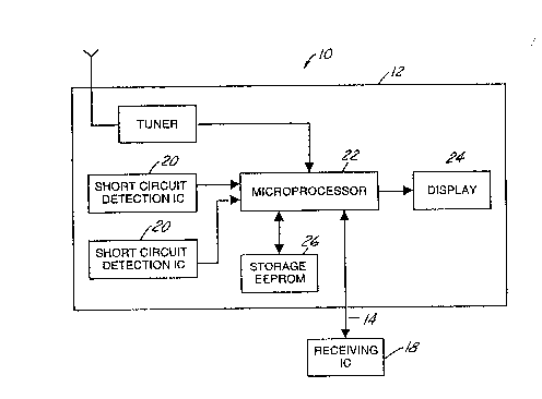
Figure 1 i9 a block diagram of the short circuit detection
system made in accordance w$th the teachings of the preferred
embodiment of this invention.
Figure 2 is a flowchart illustrating the general sequence
of steps associated with the operation of the system shown in
Figure 1.

21~57
64,164-014
PETAIL~D DLSC~IPTIO~ OF IE~ ~K~K~ MBODIMERIS
Referring now to the drawings, wherein like reference
numerals are used to identify identical components in various
views, Figure 1 depicts a radio speaker short circult detection
system 10 made in accordance with the teachings of the preferred
embodiment of this invention. As shown, circuit detection
system 10 include~ an automotive radio 12, coupled by a vehicle
multiplex bus 14 to a receiving means 18.
The automotive radio 12 includes a short circuit detectlon
circuit 20 for each left audio channel and right audio channel.
A detection circuit 20 is able to detect a short circuit
condition on the output of either the right audio ch~nel or the
left audio channel. The detection circuit 20 can be one of a
number of commercially available circults. When the detection
circuit 20 detects a short circuit in a speaker it sends a short
circuit signal to a microprocessor 22. The microprocessor 22
receives the short circuit signal and thereafter generates a
corresponding error signal. A display 24 receives the error
signal and responds by visually indicating a short circuit
failure to the user.
The display 24 can be a vacuum-flourescent display or a
liquid crystal display. Accordingly, the display 24 visually

2~ ~?~7
64,164-014
notifies the user that the "NO AUDIO" problem is not due to a
failure of the radio, but of the speaker or wiring harness.
This information can be continuously displayed to the user.
Alternatively, it can be displayed for a predetermined period of
time and then stopped and again displayed upon ignition reset.
In addition, a storage circuit 26 is provided to store the
short circuit signal sent to microprocessor 24 for retrieval at
a later time. The storage circuit 26 can be in the fonm of an
electrically erasable programmable read only memory (EEPROM)
IC. Retrieval of the stored short circuit signal can be
accomplished by coupling a receiving tool 18 to multiplex bus
14. The receiving tool 18 can be an interface tool that allows
a user to access multiplex bus 14 and send predetermined
formatted messages to the storage circuit 26 via the
microprocessor 24 which seeks stored short circuit signal data.
Referring now to flowchart 42 of Figure 2, there is shown
a general sequence of steps associated with the use of the radio
speaker short circuit detection system 10. An initial step 44
involves determining if there is an audio short circuit
failure. If there is no short circuit failure, step 46
illustrates that an audio signal i8 sent to a loudspeaker and
emits audio sound.

64,164-014 -6- ~ 2 6 7
If there i9 a short clrcuit failure, step 44 is followed
by step 48 in which short circuit detection circuit 20 sends the
appropriate signal to the microprocessor 22. The microprocessor
22 then sends an error message to the display 24 as illustrated
by step 50. In addition, the microprocessor 22 stores this
short circuit failure information into the storage circuit 26 as
shown in step 52. The stored short circuit failure data i8
retrieved by a receiving tool 18, as shown in step 54.
While the present invention has been disclosed with the
preferred embodiment thereof, it should be understood that there
may be other embodiments which fall within the spirit and scope
of the invention and that the invention is susceptible to
modification, variation and change without departing from the
proper scope or fair meaning of the following claims.

Representative Drawing
A single figure which represents the drawing illustrating the invention.
Administrative Status

2024-08-01:As part of the Next Generation Patents (NGP) transition, the Canadian Patents Database (CPD) now contains a more detailed Event History, which replicates the Event Log of our new back-office solution.

Please note that "Inactive:" events refers to events no longer in use in our new back-office solution.

For a clearer understanding of the status of the application/patent presented on this page, the site Disclaimer , as well as the definitions for Patent , Event History , Maintenance Fee  and Payment History  should be consulted.

Event History

Description Date
Inactive: IPC expired 2020-01-01
Inactive: IPC from MCD 2006-03-11
Application Not Reinstated by Deadline 2002-11-21
Time Limit for Reversal Expired 2002-11-21
Inactive: Abandon-RFE+Late fee unpaid-Correspondence sent 2001-11-21
Deemed Abandoned - Failure to Respond to Maintenance Fee Notice 2001-11-21
Application Published (Open to Public Inspection) 1995-05-23

Abandonment History

Abandonment Date Reason Reinstatement Date
2001-11-21

Maintenance Fee

The last payment was received on 2000-11-02

Note : If the full payment has not been received on or before the date indicated, a further fee may be required which may be one of the following

  • the reinstatement fee;
  • the late payment fee; or
  • additional fee to reverse deemed expiry.

Patent fees are adjusted on the 1st of January every year. The amounts above are the current amounts if received by December 31 of the current year.
Please refer to the CIPO Patent Fees web page to see all current fee amounts.

Fee History

Fee Type Anniversary Year Due Date Paid Date
MF (application, 3rd anniv.) - standard 03 1997-11-21 1997-11-04
MF (application, 4th anniv.) - standard 04 1998-11-23 1998-11-04
MF (application, 5th anniv.) - standard 05 1999-11-22 1999-11-05
MF (application, 6th anniv.) - standard 06 2000-11-21 2000-11-02
Owners on Record

Note: Records showing the ownership history in alphabetical order.

Current Owners on Record
CHRYSLER CORPORATION
Past Owners on Record
ANDREW P. PERSON
JAMES P. MUCCIOLI
Past Owners that do not appear in the "Owners on Record" listing will appear in other documentation within the application.
Documents

To view selected files, please enter reCAPTCHA code :


To view images, click a link in the Document Description column (Temporarily unavailable). To download the documents, select one or more checkboxes in the first column and then click the "Download Selected in PDF format (Zip Archive)" or the "Download Selected as Single PDF" button.

List of published and non-published patent-specific documents on the CPD .

If you have any difficulty accessing content, you can call the Client Service Centre at 1-866-997-1936 or send them an e-mail at CIPO Client Service Centre.

({010=All Documents, 020=As Filed, 030=As Open to Public Inspection, 040=At Issuance, 050=Examination, 060=Incoming Correspondence, 070=Miscellaneous, 080=Outgoing Correspondence, 090=Payment})


Document
Description 
Date
(yyyy-mm-dd) 
Number of pages   Size of Image (KB) 
Representative drawing 1998-06-02 1 9
Abstract 1995-05-22 1 8
Description 1995-05-22 6 145
Drawings 1995-05-22 1 23
Claims 1995-05-22 2 44
Reminder - Request for Examination 2001-07-23 1 118
Courtesy - Abandonment Letter (Maintenance Fee) 2001-12-18 1 183
Courtesy - Abandonment Letter (Request for Examination) 2002-01-01 1 172
Fees 1996-10-17 1 54
Courtesy - Office Letter 1995-01-16 2 56