Language selection

Search

Patent 2136652 Summary

Third-party information liability

Some of the information on this Web page has been provided by external sources. The Government of Canada is not responsible for the accuracy, reliability or currency of the information supplied by external sources. Users wishing to rely upon this information should consult directly with the source of the information. Content provided by external sources is not subject to official languages, privacy and accessibility requirements.

Claims and Abstract availability

Any discrepancies in the text and image of the Claims and Abstract are due to differing posting times. Text of the Claims and Abstract are posted:

  • At the time the application is open to public inspection;
  • At the time of issue of the patent (grant).
(12) Patent: (11) CA 2136652
(54) English Title: FIXATION PIN FOR SMALL-BONE FRAGMENTS
(54) French Title: EPINGLE DE FIXATION POUR LES FRAGMENTS DE PETITS OS
Status: Term Expired - Post Grant Beyond Limit
Bibliographic Data
(51) International Patent Classification (IPC):
  • A61B 17/58 (2006.01)
  • A61B 17/86 (2006.01)
(72) Inventors :
  • PENNIG, DIETMAR (Germany)
(73) Owners :
  • DIETMAR PENNIG
(71) Applicants :
(74) Agent: NORTON ROSE FULBRIGHT CANADA LLP/S.E.N.C.R.L., S.R.L.
(74) Associate agent:
(45) Issued: 2000-08-22
(86) PCT Filing Date: 1994-03-19
(87) Open to Public Inspection: 1994-09-29
Examination requested: 1995-02-13
Availability of licence: N/A
Dedicated to the Public: N/A
(25) Language of filing: English

Patent Cooperation Treaty (PCT): Yes
(86) PCT Filing Number: PCT/DE1994/000323
(87) International Publication Number: WO 1994021184
(85) National Entry: 1994-11-24

(30) Application Priority Data:
Application No. Country/Territory Date
P 43 09 707.3 (Germany) 1993-03-25
P 44 06 374.1 (Germany) 1994-02-26

Abstracts

English Abstract


The invention relates to a fixation pin for fixing small
bone fragments to larger bone fragments in osteosynthesis
procedures, the fixation pin consisting of a smooth-walled
shank part and an adjoining threaded part, and the transition
between shank part and threaded part being of conical
development; furthermore, a support disk can be connected to
the fixation pin, the conical step of the fixation pin being
inserted into a correspondingly developed recess in the
support disk and the support disk being developed slightly
concave.


Claims

Note: Claims are shown in the official language in which they were submitted.

THE EMBODIMENTS OF THE INVENTION IN WHICH AN EXCLUSIVE
PROPERTY OR PRIVILEGE IS CLAIMED ARE DEFINED AS FOLLOWS:
1. In combination, a fixation pin for fastening a small
broken bone fragment to a main remaining part of the same
bone, said fixation pin comprising a smooth-walled shank
portion, said pin having a threaded portion of reduced
diameter connected to said shank portion via a transitional
formation, said threaded portion having a sharp distal end
that is self-tapping in bone tissue, and a support disk having
a bore sized for free reception of said threaded portion and
for seating at said transitional formation, said support disk
having an outer diameter greater than the diameter of said
shank portion, and said support disk having a distal face for
relatively large-area contact with a bone fragment when the
distal end of said threaded portion is otherwise fully engaged
to said main bone part via said bone fragment.
2. The combination of claim 1 wherein the threaded
portion of the pin has a fine-pitch thread.
3. The combination of claim 1 or claim 2 wherein at
least the shank portion of the pin is of a material which
permits cutting to length of the pin by cutting pliers.
4. The combination of any one of claims 1 to 3 wherein
the outside diameter of the threaded portion is between 70%
and 80% of the outside diameter of the shank portion.
-7-

5. The combination of any one of claims 1 to 4 wherein
said transitional formation is conically shaped, and wherein
said support disk has a bore that is shaped for engagement by
said transitional formation.
6. The combination of any one of claims 1 to 5 wherein
said support disk is arched concavely in the direction of said
threaded portion of the pin.
7. The combination of any one of claims 1 to 6 wherein
said support disk has rounded outer edges.
8. The combination of any one of claims 1 to 4 wherein
said support disk includes an internal screwthread that is
sized for engagement with said threaded portion of the pin.
-8-

Description

Note: Descriptions are shown in the official language in which they were submitted.


~I366~~
TRANSLATION
from:
FIXATION PIN
The present invention relates to a fixation pin for
osteosynthesis procedures.
In osteosynthesis it is generally known to fix bone
fragments by screws or nails. In the case of small bone
splinters, however, the screws or nails available in the
prior art are much too large to fix these small splinter
particles on the main bone without damage. The fixing of
these bone fragments by means of simple pins and nails is
problematical since the bone particle can slide on the outer
wall of the pin or nail since it is not held by an abutment.
Fixation pins are known from European Patent 314 021 A2
or, for instance, from Federal Republic of Germany 32 44 819
A1, but their object is to fasten the fixator externally on
the bone fragments. In these known fixation pins, the
transition from the threaded part to the shank part is
developed as a linear step and the fixing of the bone
fragments to one another is effected not by the fixation pin
but by an external fixator which is held in place via the
fixation pin.
If a small fixation pin for the fixing of small bone
fragments would also be provided with a linear step, then
upon the screwing in of the fixation pin, this step would
first come into contact with the bone fragment at a
LAWYERS' AND MERCHANTS' TRANSLATION BUREAU INC.
Legal, Financial, Scientific, Technical and Patent Translations
Tel: (212) 344-2930/2931 11 BROADWAY, NEW YORK, NY 10004 Fax: (212) 422-6877
Consultant Founded in 1903 by
WM. BERTSCHE, J.D., CH.E., A.C.S. CARL V. BERTSCHE

21 36652
circumferential place and thereby shift the bone fragment due
to the rubbing produced.
In contrast to this, the object of the invention is
to provide a fixation pin for bone fragments which, despite
its smallness, effects a dependable fixing to the main bone of
the bone fragment which has split off.
The invention provides in combination, a fixation
pin for fastening a small broken bone fragment to a main
remaining part of the same bone, said fixation pin comprising
a smooth-walled shank portion, said pin having a threaded
portion of reduced diameter connected to said shank portion
via a transitional formation, said threaded portion having a
sharp distal end that is self-tapping in bone tissue, and a
washer having a bore sized for free reception of said threaded
portion and for seating at said transitional formation, said
support disk having an outer diameter greater than the
diameter of said shank portion, and said support disk having a
distal face for relatively large-area contact with a bone
fragment when the distal end of said threaded portion is
otherwise fully engaged to said main bone part via said bone
fragment.
The shank part is contained within the surrounding
muscular tissue and can easily be cut to length by a suitable
tool when the shank part consists of a material which permits
such cutting.
The threaded part of the fixation pin is preferably
provided with a fine-pitch thread so that a sensitive, precise
screwing in of the pin is possible.
The disk can lie with a large surface on top of the
- 2 -
60538-1186

21 36652
bone to be fixed. In this connection, the support disk can
also be used for simultaneously fixing several bone splinters.
In this connection, the support disk has, preferably
centrally, a hole of a diameter which is larger than the
outside diameter of the threaded part and smaller than the
outside diameter of the shank part, the shape of the hole
being furthermore adapted to the conical shape of the step.
However, it is also possible for the support disk to
have, within the hole, a thread which can engage with the
thread of the threaded part of the fixation pin so that in
this way the support disk can be screwed on the threaded part
of the fixation pin.
- 3 -
60538-1186

TRANSLATION _ 4 _
from:
Embodiments of the invention will be explained below
with reference to the drawing, in which:
Fig. 1 shows, on a larger scale, a fixation pin in
accordance with the invention;
Fig. 2 shows an example of the use of the fixation pin;
Fig. 3 shows a fixation pin with support disk placed
thereon; and
fig. 4 shows the support disk without fixation pin.
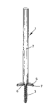
The drawings show a fixation pin 1 which consists
essentially of a smooth-walled shank part 2, adjoining which
there is a threaded part 3, the outside diameter of this
threaded part 3 being smaller than the outside diameter of
the shank part 2. Between the threaded part 3 and the shank
part there is in this way developed a conical step 4 which,
on the one hand, serves as abutment for the bone fragment B_
held by the threaded part against the main bone A but, on the
other hand, is able to penetrate slightly into the bone
fragment B_.
In order to give an idea of the order of magnitude, it
is pointed out that such a fixation pin 1 can, for instance,
have a length of 100 mm, the threaded part 3 having a length
of 15 mm and the shank part 2 a length of 85 mm. The
diameter of the threaded part can be 1.6 mm when the diameter
of the shank part 2 is 2 mm, or if the diameter of the shank
part is 1.6 mm then the threaded part has a diameter of 1.2
LAWYERS' AND MERCHANTS' TRANSLATION BUREAU INC.
Legal, Financial, Scientific, Technical and Patent Translations
Tel: (212) 344-2930/2931 11 BROADWAY, NEW YORK, NY I(?004 Fax: (212) 422-6877
Consultant Founded in 1903 by
WM. BERTSCHE, J.D., CH.E., A.C.S. CARL V. BERTSCHE

~1~6~~~
~V TRANSLATION
_ from:
mm.
Of course, larger diameters of the shank part and of the
threaded part are also possible.
The thread of the threaded part can preferably be
developed as a fine-pitch thread so that even small bone
splinters can be fastened with it. In this connection, the
thread is, of course, preferably of self-tapping type.
The shank part can easily be cut by suitable pliers so
that protruding regions can easily be removed.
Fig. 3 shows a fixation pin which bears a support disk
5. This support disk 5 has a -- preferably central -- hole 6
through which the threaded part 3 of the fixation pin 1 can
engage, the support disk 5 being then fixed to the step 4 of
the fixation pin 1.
In order to obtain a reliable and good fixation, the
hole 6 is developed in a manner which is in accord with the
conical development of the step 4, so that the step 4 rests
snugly in the hole.
In this connection, the support disk 5 is slightly
arched and its concave side is directed towards the bone to
be fixed in position, the edges 7 of the support disk 5 being
preferably also rounded so that no sharp edges which might
result in injuries are present. In this connection, it is
possible to maintain support disks of different size and
different convexity in stock.
LAWYERS' AND MERCHANTS' TRANSLATION BUREAU INC.
Legal, Financial, Scientific, Technical and Patent Translations
Tel: (212) 344-2930/2931 I 1 BROADWAY, NEW YORK, NY 10004 Fax: (2l2) 422-6877
Consultant Founded in 1903 by
WM. BERTSCHE, J.D., CH.E., A.C.S. CARL V. BERTSCHE

2~3~~~2
TRANSLATION _ 6 _
from:
While in the embodiment shown in Figs. 3 and 4, the
support disk 5 can slide freely on the threaded part and
adapts itself only via a corresponding conical recess to the
conical support step, it is also possible, in practice, for
the support disk to have within the region of the hole an
internal thread which is adapted to the external thread of
the threaded part of the fixation pin so that, in this way,
the support disk can be screwed onto the threaded part of the
fixation pin.
LAWYERS' AND MERCHANTS' TRANSLATION BUREAU INC.
Legal, Financial, Scientific, Technical and Patent Translations
Tel: (212) 344-2930/2931 I I BROADWAY, NEW YORK, NY 10004 Fax: (212) 422-6877
Consultant Founded in 1903 by
WM. BERTSCHE, J.D., CH.E., A.C.S. CARL V. BERTSCHE

Representative Drawing
A single figure which represents the drawing illustrating the invention.
Administrative Status

2024-08-01:As part of the Next Generation Patents (NGP) transition, the Canadian Patents Database (CPD) now contains a more detailed Event History, which replicates the Event Log of our new back-office solution.

Please note that "Inactive:" events refers to events no longer in use in our new back-office solution.

For a clearer understanding of the status of the application/patent presented on this page, the site Disclaimer , as well as the definitions for Patent , Event History , Maintenance Fee  and Payment History  should be consulted.

Event History

Description Date
Inactive: Expired (new Act pat) 2014-03-19
Inactive: Office letter 2007-09-27
Revocation of Agent Requirements Determined Compliant 2007-09-27
Appointment of Agent Requirements Determined Compliant 2007-09-27
Appointment of Agent Request 2007-08-21
Revocation of Agent Request 2007-08-21
Inactive: Office letter 2007-03-01
Inactive: Corrective payment - s.78.6 Act 2007-01-25
Inactive: IPC from MCD 2006-03-11
Inactive: Entity size changed 2002-03-06
Grant by Issuance 2000-08-22
Inactive: Cover page published 2000-08-21
Pre-grant 2000-05-26
Inactive: Final fee received 2000-05-26
Notice of Allowance is Issued 1999-11-29
Letter Sent 1999-11-29
Notice of Allowance is Issued 1999-11-29
Inactive: Application prosecuted on TS as of Log entry date 1999-11-25
Inactive: Status info is complete as of Log entry date 1999-11-25
Inactive: Approved for allowance (AFA) 1999-11-03
All Requirements for Examination Determined Compliant 1995-02-13
Request for Examination Requirements Determined Compliant 1995-02-13
Application Published (Open to Public Inspection) 1994-09-29

Abandonment History

There is no abandonment history.

Maintenance Fee

The last payment was received on 2000-02-22

Note : If the full payment has not been received on or before the date indicated, a further fee may be required which may be one of the following

  • the reinstatement fee;
  • the late payment fee; or
  • additional fee to reverse deemed expiry.

Please refer to the CIPO Patent Fees web page to see all current fee amounts.

Fee History

Fee Type Anniversary Year Due Date Paid Date
MF (application, 4th anniv.) - standard 04 1998-03-19 1998-02-23
MF (application, 5th anniv.) - standard 05 1999-03-19 1999-02-24
MF (application, 6th anniv.) - standard 06 2000-03-20 2000-02-22
Final fee - small 2000-05-26
MF (patent, 7th anniv.) - standard 2001-03-19 2001-02-27
MF (patent, 8th anniv.) - standard 2002-03-19 2002-02-25
MF (patent, 9th anniv.) - standard 2003-03-19 2003-02-24
MF (patent, 10th anniv.) - standard 2004-03-19 2004-02-25
MF (patent, 11th anniv.) - standard 2005-03-21 2005-02-24
MF (patent, 12th anniv.) - standard 2006-03-20 2006-02-24
2007-01-25
MF (patent, 13th anniv.) - standard 2007-03-19 2007-02-23
MF (patent, 14th anniv.) - standard 2008-03-19 2008-02-22
MF (patent, 15th anniv.) - standard 2009-03-19 2009-02-23
MF (patent, 16th anniv.) - standard 2010-03-19 2010-02-22
MF (patent, 17th anniv.) - standard 2011-03-21 2011-02-21
MF (patent, 18th anniv.) - standard 2012-03-19 2012-02-28
MF (patent, 19th anniv.) - standard 2013-03-19 2013-02-22
Owners on Record

Note: Records showing the ownership history in alphabetical order.

Current Owners on Record
DIETMAR PENNIG
Past Owners on Record
None
Past Owners that do not appear in the "Owners on Record" listing will appear in other documentation within the application.
Documents

To view selected files, please enter reCAPTCHA code :


To view images, click a link in the Document Description column. To download the documents, select one or more checkboxes in the first column and then click the "Download Selected in PDF format (Zip Archive)" or the "Download Selected as Single PDF" button.

List of published and non-published patent-specific documents on the CPD .

If you have any difficulty accessing content, you can call the Client Service Centre at 1-866-997-1936 or send them an e-mail at CIPO Client Service Centre.


Document
Description 
Date
(yyyy-mm-dd) 
Number of pages   Size of Image (KB) 
Cover Page 1995-10-15 1 77
Claims 1995-10-15 2 162
Abstract 1995-10-15 1 53
Drawings 1995-10-15 1 55
Description 1995-10-15 6 499
Description 1999-11-01 6 212
Claims 1999-11-01 2 58
Cover Page 2000-08-04 1 28
Representative drawing 2000-08-04 1 5
Representative drawing 1999-05-20 1 4
Commissioner's Notice - Application Found Allowable 1999-11-29 1 164
Correspondence 2000-05-26 2 57
Fees 2004-02-25 1 18
Correspondence 2007-03-01 1 12
Correspondence 2007-03-01 1 16
Correspondence 2007-08-21 2 65
Correspondence 2007-09-27 1 12
Correspondence 2007-09-27 1 15
Fees 1997-03-27 1 83
Fees 1997-02-28 1 39
Fees 1996-03-08 1 45
National entry request 1994-11-24 2 101
International preliminary examination report 1994-11-24 179 478
Prosecution correspondence 1994-11-24 5 183
Prosecution correspondence 1995-02-13 1 26
Prosecution correspondence 1998-05-06 1 38
Prosecution correspondence 1998-05-06 2 46
Examiner Requisition 1998-01-06 2 45