Note: Descriptions are shown in the official language in which they were submitted.
136gOU
FIELD OF THE lNV~NllON
The disclosed invention is directed to a method and
apparatus for inflating and curing a resin impregnated
liner user for rehabilitating and reinforcing an
underground manhole. More particularly, the disclosed
invention is directed to a method and apparatus for
simultaneously introducing through a common conduit
pressurized, heated air and steam into a resin
impregnated liner, so that the liner inflates and engages
the walls of the manhole and after which the liner is
cured for reinforcing and rehabilitating the manhole.
BACKGROUND OF THE INVENTION
Underground manholes and the like are frequently
formed from brick, cement, and like cementitious and/or
refractory materials. The manhole usually has a
relatively long neck portion extending from the surface,
and terminating in a lower sometimes flaring portion to
which a sewer pipe communicates. The sewage flowing
through the sewer pipe may, over time, damage the mortar
which secures the bricks of the manhole together, or the
cement with which the manhole is formed. Damage to the
bricks and cement will permit ground water and subsurface
water to infiltrate the manhole, with the result that the
water treatment plant may become overloaded and unable to
handle the amount of water which it receives during rain
and other such occurrences. In that event, either
untreated water is uncontrollably discharged, or the
2136900
water treatment plant itself becomes unable to perform
its function and needs to be taken out of service.
Replacement of a manhole is a relatively expensive
undertaking, because of the need to excavate the
surrounding soil, and remove the bricks and other
materials. In addition, the sewer itself must continue
to be usable during the procedure, or else homes and
businesses will be unable to flush toilets, run taps,
etc. For this reason, it is desireable to rehabilitate
and/or reinforce the manhole in a way which avoids a need
for replacement.
My prior patent, U.S. Patent No. 5,265,981, issued
November 30, 1993, the disclosure of which is
incorporated herein by reference, discloses a method and
apparatus for rehabilitation a manhole through use of a
resin impregnated fiberglass liner which is inflated and
cured in place while permitting the manhole to remain in
service as it is being rehabilitated. That patent
discloses the use of heated air to inflate the liner so
-that the surrounding walls of the manhole are engaged,
after which the resin cures and secures the liner to the
walls of the manhole. I have found that heated air can
take a relatively long period to achieve sufficient resin
cure. Particularly for deep manholes, the walls of the
manhole and the surrounding soil act as a heat sink which
tends to cool the resin, so that additional time for
curing is required ~ecause the surrounding material also
must be heated somewhat.
~136900
.
In view of the above, those skilled in the art will
understand that there is a need for a method and
apparatus which inflates the manhole liner ard achieves
cure of the resin more rapidly than may be accomplished
through use of heated air alone. The disclosed invention
meets these needs through the simultaneous introduction
of pressurized, heated air and steam through a common
conduit creating an extremely turbulent condition within
the inflated liner and causing the inflated liner to
resemble a convection oven.
OBJECTS AND SUMMARY OF THE INVENTION
The primary object of the disclosed invention is a
method and apparatus for simultaneously introducing
pressurized, heated air and steam into a resin
impregnated manhole liner to cause the liner to inflate
and engage the walls of the manhole, after which the
resin is relatively rapidly cured so that the manhole is
reinforced and/or rehabilitated.
- An apparatus for inflating and curing a liner
according to the invention includes an inflation canister
having a top plate and a cylindrical neck extending
therefrom. The neck is attachable to a liner which is to
be inflated and cured within the manhole. A firs~
conduit is secured to the top plate and therethrough
communicates with the neck. The conduit includes means
for simultaneously permitting pressurized air and steam
to flow therethrough and thereby to a liner attached to
~13690~
the neck. A relief valve is operably associated with the
plate for maintaining the liner thereafter at a selected
pressure.
A method for inflating and curing a resin
impregnated liner comprises the steps of lowering a resin
impregnated liner into an underground structure so that a
portion of the liner extends beyond the structure. The
liner portion is then sealed. Pressurized air and steam
are then simultaneously admitted into the liner, so that
the liner inflates and engages the walls of the
structure. Air and steam continue to be admitted into
the liner thereafter for a period sufficient to cure the
resin while the liner is engaged with the structure.
The method of reinforcing a manhole according to the
invention comprises the steps of providing a liner shaped
to conform to a manhole to be reinforced. The liner has
first and second resin impregnated layers sandwiching an
impermeable layer. An impermeable bladder overlies the
first layer. The liner is lowered into the manhole, and
~ portion of the liner extends therefrom. The liner
portion is then sealed. Heated, pressurized air and
steam are simultaneously admitted into the liner, so that
the liner inflates and the second layer engages the walls
of the manhole. Heated, pressurized air and steam
continue to be admitted into the liner for a period
sufficient to cure the resin in the layers.
These and other objects and advantages of the
invention will be readily apparent in view of the
; ~13690~
following description and drawings of the above-described
invention.
DESCRIPTION OF THE DRAWINGS
The above and other objects and advantages and novel
features of the present invention will become apparent
from the following detailed description of the preferred
embodiment of the invention illustrated in the
accompanying drawings, wherein:
¦ 10 Figure 1 is a cross-sectional view, partially in
schematic, of a liner being inflated and cured within a
manhole according the invention;
Figure 2 is a cross-sectional view similar to that
of Figure 1 after the liner has been cured;
Figure 3 is a perspective view of the inflation
canister of the invention;
Figure 4 is an exploded assembly view of a liner
according the invention; and
Figure 5 is a cross-sectional view of a liner being
-lowered into a manhole.
DESCRIPTION OF THE INV~NTION
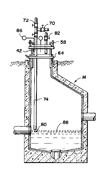
Manhole M, as best shown in Figures 1 and 2, is
formed from a cementitious material and has a wali
defining a top portion or neck 10 from which flaring
portion 12 and chamber portion 14 extend. Inlets 16 and
18 communicate with chamber portion 14 in order to permit
water to flow to the manhole M. Sewer line 20 is formed
-- ~136~0U
in floor 22 of manhole M, and permits water and waste
materials flowing into manhole M through inlets 16 and 18
to be communicated to a water treatment facility (not
shown) for treatment. In addition, sewer line 20 is
S usually also in communication with other manholes, so
that sewage flows from one manhole M to the next until
ultimately reaching the treatment facility.
Figure 4 discloses liner L which is used for
rehabilitating and reinforcing manhole M after any of the
neck 10, flaring 12 and chamber 14 portions have
deteriorated. Liner L includes structural fiberglass
layers 24 and 26 which sandwich fluid impermeable layer
28. Layers 24, 26, and 28 have an opening 30 formed
therein which corresponds to the shape and dimension of
sewer line 20 in floor 22. Bladder 32 is disposed over
layer 26 and closes opening 30, and is impermeable to
air, water, and like fluids in order to permit inflation
of liner L when positioned within manhole M.
I prefer that the fiberglass layers 24 and 26 be
impregnated with a two component epoxy resin system, such
as disclosed in my prior cited Patent No. 5,265,981. The
epoxy resin 34 impregnates the woven, structural
fiberglass of the layers 24 and 26 and, upon being cured,
provides a hard, rigid, reinforcing structure which is
secured to the walls of the manhole M. The epoxy resin
34 may be applied to each of layers 24 and 26 through
roller 36 or otherwise.
- - ~136~00
Support 38, as best shown in Figure 1, is positioned
within sewer line 20 to prevent the liner L and the
exposed portion of bladder 32 from blocking sewer line
20. Thus, even when the liner L is installed within the
manhole M of Figure 1, sewer line 20 remains open to
permit water flow therethrough for treatment. The liner
L does, however, close inlet lines 16 and 18 while
rehabilitation proceeds, so there may be a need for
diversion of water and/or installation during a time of
day at which little water flow occurs through the inlets
16 and 18.
Each liner L is manufactured to conform to the shape
and dimensions of the particular manhole M which is to be
reinforced. Proper reinforcement of the manhole M occurs
when the fiberglass layer 24 is pressed against the
surrounding wall of the manhole, so that the epoxy resin
34 may bond thereto and so that the rigid cured resin
will provide structural reinforcement.
once the liner L has been manufactured, its layers
-24 and 28 are impregnated with the epoxy resin, and it is
lowered lnto the manhole M. Liner L must then be
inflated in order to cause the liner to expand. I have
found that approximately 500 to about 1500 pounds per
square foot of pressure should be applied to forcè the
layers of the liner L against the wall of the manhole M.
In addition, the inflation pressure must be sufficient to
stop water infiltration at the bottom of the manhole M
that may occur due to ground water or other hydrostatic
~13~00
head. Thus, for example, should the vertical wall 40
have water throughout its height, then those skilled in
the art will understand that the hydrostatic head of the
water proximate the floor 22 may be sufficient to
separate the fiberglass layer 24 in that area from the
interior of the wall 40 if sufficient inflation pressure
is not present. Moreover, sufficient pressure should be
available in order to cause the resin 34 impregnating the
layer 24 to be forced into the fissures, openings, and
gaps in the exposed wall of the manhole M, thus
increasing the surface area available for securement.
As best shown in Figure 3, inflation canister C has
a cylindrical neck portion 42 from which upper flange
portion 44 radially extends. Opening 46 extends through
canister C for reasons to be explained. Protruding bead
48 extends about canister C proximate the lower end of
neck 42 in order to minimize the tendency of canister C
to be expelled from the liner L during the inflation and
curing process.
- Brackets 50 extend outwardly from neck 42, and I
prefer that there be at least three equiangularly
disposed brackets 50. Guides 52 are secured to each of
brackets 50 and a vertical leg 54 is moveable relative
thereto. Key 56 removably secures each of legs 54~
relative to its guide 52 in order to permit the canister
C to be set relative to the manhole M while taking into
account fluctuation in the surface surrounding neck
portion 10.
213~900
Clamps 58 are secured to flange portion 44 in order
to secure top plate 60 to flange portion 44 so that
opening 46 is sealed. I prefer that the top plate 60 be
~, a transparent material, such as Lexan, so that I may
observe the liner L during the inflation and curing
process. Although only two clamps 58 aré disclosed, I
provide a sufficient number about the flange portion 44
to keep the top plate 60 in its sealing position. The
clamps 58 may be nothing more than a C-clamp, or like
clamping device.
Once the liner L has been lowered into manhole M,
then a portion of the liner L extends upwardly beyond the
top 62 of manhole M. Tensionable belt 64 extends about
liner L above bead 48 in order to secure the liner L to
the neck 42 of canister C. The tensionable belt 64 may
be a webbed belt having a tensioning assembly 65
permitting the belt 64 to be rapidly tightened about the
neck 42 for securing the liner L to the canister C.
Cooperation of belt 64 with bead 48 prevents canister C
from separating from liner L on account of the inflation
pressure.
Top plate 60 has a plurality of openings formed
therein. T-connector or fitting 66 is secured to a first
of the openings in top plate 60, and valve 68 conerols
the opening. Valves 70 and 72 are provided at the ports
of the T-connector 66 in order to control fluid flow
therethrough to downpipe 74. Downpipe 74, as best shown
in Figure 1, extends from top plate 60 within liner L,
~136900
and has a discharge approximately 2-3 feet above the
floor 22 of manhole M. Downpipe 74 and T-connector 60
are manufactured from steel pipe, and are sized to permit
adequate flow to liner L to cause expansion thereof and
curing of the resin 34.
Steam generator 76 is in flow communication with one
of the ports of the T-connector 66 in order to provide
steam through downpipe 74 to the interior of liner L.
The steam injector 76 should create steam having a
temperature of about 300 F, well above the boiling point
of water, in order to provide wet heat for curing the
resin 34 of the liner L. A Karcher Model 950 generator
utilizing a 5.~ horsepower motor pumping water under
pressure through the boiler has been utilized.
Regenerative blower 78 is in flow communication with the
other port of T-connector 66 in order to provide heated,
pressurized air thereto for introduction into liner L
through the discharge 80 of downpipe 74. I prefer the
use of a regenerative blower, because the air while being
pumped is heated to about 210 F or more in excess of its
incoming ambient temperature. The regenerative blower 78
may be powered by a gasoline engine or an electric motor,
so that the blower turns at approximately 7,000 rpm.
Centrifugal and positive displacement pumps may arso be
used to create pressurized air, provided that heat
inversion and high injection velocity are achieved.
Because the steam from steam generator 76 and the
heated, pressurized air from the blower 78 are each
~136900
._
introduced to T-connector 66, then same mix together and
are injected into the liner L through the discharge 80.
Because of the downpipe 74, a fast moving column of a
!'~ hot, pressurized steam/air mixture is created, with the
temperature of the column typically reaching 270- F or
more. The injection of heated, pressurized air and steam
through the common downpipe 74 creates a very turbulent
environment within the interior of the liner L, with the
result that the hot pressurized steam/air mixture
communicates throughout the entirety of the inflated
liner L for applying penetrating heat to the resin 34
impregnating the layers 24 and 26. Because of the mass
of the water in the steam, then substantially more heat
is injected per unit time into the liner L for curing
purposes than could be accomplished through use of air
alone. Because of the air, however, the relatively heavy
steam propagates throughout the liner L while also
causing the liner L to be inflated so that the resin
impregnated layer 24 presses against the interior of the
manhole M. The combination of the heated, pressurized
air and the steam creates a convection oven which
significantly improves the curing process, and overcomes
the tendency of the soil S surrounding the manhole M from
cooling the resin. Thus, the resin 34 impregnatin`g the
fiberglass layers 24 and 26 more rapidly cures than is
otherwise available. I have found that complete resin
cure with the steam/air mixture is about four times
2136900
faster than using air alone and about twice as fast as
using steam alone.
As noted earlier, I regulate the inflation pressure
within the liner L sufficient to inflate the liner L and
prevent water infiltration into the manhole M. Relief
valve ~2 communicates with opening 46 in neck 42 through
top plate 60. The relief valve 82 may be a manually
operable valve which is opened and closed in response to
the pressure indicated on the pressure gauge 84, or it
may be a valve which is settable. In any event, relief
valve 82 causes pressurized air and/or water vapor to be
exhausted from the liner L, so that additional heated,
pressurized air and steam may be supplied thereto.
Figure 1 also discloses temperature gauge 86 which
monitors the temperature within the oven-like retort
created within the liner L.
I prefer that the discharge 80 of downpipe 74 be set
approximately 2-3 feet above floor 22 of manhole M. Due
to natural convection processes, condensate will
accumulate on bladder 32 due to water in the steam giving
up its heat to the surrounding layers, walls, and soil.
The water naturally will have a temperature of no more
than the boiling point of water, and I prefer that the
resin be cured to a temperature of at least 200 ~.
Placing the discharge 80 above the surface 88 of any
accumulated condensate, as best shown in Figure 2, will
minimize any further cooling of the steam as may occur
due to the steam being injected into the water. In
~13690U
addition, placing the discharge 80 above the surface 88
will naturally create turbulence within the condensate
due to the high velocity of the air/steam mixture This
helps to create a moist, penetrating heat within the
liner L.
Figure S illustrates use of the invention for
reinforcing and rehabilitating a brick manhole Ml.
Manhole M1 has bricks 90 arrayed in a series of courses,
with the surface 92 thereof having become badly pitted
and spalled. Liner L of Figure 5 corresponds to the
liner L of Figure 4, and has outer fiberglass layer 24,
bladder 32, and opening 30 adapted to reinforce the
manhole Ml while permitting sewer pipes 94 and 96 to
remain in service. It can be seen in Figure S that a
lS crane (not shown) has a cable 98 to which a hook 100 is
attached for connection to bracket 102 of lifting
assembly 104 secured to flange 44 by bolts. Unlike the
tensionable belt 64 of Figures 1 and 2, collar 106 may be
L used to secure the liner L to the neck 42.
After the liner L has been inflated and the resin
sufficiently cured in the manholes M and M1 of Figures 1
and 5, then the simultaneous injection of heated,
pressurized air through blower system 78 and steam from
steam generator 76 is terminated. Although I prefer T-
connector 66 for permitting steam and air to be admitted
to liner L, it is merely necessary that a multiple port
fitting or like means for simultaneously receiving the
fluids be used. Top plate 60 is then removed by
~136900
releasing the clamps 58 and canister C is disengaged from
liner L. Impermeable bladder 32 is then removed from the
liner L for reuse. Once the bladder 32 has been removed,
then the portion of the liner L above the surface 62 is
trimmed, and the portion of the liner L closing inlets 16
and 18 and to sewer pipe 20 removed. The resin
impregnated fiberglass layers 24 and 26 are sufficiently
rigid to reinforce the manhole M, and the layer 24 is
bonded to the surrounding wall of the manhole M or Ml in
order to keep the liner in position and prevent or
minimize future spalling. It will be understood that the
inner fiberglass layer 26 is relatively impervious to the
environment created within the manholes M and M1, so the
resulting life should be relatively long and require
little maintenance.
While this invention has been described as having a
preferred design, it is understood that it is capable of
further modifications, uses, and/or adaptations of the
invention following the general principle of the
-invention and including such departures from the present
disclosure as come within known or customary practice in
the art to which the invention pertains, and as may be
applied to the central features hereinbefore set forth,
and fall within the scope of the invention of the limits
of the appended claims