Language selection

Search

Patent 2137014 Summary

Third-party information liability

Some of the information on this Web page has been provided by external sources. The Government of Canada is not responsible for the accuracy, reliability or currency of the information supplied by external sources. Users wishing to rely upon this information should consult directly with the source of the information. Content provided by external sources is not subject to official languages, privacy and accessibility requirements.

Claims and Abstract availability

Any discrepancies in the text and image of the Claims and Abstract are due to differing posting times. Text of the Claims and Abstract are posted:

  • At the time the application is open to public inspection;
  • At the time of issue of the patent (grant).
(12) Patent: (11) CA 2137014
(54) English Title: CONDENSING HEAT EXCHANGER SCRUBBER SYSTEM
(54) French Title: SYSTEME EPURATEUR POUR ECHANGEUR DE CHALEUR A CONDENSATION
Status: Expired and beyond the Period of Reversal
Bibliographic Data
(51) International Patent Classification (IPC):
  • F28B 1/02 (2006.01)
  • B01D 53/18 (2006.01)
  • F01K 19/00 (2006.01)
  • F28B 9/08 (2006.01)
  • F28F 13/00 (2006.01)
  • F28F 27/02 (2006.01)
(72) Inventors :
  • WILLIAMS, PAUL J. (United States of America)
(73) Owners :
  • THE BABCOCK & WILCOX COMPANY
(71) Applicants :
  • THE BABCOCK & WILCOX COMPANY (United States of America)
(74) Agent: SMART & BIGGAR LP
(74) Associate agent:
(45) Issued: 1999-02-02
(22) Filed Date: 1994-11-30
(41) Open to Public Inspection: 1995-06-03
Examination requested: 1994-11-30
Availability of licence: N/A
Dedicated to the Public: N/A
(25) Language of filing: English

Patent Cooperation Treaty (PCT): No

(30) Application Priority Data:
Application No. Country/Territory Date
161,109 (United States of America) 1993-12-02

Abstracts

English Abstract


A scrubber and heat recovery system for flue gas comprises
a housing having a cooling section and a condensing section. An
inlet is located near the cooling section and an outlet is
located near the condensing section for the entry and exit of
the flue gas. A cooling heat exchanger is located in the
cooling section and a condensing heat exchanger is located in
the condensing section for interactively contacting the flue
gas. A perforated tray is located in the condensing section at
the condensing heat exchanger for improving distribution of the
gas and providing additional contact surface.


French Abstract

Système d'épuration et de récupération de la chaleur des gaz de combustion. Le système comprend un logement doté d'une section de refroidissement et d'une section de condensation. Un orifice d'entrée est aménagé près de la section de refroidissement et un orifice de sortie se trouve près de la section de condensation. Ces deux orifices permettent aux gaz d'entrer dans le logement et d'en sortir. Un échangeur de chaleur de refroidissement est placé dans la section de refroidissement tandis qu'un échangeur de chaleur à condensation se trouve dans la section de condensation. Ces échangeurs sont en contact interactif avec les gaz de combustion. Un plateau perforé est placé dans la section de condensation au niveau de l'échangeur de chaleur à condensation en vue d'améliorer la répartition des gaz et d'offrir une surface de contact additionnelle.

Claims

Note: Claims are shown in the official language in which they were submitted.

- 5 -
C L A I M S:
1. A scrubber and heat recovery system for a flue gas,
the system comprising:
a housing having a cooling section and a
condensing section, the housing also having an inlet
near the cooling section and an outlet near the
condensing section;
heat exchanger means disposed in the cooling
section and the condensing section of the housing;
liquid means for providing a liquid to the heat
exchanger means;
A perforated tray disposed in the condensing
section at the heat exchanger means, the perforated
tray including a plate having a plurality of
apertures, and a plurality of baffles on the plate
defining a plurality of compartments;
the housing for receiving the flue gas at the
inlet, the flue gas being interactively contacted with
the heat exchanger means of the cooling section and
the heat exchanger means of the condensing section,
and the flue gas exiting the housing at the outlet.
2. The system according to claim 1, including treatment
means in the housing for cleaning a flue gas.

Description

Note: Descriptions are shown in the official language in which they were submitted.


;' ~,ASE 5419 ~
,
1 - 21~7Ql~
IMPROVED ~_Ol~v~ S ING ~T EXCHANGER
S~ ;K SYSTEM
FI~LD AND Rl~'R~O~ND OF TH~ lNV~.~lON
The present invention relates, in general, to the recovery
of heat from flue gas in scrubber systems, and in particular, to
a new and useful system for improving liquid and gas
distribution in a scrubber using a sieve tray.
In the power plant field, condensing heat exchangers have
been used for a number of years in order to recover heat from
the flue gas produced by boilers. Through the use of condensing
heat exchangers, some of the particulate, acid gases, metals and
toxics associated with the flue gas can be removed from the flue
gas.
A typical condensing exchanger-scrubber system consists of
a downflow gas cooling section and an upflow gas condensing
section. Reagent and/or additives are optional from improving
the removal e.fficiency of the .scrubbe~r systems.
The efficiency of the heat exchanger-scrubber system is
largely dependent upon the cooling and contacting of the flue
gas with the surface of the heat exchanger and the liquid
condensate, reagent, additives, etc.

'~ - 2 21~701~
However, presently, no known system or meth~d exists for
providing a uniform liquid and gas distribution at the condensing
heat exchanger.
~U~M~Y OF TNE INVENTlON
The present invention provides an improved condensing heat
exchanger scrub~ing system for flue gas which utilizes a perforated
tray in order to improve the distribution of the gas and provide
additional contact with condensate and~or reagent and/or additives
used in the scrubbing system.
The present invention comprises a heat recovery and scrubber
system comprising a cooling section and a condensing section. A
heat exchanger is located in the cooling section and the condensing
section. ~lue gas is passed into the system at the cooling section
for interactively contacting the heat exchanger, and in turn, is
passed through the system through the heat exchanger of the
condensing section in order to remove particulate, acids, metals
and toxics from the flue gas prior to the flue gas exiting the
system at an outlet near the condensing section.
~ he present invention includes a perforated tray in the
condensing section near the condensing heat exchanger for improving
gas distribution and adding contact surface through gas-liguid
froth which accumulates on the perforated tray. ~he perforated
tray is a sieve tray comprising a plate having a plurality of
apertures and is divided into a plurality of compartments through
the use of baffles on the plate.
Thus, in accordance with the present invention there is
provided a ~crubber and heat recovery system for a flue gas, the
system comprising a housing having a cooling section and a
condensing section, the housing al80 having an inlet near the
cooling section and an outlet near the condensing section; heat
exchanger means disposed in the cooling section and the condensing

- 2a - ~ ~ 3 ~
' ._
section of the housing; liquid means for providing a liquid
to the heat exchanger means; a perforated tray disposed in
the condensing section at the heat exchanger means; the
perforated tray including a plate having a plurality of
apertures, and a plurality of baffles on the plate defining
a plurality of compartments; and the housing for receiving
the flue gas at the inlet, the flue gas being interactively
contacted with the heat exchanger means of the cooling
section and the heat exchanger means of the condensing
section, and the flue gas exiting the housing at the outlet.
The various features of novelty which characterize the
invention are pointed out with particularity in the claims
annexed to and forming a part of this disclosure. For a
better understanding of the invention, its operating
advantages and specific objects attained by its uses,
reference is made to the accompanying drawings and
descriptive matter in which a preferred embodiment of the
invention is illustrated.

~ASE 5419
~ 1 370~ ~
BRIEF DESCRIPTION OF l~IE DRAWINGS
In the drawings:
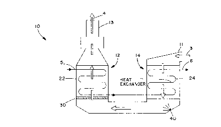
Fig. 1 is a schematic view of the present invention; and
~ig. 2 is a top view of the plate of Fig. 1.
5 DESCRIPTION OF THE PREFERRED ~MRODIME~S
Fig. 1 illustrates a heat exchanger and scrubber system,
generally designated lO, comprising a cooling section 14 and a
condensing section 12. Inlet 11 is located near the cooling
section 14 for the entry of unclean flue gas 3. A condensate
heat exchanger 22 is located in the condensing section 12 and a
cooling heat exchanger 24 is located in the cooling section 14.
A cool liquid 5 is provided to the heat exchanger 22 at the
condensing section 12, which is in turn provided to the heat
exchanger 24 after exiting the heat exchanger 22. The liquid
passed through the cooling heat exchanger 24 becomes a hot fluid
shown at 6 which exits from the system at the cooling section
14.
. Unclean flue gas 3 is provided to the cooling section 14
and interactively contacts the heat exchanger 24 for cooling the
flue gas 3. The flue gas is then passed to the condensing
section 12 for interactively contacting the condensing heat
ex~h~nger 22. Condensing heat exchanger 22 allows for
particulate, acids, metals and toxics to be removed from the
flue gas at the co~en~ing section 12 prior to exiting the
~ystem 10 at outlet 13 where it exits the system 10 as a clean
flue-gas 4.
Treatment means 40 is optionally included in the system 10
for providing reagent and/or additives for improving cont~m;n~nt
removal efficiency of the system 10.
A porous tray 30 is located in the condensing section 12
near the condensing heat exchanger 22 for providing an improved

, CASE 5419 ~i 3 7 o ~ 4
- 4
'~~contact surface for receiving condensate produced by the contact
of the flue gas with the condensing heat exchanger 22 Sieve
tray 30 provides an improved gas distribution by allowing the
accumulation of gas-liquid froth on the tray 30.
Fig. 2 shows the sieve tray 30 comprising a plate 32 having
a plurality of perforations or apertures 34. A plurality of
baffles 36 are arranged on the plate 32 which define a plurality
of compartments 38 which provide more uniform liquid and gas
distribution for the system 10. The sieve tray 30 can be
located at any position along the condensing heat exchanger 22
within the condensing section 12.
The present invention provides a condensing heat exchanger
scrubbing system 10 which utilizes the sieve tray 30 in order to
improve the distribution of gas and provide additional contact
surface for condensate and/or reagent and/or additives used in
the system 10. For wet spray power scrubber systems, the
present invention has proved to increase the removal of SO2,
particulate and acid gas as well as reduce cost associated with
reagent usage, recirculated liquor flow, power and capital
costs.
While specific embodiments of the invention have been shown
and described in detail to illustrate the application of the
principles of the invention, it will be understood that the
invention may be embodied otherwise without departing from such
principles.

Representative Drawing
A single figure which represents the drawing illustrating the invention.
Administrative Status

2024-08-01:As part of the Next Generation Patents (NGP) transition, the Canadian Patents Database (CPD) now contains a more detailed Event History, which replicates the Event Log of our new back-office solution.

Please note that "Inactive:" events refers to events no longer in use in our new back-office solution.

For a clearer understanding of the status of the application/patent presented on this page, the site Disclaimer , as well as the definitions for Patent , Event History , Maintenance Fee  and Payment History  should be consulted.

Event History

Description Date
Inactive: IPC from MCD 2006-03-11
Time Limit for Reversal Expired 2003-12-01
Letter Sent 2002-12-02
Grant by Issuance 1999-02-02
Pre-grant 1998-10-29
Inactive: Final fee received 1998-10-29
Notice of Allowance is Issued 1998-06-02
Letter Sent 1998-06-02
Notice of Allowance is Issued 1998-06-02
Inactive: Status info is complete as of Log entry date 1998-05-29
Inactive: Application prosecuted on TS as of Log entry date 1998-05-29
Inactive: IPC removed 1998-05-04
Inactive: IPC assigned 1998-05-04
Inactive: First IPC assigned 1998-05-04
Inactive: IPC removed 1998-05-04
Inactive: IPC assigned 1998-05-04
Inactive: IPC removed 1998-05-04
Inactive: IPC assigned 1998-05-04
Inactive: IPC removed 1998-05-04
Inactive: IPC assigned 1998-05-04
Inactive: Approved for allowance (AFA) 1998-04-29
Application Published (Open to Public Inspection) 1995-06-03
All Requirements for Examination Determined Compliant 1994-11-30
Request for Examination Requirements Determined Compliant 1994-11-30

Abandonment History

There is no abandonment history.

Maintenance Fee

The last payment was received on 1998-11-23

Note : If the full payment has not been received on or before the date indicated, a further fee may be required which may be one of the following

  • the reinstatement fee;
  • the late payment fee; or
  • additional fee to reverse deemed expiry.

Please refer to the CIPO Patent Fees web page to see all current fee amounts.

Fee History

Fee Type Anniversary Year Due Date Paid Date
MF (application, 3rd anniv.) - standard 03 1997-12-01 1997-11-19
Final fee - standard 1998-10-29
MF (application, 4th anniv.) - standard 04 1998-11-30 1998-11-23
MF (patent, 5th anniv.) - standard 1999-11-30 1999-11-03
MF (patent, 6th anniv.) - standard 2000-11-30 2000-11-02
MF (patent, 7th anniv.) - standard 2001-11-30 2001-11-01
Owners on Record

Note: Records showing the ownership history in alphabetical order.

Current Owners on Record
THE BABCOCK & WILCOX COMPANY
Past Owners on Record
PAUL J. WILLIAMS
Past Owners that do not appear in the "Owners on Record" listing will appear in other documentation within the application.
Documents

To view selected files, please enter reCAPTCHA code :


To view images, click a link in the Document Description column. To download the documents, select one or more checkboxes in the first column and then click the "Download Selected in PDF format (Zip Archive)" or the "Download Selected as Single PDF" button.

List of published and non-published patent-specific documents on the CPD .

If you have any difficulty accessing content, you can call the Client Service Centre at 1-866-997-1936 or send them an e-mail at CIPO Client Service Centre.


Document
Description 
Date
(yyyy-mm-dd) 
Number of pages   Size of Image (KB) 
Description 1998-04-01 5 204
Claims 1998-04-01 1 30
Abstract 1995-06-03 1 18
Cover Page 1995-07-14 1 16
Description 1995-06-03 5 197
Claims 1995-06-03 1 36
Drawings 1995-06-03 2 38
Representative drawing 1999-01-28 1 5
Cover Page 1999-01-28 1 47
Commissioner's Notice - Application Found Allowable 1998-06-02 1 164
Maintenance Fee Notice 2002-12-30 1 173
Correspondence 1998-10-29 1 42
Fees 1998-11-23 1 33
Fees 1997-11-19 1 31
Fees 1996-10-30 1 33
Courtesy - Office Letter 1995-01-23 2 60
Prosecution correspondence 1995-02-24 1 30
Examiner Requisition 1997-07-29 2 38
Prosecution correspondence 1998-01-29 2 67