Note: Descriptions are shown in the official language in which they were submitted.
I ,
F~ '
~.;=a,. ,
v~>'~~e'~ 93/24239 P~'/NL93/00113
Short title: Method and device for applying liquid
material, in particular a hot melt, by means
of a sequentially operating applicator to a
substrate
The invention relates to a method for applying a
material pattern by means of an applicator to a substrate
moving relative to said applicator, by way of a control
valve for liqu~.d material, in particular a hot melt, said
valve being controllable for opining and closing and being
connected to a material supply,'which material pattern in
the direction of movement is sub-divided into pattern parts
with slight spacing between them, and to a device for
carrying out said method.
Applying a liquid material, in particular a hot
melt; by means of an applicator to a substrate by way of a
control valve with controllable opening and closing is a
technique which is known per se.
So 1~ng as the speed of the material relative to
if the applicator remains blow certain values and the space
between the pattern parts is not too small, no particular
problems occur, despite the fact that, particularly in the
base of pneumatically operated va~.ves; for obtaining a
well-defined patternp i.e. not ragged, large~si2e air
20 supply and discharge ducts are needed in order to be able
to supply and evacuate the control air in a short time.
However, the situation changes when the relative
speed increases and the space between the pattern parts has
' ~ ~ ~ ~to 'be small.' Tn this case the time which elapses between,
25 quickly making the valud close and subsequently quickly
maleing the valve apera is too short to obtain a good ef f ect .
This problem occurs in particular in the case of
pne~zmati.cally controlled va~,vee, in the case of which con-
siderable quantities of fir have to be supplied or
30 discharged through large-si a ducts in order to obtain the
des~.red rapid opening and closing of the valves.
The object of the invention is to provide a
CA 02137147 2002-12-11
-2-
solution to this problem. According to the invention, for this purpose use is
made of at least
two control valves which axe connected to the material supply and are made to
open and close
sequentially .
If, for example, there are two control valves and the first of these two is
made to close
at the end of its working cycle through rapid evacuation of the control air,
and is not in a
position to allow material through again very shortly afterwards by being made
to open, the
function of said first valve is taken over by the second valve, which is made
to open at the
correct moment; during the open period of this second valve, therf; is an
opportunity for the
situation in the first valve to recover, and said first valve is ready for the
next working cycle
the moment the second valve is made to close. A very rapid and error-free
operation is
achieved in this way.
Of course, the principle according to the invention can also be applied to a
system with
more than two control valves - for example three or even four - which are
controlled
sequentially.
It is also possible to divide these valves into two or more sets, each set
comprising at
least two valves, and said sets being made to open and close sequentially. For
example, it is
possible to make an applicator interact with four or six control valves, sub-
divided into two or
three sets of two or three valves each, so that even in the case of an
applicator with a relatively
long nozzle a good effect remains guaranteed.
It is pointed out that an applicator with two control valves is known per se
from US-A-
4,735,169. In the case of this known device, however, these conixol valves are
made to open
and close simultaneously, so that the principle on which the invention is
based is not known
from this publication.
The invention is explained with reference to the drawing, :in which:
Figures la, 1b and lc give examples of patterns of
a liquid material, in particular a hot melt, to be applied
to a substrate;
Figure 2 shows diagrammatically a plant with which
the method according-to the invention can be used;
Figure 3 shows a time chart of the opening and
closing times of the valves used in the plant according to
Figure 2;
Figure 4 shows a perspective view of an applicator
suitable for use of the method according to the invention;
Figure 5 shows a diagrammatic view of a plant in
which the valves are sub-divided into two sets of three
valves each,.
In Figure la reference number 2a indicates the
outflow nozzle of an applicator, which is known per se and
is not shown in any further detail, for applying strips of
liquid material, in particular a hot melt, in a fixed
pattern to a substrate, which is considered to be the plane
of the drawing, three of which strips are shown and are
indicated by reference numbers 4a - 4c. The substrate must
move in the directian of the arrow 6 below the outflow
nozzle 2a at a speed of, for example, 100 m per minute,
thus 1,670 mm/sec, while the distance d between the
respective material strips can be 3 mm. This means in fact
that the time elapsing between the shutting off of the
material supply to the applicator opening 2 and the re-
opening of said supply must be no longer than 1.8 ms. The
length 1r is approximately 30 mm, corresponding to an
application time of ~pprox. 20 milliseconds.
~~igure 1b relates to the situation in which narrow
strips of material, indicated by sa-8e,;,mus,t be applied by
means of the~nozzle 2b to the substrate. The distance 12
between the longitudinal edges of each material strip is in
this case equal to the space d2 between the respective
material stripe: Here again, therefore, a period of only
1.8 ms is available for both the supply period of the
material and the period in which the material supply is
interrupted.
Finally, Figure 1c shows by way of example how a
regular pattern of rows of material points 12a...12d, each
~. 3'~ ~ '~.
Sri
V~CD 9312239 PCT/NL93/001 r~~'
_ 4 _ i
with a length 1~ and a space d3 between them of approx. 3 mm
can be applied to a substrate with a single applicator
nozzle 2c, provided with a number of obstructions 10a-loc.
Here again, only 1.8 m~ is available as the time in which
the material supply takes place or is interrupted.
This cannot be achieved with the device according
to the prior art, but it can with the measures according to
the invention. The principle of the invention is explained
with reference to Figures 2 and 3.
20 Figure 2 shows diagrammatically an applicator 14,
the nozzle i6 of which lies a short distance above the
substrate 18 moving relative thereto and at right angles to
the plane of-.the drawing, The space 20 inside the appli
cator nozzle 22 is connected by means of two pneumatically
15' controlled control valves 24; 26 to the common material
supply line 28, through which the material, in particular a
hot melt, is supplied under the influence of the pressure
pump 30, under pressure from a source 32. The control valve
24 is pneumatically controlled by means of the line 34 by
20 the shuttle valve 36, the connection 36a of which is in
communiaataon by means of the line 38 with a pressure
medium source 40, and the connection ~6b of which opens out
into, the atmosphere, or can be connected to an air vent.
'The control valve 26 is controlled by means of he line 42,
25 by the shuttle valve 44, the connection 44a of which is in
communicaticin with the line 38, and thus with the pressure
medium source 40; while the connection 44b opens out into
the atmosphere.
The shuttle valve 36 and the shuttle valve 44 are
30; ro~trolled electrically by means of ~ontrol;~limes (46,;48
respectively] by a central control unit 50, which supplies
the shuttle valves 36 and 44 with the current pulses which
aye necessary for the:con~rol hereof.
The course of paid control pulses as a function of
35' time is indicated in Figuxe 3, in which figure the l2ne 3a
r~latas to the current pulses supplied to the shuttle valve
36, the line 3b relates to the current pulses supplied to
the shuttle valve 44, and the line 3c is the time axis. It
is assumed that during the current pulses applied to the
'.':
~~k. O 93/24239 P~'/hIL93/001~3
~ ~.
shuttle valves 36 or 44 the latter are controlled in such a
way that the control valve 24 or 26 controlled thereby is
open. The chart relates to the situation shown
diagrammatically in Figure 1a.
5 The control valve 24 thus opens at the moment t1
and closes at the moment t2p the time interval OT1
corresponds to the length 1~ of the materiel strip 4a in
Figure 1a. During this period of time, which can be, for
i
example, 20 ms, the material flows out of the nozzle
to aperture 2a.
At the moment t3, ~T2 after t2, for example 1.8 ms
after t2, the control salve 26 is opened. This situation
continues until the moment t4, ~T1 after t3, and during
this period the material is now supplied by means of the
control valve 26 to the outflow aperture 16 of the;nozzle
22, resulting in the material strip 4b. The function of the
material supply is then taken over again by the control
valve 24, which opens at the moment t5 and remains open
1 until the moment t6. The control valve 26 then takes over
the function of the control value 24.
zt is clear that with such a method of operation of
the applicator nozzle the two pne~.amatically operated
.
24 and 26 after closure have plenty of time
control valves
to move into a .table closed position in which transitional
phenomena have died QUt, and the valves are in a position
in which they can be opened reliably again in order to
i ensure the material supply.
Figure 4 shows how the control valves 24 and 26 can
be combined with the app~:icator nozzle 22 to form a
34 ,~constructiona:J- unit:. The various,supply,and cqntrol lines
:,
shown an this figure .
are a~ot
4
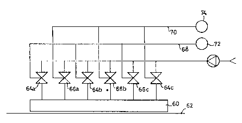
I Finally,'Figure 5 shows diagrammatically how, if
use zs Made of a relatively long applicator nozzle 60 lying
above ~.ize substrate 62, a uniformly distributed material
supply can be achieved through the use of more than two
control valves. In the case shown there are six of such
control ~ralves, sub-divided into two sets which are
indicated by 64a, 64b, 64c and 66a,'66b, 66c respectively.
The control valves 64a 64b, 64c are operated simultaneously
~'a ~3~~~~~' PC'TlNL93/OOI I
_ 6
by means of the common control line 68, and the control
valves 66a, 66b, 66c are operated simultaneously by means
of the control line ?0. The control line 68 corresponds,
for example, to the control line 34 in Figure 2, and the
control line ?0 corresponds to the control line 42 in
Figure 2. Line 68 is connected to the shuttle valve ?2, the
functioning of which corresponds to that of the shuttle
valve 36 in Figure 2, while line 70 is connected to the
shuttle valve ?4, the functioning of which corresponds to
that of the shuttle valve 44 in Figure 2. For the sake of
clarity, the remaining connections of said shuttle valves
are not shown.
It is clear that in the case in which the length 1"
13 of the material strips is considerably smaller than the
length 1y of the material strips shown in Figure lathe time
duration ~T1 of the respective control pulses will be
correspondingly shorter, but even then it remains long
enough to ensure good ~unGtioning.
.i . ~ n ~',