Note: Descriptions are shown in the official language in which they were submitted.
2137173
TERMINATION UNIT FOR TELECOMMUNICATION AND DATA LINES
The present invention relates to a termination
unit for telecommunication and data lines, in particular to
a termination unit having a removable access cover and
interior construction compatible with easy access to the
lines.
A termination unit of the foregoing type is known
in the art from German Patent No. DE 38 33 032 Al, granted
to Quante Fernmeldetechnik GmbH and published on April 5,
1990. The termination unit of that reference comprises
electrical plug connectors disposed in a frame mounted on a
housing wall, in order to permit a connection between tele-
phone or telecommunication installations and the electrical
wiring, the components or circuit arrangements being behind
the front portion. The electrical plug connectors inserted
in the frame comprise electrical components or circuits,
e.g. printed-circuit boards, that are required to permit an
interface between, for instance, a telephone handset and the
telephone wiring connected to the circuits. The telephone
handset is connected to the termination unit by a plug con-
nector, the plug of which is inserted into a plug socket in
the front panel. Prior art embodiments are complicated to
install and difficult to repair, if a fault occurs, and
require a large volume.
It is therefore the object of the invention to
simplify accessibility to the electrical plug connector of
the termination unit of the type referred to hereinabove.
213717~
In one form the invention is a termination unitfor telecommunication and data lines that comprises a front
portion provided with an insertion opening, a frame, an
electrical plug connector, a plug socket and clamping con-
tact elements for the lines. The front portion is built asa single piece with the frame, and has a removable access
cover. The electrical plug connector and the plug socket
are disposed on the rear side of the removable access cover
behind the insertion opening. A component unit is disposed
on the rear side of the front portion and connected to the
plug connector and the plug socket.
The plug connector and the clamping contract
elements may be built as a single unit that is disposed on
the rear side of the access cover. The plug connector may
be electrically connected to the plug socket by insulation
displacement contact elements. One set of insulation dis-
placement contacts of the insulation displacement contact
elements extends into the plug connector. Another set of
contacts of the insulation displacement contact elements
extends into the plug socket. Clamping contact elements or
disconnect contact elements are also provided in the area of
the plug connector.
The component unit may have insulation displace-
ment contact elements with contact tongues. The plug con-
nector and the component unit may be pluggably connected toeach other by the contact tongues of the component unit and
by the clamping contact elements or the disconnect contact
21~71 7~
elements of the plug connector. A disconnect plug may be
inserted into the disconnect contact element. The frame may
comprise on its front side behind the removable access cover
a forwardly open receiving portion into which the removed
access cover may be inserted when pivoted forward approxima-
tely 120. The frame may comprise a second removable access
cover behind which components supported in the frame are
freely accessible.
In another form the invention is a termination
unit for telecommunication lines, comprising a front portion
provided with an insertion opening, a frame, an electrical
plug connector, a plug socket and clamping contact elements
for the lines. The front portion is integrally constructed
with the frame, and the electrical plug connector and the
plug socket are disposed on the rear side of the front
portion behind the insertion opening.
The plug connector may be electrically connected
to the plug socket by insulation displacement contact ele-
ments. One set of insulation displacement contacts of the
insulation displacement contact elements extends into the
plug connector. Another set of contacts of the insulation
displacement contact elements extends into the plug socket.
Clamping contact elements or disconnect contact elements are
also provided in the area of the plug connector.
The plug connector and a component unit may be
pluggably connected to each other. That connection may be
by means of the contact tongues of the component unit and by
2 l 37~-73
the clamping contact elements or the disconnect contact
elements of the plug connector. The component unit may have
insulation displacement contact elements with contact ton-
gues. A disconnect plug may be inserted into the disconnect
contact element.
By the features of the termination unit of this
invention, accessibility to the plug connector mounted
behind the insertion opening of the front portion as well as
to the component unit optionally disposed in the frame is
substantially facilitated, when the access cover or the
front portion respectively, is removed.
The invention will next be described by means of
several preferred embodiments, utilizing the accompanying
drawings, in which:
Fig. 1 is a front view of the termination unit of
a first embodiment of the subject invention;
Fig. 2 is a perspective view of the termination
unit of Fig. 1, the access cover having been removed;
Fig. 3 is a perspective rear view of the access
cover of Fig. 2;
Fig. 4 is a perspective front view of the termina-
tion unit of Fig. 1, the access cover having been inserted
for line connection;
Fig. 5 is a perspective rear view of the termina-
tion unit of Fig. 4, the access cover not being shown;
- 2~3~ 73
Fig. 6 is a perspective front view of a second
embodiment of the termination unit, an upper access cover
and lower access cover both having been removed;
Fig. 7 is a perspective rear view of the component
unit of the electrical plug connector;
Fig. 8 is a perspective front view of the compo-
nent unit of Fig. 7;
Fig. 9 is an exploded perspective view of a plug
connector with plug socket embodiment that has additional
clamping contacts;
Fig. 10 is a perspective view of the plug connec-
tor with plug socket of Fig. 9, after assembly;
Fig. 11 is an exploded perspective view of another
plug connector with plug socket embodiment that has
additional clamping contacts;
Fig. 12 is a perspective view of the plug connec-
tor with plug socket of Fig. 11, after assembly;
Fig. 13 is an exploded perspective view of another
embodiment of the component unit;
Fig. 14 is a perspective view of an assembly of
the assembled plug connector of Fig. 10 in spaced relation
with the assembled component unit of Fig. 13; and,
Fig. 15 is a perspective view of the assembly of
Fig. 14 in conjunction with a front portion of the termin-
ation unit.
The first embodiment of the termination unit, as
illustrated in Figs. 1 to 5, comprises a frame 1 formed of
~1~7~ 73
moulded plastic, with a front portion 2 and a removable
access cover 3 attached to the front portion 2 by means of
screws 4. The access cover 3 has an insertion opening 5
which permits access to a plug connector 12 having a plug
socket 6 for receiving a telephone jack plug (not shown).
The front portion 2 can be mounted with the rest of frame 1
in a conventional housing or flush with a housing wall.
Fig. 2 illustrates the front portion 2 with the
access cover 3 removed. The access cover 3, shown in Fig.
3, is rotated so that its rear side is visible. Removal of
access cover 3 from front portion 2 exposes two lateral
spaced console portions 7 of the front portion 2. Each of
the console portions 7 has an upwardly-extending threaded
projection 9 that is internally threaded to accept one of
the screws 4 for attaching the access cover 3. At an end of
each console portion 7 is a moulded receiving portion 11
that is directed towards the bottom edge of front portion 2,
and whose purpose will be subsequently described. On the
back side, an integral part of the plastic moulded frame 1
is a box-type shell 8.
Fig. 3 shows that plug connector 12 is disposed on
the rear side of the access cover 3, which has a border
strip 10. Even a telephone subscriber may easily remove the
access cover 3. The plug connector 12 has a moulded plastic
housing 21 with contact slots 13 into which insulation
displacement contact elements (IDC contacts) are arranged,
as described in more detail in European Patent No. 0 445 376
2 1~7~7~
A1. The plug connector 12 further comprises a guide frame
14 with a multitude of elongated metal contacts 15 in
grooves 18 formed in the guide frame 14. The contacts 15
extend from one side of the plug socket 6 that receives the
telephone jack plug (not shown), to the opposite side of the
plug connector 12. The contacts 15 can contact other com-
ponents, as is described subsequently.
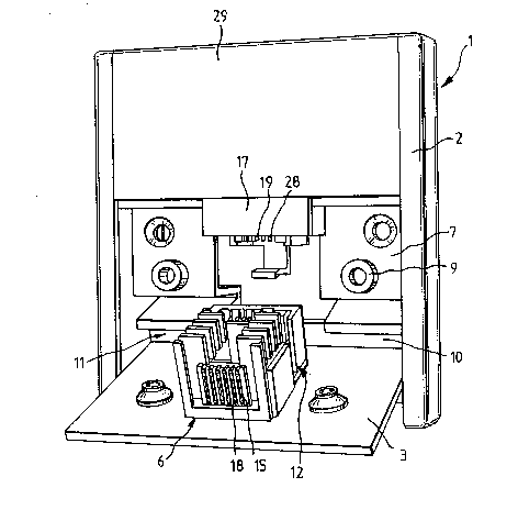
Figs. 2, 4 and 5 show that the upper portion 16 of
the front portion 2 carries a component unit 17 on its rear
side, as shown in more detail in Figs. 7 and 8. The
component unit 17 is formed of a moulded plastic housing 22,
and comprises grooves 28 in its lower section for receiving
contact fingers 19 that are in contact connection with the
contacts 15 in the grooves 18 of the guide frame 14 of the
plug connector 12. The moulded plastic housing 22 further
has a chamber 20 for receiving additional electrical
components, in particular, a capacitor and resistor unit.
Above the capacitor and resistor unit, the moulded plastic
housing 22 has a space 23 for a gas-discharge tube 24, and
disposed thereabove are connection elements 25 for connec-
tion with the ends of the communication wiring. The
elements 25 are screw connections or IDC contacts.
Fig. 8 shows that the leads 27 of the contact
fingers 19 of the component unit 17 extend from the lower
portion of unit 17 upwards within moulded channels 26, and
terminate in the connection elements 25. At intermediate
positions, leads of the contact fingers 19 branch away and
are in contact with the capacitor and resistor unit in the
chamber 20, and with gas-discharge tube 24.
The rear side of the front portion 2 is moulded as
a box-type shell 8, having portions which connect by a snap
connection with correspondingly-shaped parts of the housing
22 of component unit 17. The plug connector 12 is attached
to the rear side of the access cover 3 for the convenience
of telephone subscribers. The arrangement is of particu-
larly effective modular design, allowing extreme ease of
assembly and, in case of fault, disassembly. The removable
access cover 3 can be positioned for access by a subscriber
at the front portion 2, in the manner shown in Fig. 4. The
access cover 3 is arranged such that it is held in the lower
section of the front portion 2, in the moulded receiving
portion 11. Border strip 10 is guided into the receiving
portion 11, and held intermediate of the side walls of box-
type shell 8. In this arrangement, a subscriber does not
need to hold the access cover 3, and has both hands free to
connect wiring to the insulation displacement contact
elements (IDC contacts) of the plug connector 12.
Fig. 6 represents a further embodiment of the
termination unit, wherein the connection elements 25 that
receive the wiring are accessible from the front of the unit
after removal of a second access cover 29 forming the upper
part of the front portion 2 (Fig. 1). Removal of the second
access cover 29 makes the gas-discharge tube 24 accessible
to an engineer, without the need to remove the complete
- 21371 7~
front portion 2. This has the other advantage that the
engineer has both hands free to perform his job.
Figs. 9 and 10 illustrate another embodiment of
the plug connector 12 and the plug socket 6.
The exploded Fig. 9 view shows the plug connec-
tor 12 with a chamber 35, insulation displacement contact
elements 30, additional clamping contact elements 32, and
the plug socket 6. Into the contact slots 13 of the plug
connector 12 are respectively inserted the insulation
displacement contacts 31, and into the contact slots 18 of
the plug socket 6 are inserted the contacts 15 of the
insulation displacement contact elements 30. Additional
clamping contact elements 32 are arranged in the chamber 35
of the plug connector 12 such that an electrical connection
between the plug connector 12 with the plug socket 6 and the
component unit 17 can be established.
Fig. 10 shows the assembly of the individual
elements of Fig. 9, in particular, the easy accessibility to
the insulation displacement contact elements 32 in the
chamber 35.
Figs. 11 and 12 show an embodiment of the plug
connector 12 with the plug socket 6, with additional dis-
connect contact elements 37 in the chamber 35.
The exploded view of Fig. 11 shows the plug con-
nector 12 with the chamber 35, the insulation displacementcontact elements 38, the disconnect contact elements 37, and
the plug socket 6.
-- 2137~ 73
The insulation displacement contact elements 38 of
the plug connector 12 are respectively inserted such that
their insulation displacement contacts 31 extend into the
contact slots 13, and the bent-off contact legs 39 extend
into chamber 35 in the area of the plug connector 12. The
contact elements 40 are inserted such that their contacts 15
extend into the plug socket 6, and their bent-off contact
legs 41 extend into the chamber 35 to form with the bent-off
contact legs 39 the disconnect contact elements 37. The
disconnect contact elements 37 can be used for measurement,
test, separation, fault detection, or the like.
From the assembled representation of Fig. 12 it is
obvious that an easily-accessible disconnect position is
achieved by the disconnect contact elements 37 in chamber
35. Disconnect plugs (not shown) can be introduced into the
disconnect position.
Fig. 13 shows an embodiment of the component unit
17 in which insulation displacement contact elements 34 have
contact tongues 33 (Fig. 14). The contact slots 36 of the
insulation displacement contact elements 34 serve to connect
components, such as fuse elements, surge resistors or the
like. The contact tongues 33 enter the contact slots of the
clamping contact elements 32 of the plug connector 12, and
establish electrical contact between the plug connector 12
and the plug socket 6, as illustrated in Fig. 14.
Fig. 14 illustrates a connection between the plug
connector 12, the plug socket 6, and the component unit 17
- ` 21371~3
by the additional clamping contact elements 32. Instead of
the clamping contact elements 32, the disconnect contact
element 37 may be inserted into the chamber 35.
Fig. 15 illustrates the connection of the
component unit 17 with the plug connector 12 and the plug
socket 6, a front portion 43 being connectable as one piece
to a frame. The front portion 43 has an insertion opening
5. Behind the insertion opening 5 the plug socket 6 can be
latched in by means of various latch elements 42. After
removal of the front portion 43, all components are easily
accessible and can be replaced if defective.
The present invention therefore provides a ter-
mination unit having a modular design, and comprising an
electrical plug connector 12 and plug socket 6, and an
optional component unit 17 connected to the respective front
portion 2 or 43 by snap connections. The invention allows
for easy assembly and disassembly, for replacement of the
electrical plug connector 12 and the component unit 17. It
is also possible to receive two or more plug connectors 12
with associated plug sockets 6 and component units 17 in the
termination unit.