Note: Descriptions are shown in the official language in which they were submitted.
21 3720 4
SELF ALIGNING REMOVABLE BEARING CARRIER
FOR A LIQUID RING VACUUM PUMP
FIELD OF THE INVENTION
The present invention relates to liquid ring vacuum pumps
or compressors, and more particularly to a bearing housing
structure and a method for easy and accurate installation of
bearings, as well as quick removal and reinstalling of bearings
to their original alignment in the case of bearing failure on
an operating pump or other emergency.
BACKGROUND OF THE INVENTION
A liquid ring vacuum pump or compressor apparatus has
sequentially an inlet segment, a compression segment, a
discharge segment, and a seal segment. The pump includes a
generally annular housing having a longitudinal axis; a rotor
shaft journaled for rotation in bearings within fixed bearing
housings external to the pump housing; a rotor mounted on the
shaft for rotation within the housing and having radially
extending vanes forming a plurality of working chambers;and a
r
yaw ~a~
2~3,~~0~
Attorney s Docket 1625
port-containing cone member through which a pumped medium is
admitted to and discharged from the working chambers. Pump
heads which include fixed bearing housings have the advantage
that the bearing location is fixed radially in relation to the
axis of the cone, for control of centered position of the rotor
mounted on the shaft in relation to the cone mounted on the
head. Pump heads with a fixed bearing design have the
disadvantage that it is necessary to disassemble the pump to
change the bearing. This bearing change procedure is time
consuming and costly, especially if the pump is required for
production.
Removable bearing brackets on prior and current pump
designs have made it possible to change a bearing without
disassembling the pump. This has been desired when considering
making a quick change of bearings on a pump that is installed
for production.
When major bearing failure causes damage to the bearing
housing, a removable bearing bracket can be replaced and save
the expense of replacing an entire head.
In the past, liquid ring vacuum pumps have incorporated
removable bearing brackets of various designs. The most common
design is a four arm design mounted to the side of the head.
The plane of interface between this bearing bracket and head is
vertical and perpendicular to the axis of the pump. The
weakness of the design is the lack of positive reference to the
center of the cone mounted in the head and the lack of control
of infinite number of radial misalignment positions of the shaft
relative to the center of the cone mounted on the inside of the
2
2I37~0~
Attorney s Docket 1625
head, in the reassembly of the pump. Another weakness of four
arm design is that all the static load is held by bolts parallel
to the axis of the pump. The tightness of these bolts holds the
alignment position of the bearing bracket to the head.
In US Design Patent 297,942, the inventor, Somarakis, has
the bearing bracket interface to the head on a single horizontal
plane. This single reference plane controls the elevation of
the bearing, but uses machined circles, with inherent
tolerances, in each bearing bracket to independently control
both the horizontal position, and axis angle in aligning each
end of the shaft to the central axis of the cones mounted in the
heads. These same machined circles, with their inherent
tolerances, in each bearing bracket control the axial in and out
position of the two bearing centers. All of the vertical static
load is supported and transferred from the bracket to the head
in a horizontal plane and parallel to the axis of the pump.
DESCRIPTION OF THE PRIOR ART
Applicants are aware of the following U. S. Patents
concerning liquid ring pumps:
US Pat. No. Inventor Issue Date Title
Des. 297,942 Somarakis 10-04-1988 B E A R I N
G
HOUSING
496,347 Copeland 04-25-1893 JOURNAL
BEARING
1,350,245 Stachowski 08-17-1920 BEARING
1,678,968 Allen 07-31-1928 TURBINE
CYLINDER
SUPPORT
3
~~37zo~.
Attorney s Docket 1625
1, 743, 683 Payne Ol-14-1930 D R I V I N
G
MECHANISM FOR
SNOWPLOWS
2,191,890 Le Bus 02-27-1993 SHAFT BEARING
4,004,644 Liljekvist Ol-25-1977 ROLLER CUTTER
4,747,752 Somarakis 05-31-1988 SEALING AND
D Y N A M I
C
OPERATION OF
A LIQUID RING
PUMP
Somarakis U.S. Design Patent 297,942 teaches an ornamental
design for a bearing housing for a liquid ring vacuum pump.
Note that this design does not have any provision to be self-
aligning.
Copeland U.S. Patent 496,347 teaches a journal bearing.
There is no mention of any application to liquid ring vacuum
pumps. A claim is made that the invention will self-adjust the
axle or shaft but unlike Applicants' invention, no provision is
made for self alignment of the device itself.
Stachowski U.S. Patent 1,350,245 teaches an apparatus for
a frangible bearing bracket which is designed to break when the
load support from the shaft becomes excessive in order to save
the more expensive parts of the bearing. Note that this unit'
incorporates at least five separate pieces and does not have a
self-alignment feature.
Allen U.S. Patent 1,678,968 teaches an apparatus for
turbine-cylinder support. It is obvious from the drawings of
this patent does not relate to a liquid ring vacuum pump nor is
the support disclose, a unitary member.
4
_. 2~3'~20~.
Attorney s Docket 1625
Payne US Patent 1,743,683 teaches a drive mechanism for
snow plows this unit is not designed for use with liquid ring
vacuum pumps, nor is the bearing bracket of unitary design.
Le Bus US Patent 2,191,890 teaches a shaft bearing. Note
that this bearing shaft has only horizontal bolt holes
configured for accepting vertical bolts.
Liljekvist US Patent 4,004,644 teaches an apparatus for a
roller cutter and has no applications to liquid ring vacuum
pumps or bearing brackets configured to journal a shaft.
Somarakis US Patent 4,747,752 shows the current state of
the art in bearing housings for liquid ring vacuum pumps as
depicted in Figures 1 and 2 therein.
SUMMARY OF THE INVENTION
The invented removable bearing bracket includes a pair of
cylindrical aligning guides which provide horizontal as well as
vertical support. The removable bearing bracket provides an
axial stop at one end with the vacuum pump's receiving bracket
providing another axial stop.
Alignment of the bearing to the central axis of the two
cones of the pump is controlled by the cylindrical fit of the
guide members. The fit is machined and tight, the cylindrical
guides will not accept the bracket unless it is aligned axially
correct when it is inserted into the guide receiving means on
the vacuum pump. The mounting plate stop member, vertical and
5
2~3720~.
Attorney s Docket 1625
perpendicular to the central axis controls the in and out axial
position of the bearings, and maintains the specified distance
between the two bearing centers.
All of the vertical static load is supported and
transferred from the bearing bracket to the head in a
combination of horizontal and angular planes while keeping the
load support parallel to the axis of the pump.
OBJECTS OF THE INVENTION
The principal object of the invention is to provide a self-
aligning, removable bearing bracket for a horizontal shaft.
It is also an object of this invention to provide means for
positively controlling the alignment of a removable bearing
bracket or housing without requiring the use of special tools.
It is also an object of the invention to provide
self-aligning or self centering of the two bearing housing
bores, which is also the shaft centerline, to the centerline of
the cones.
It is also an object of the invention to provide by the
shape of the cylindrical guide, gravity force to work to
self-align or self-center the bearing bores even during
operation subjected to vibrations.
Another object of the invention is to provide positive
axial, in and out, location of bearing housing to the head.
6
2.~3'~20~.
Attorney s Docket 1625
Another object of the invention is to provide a relatively
small (in relation to head size) cast bearing housing that is
simple to repair or relatively inexpensive to replace if
severely damaged beyond repair.
It is also an object of the invention to provide a pump
housing head in which the working part is separable from the
support parts.
BRIEF DESCRIPTION OF THE DRAWINGS
The foregoing and other objects will become more readily
apparent by referring to the following detailed description and
the appended drawings in which:
Figure 1 is an isometric view of a bearing bracket in
accordance with the invention.
Figure 2 is a left hand end view of a vacuum pump with the
invented bearing housing installed on the end thereof.
Figure 3 is a right hand end view of the vacuum pump of
Figure 2 without the invented bearing housing installed on the
end thereof.
Figure 4 is a side view of the liquid ring vacuum pump
shown in Figure 2.
Figure 5 is a side view of the liquid ring vacuum pump of
Figure 2 with the bearing housing removed from the right side
7
2~3~~~~
Attorney s Docket 1625
thereof.
Figure 6 is an enlarged side view of a portion of the
liquid ring vacuum pump and bearing bracket shown in Figure 4.
Figure 7 is an isometric view of an alternative embodiment
of the invented bearing bracket showing the lubrication port.
Figure 8 is an isometric view of an alternative embodiment
of the invented bearing bracket shown in Figure 7, having a
modified central alignment member.
DETAILED DESCRIPTION
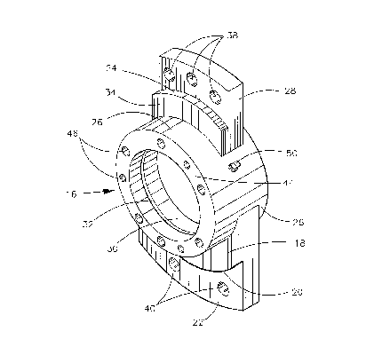
Referring now to the drawings, a liquid ring pump 10
includes a shaft 12 connected to an associated drive means, not
shown, the shaft extending along a longitudinal axis through
pump housing 14. The shaft is journaled for rotation in bearing
housings 16 mounted on the head 17 at each end of the pump
housing.
The invented bearing housing 16, as best shown in Figure 1,
has a bearing mounting 26 and two associated vertical mounting
plates 22 and 28. Each mounting plate has a lip 18 and 34 with
a smooth, preferably machined, cylindrical surfaces. Depending
upwardly from vertical mounting plate 28, lip 34 has a top
surface 24 extending upwardly to form a cylindrical engagement
member. Depending upwardly from the vertical mounting plate 22,
is lip 18 which has a bottom surface 20. Horizontal mounting
means such as bolt holes 40 are provided on each side of the
8
2137~0~
Attorney s Docket 1625
vertical mounting plate 22. Three such vertical holes 40 are
shown in the mounting plate 22, however more or less mounting
holes may be used, if desired (see Figure 2). Upstanding from
base 18 and aligned on the vertical axis of the bearing housing
are bearing mounting 26 and associated vertical mounting plate
28. Bearing mounting 26, which extends beyond mounting plate 28
as shown in Figure 1, and includes a cylindrical bore 30 having
a lubrication groove 32 therein for oil or grease. The
lubrication groove 32 is accessible through lobe port 50. Top
mounting holes 38 are provided in the vertical mounting plate
above the bore and on the vertical centerline of the housing 16,
as shown in Figure 1.
Machined bearing mounting face 44 is provided with holes 46
for installation of a bearing cap on the bearing housing, holes
46 preferably being threaded to receive bolts.
Housing 16 rests between bearing support heads 62 and 66,
Figure 3, which have a smooth, preferably machined, cylindrical
top and bottom surfaces for receiving mating bases 34 and 18.
The interplay of smooth, machined, cylindrical surfaces on
the bearing bracket and vacuum pump transfers the static and
dynamic load of the bearing to the head. These bearing surfaces
are clean, machined surfaces with no gaskets. Continuous
contact of the bearing bracket to the mating and supporting head
surface insures equal distribution of load, with minimal
distortion of the bracket under dynamic loading, and maintains
the engineered standard fit as originally manufactured.
The pair of cylindrical surfaces at the back of the
9
21~720~
Attorney s Docket 1625
bracket control an infinite number of points on the cylindrical
surfaces 20 and 24 which are equidistant from a point that
coincides with the centerline of the shaft and cone. A
sufficient axial length of engagement between the two
cylindrical mating surfaces on the bracket 20 and 24, Figure 6
mating with bearing support heads 62 and 66, to provide a close
tolerance fit, producing both radial and angular self alignment
with no additional external adjustment. The depth of
cylindrical surfaces 20 and 24 are must be greater than the
tolerance of the circular fit however much greater depths do not
produce any benefit as the alignment of the bracket. Therefore
in a typical application the depth of a quarter (1/4) inch (.635
centimeters) may be sufficient whereas a depth of two (2) inches
(5.08 centimeters) or more would not provide any alignment
benefit.
The pair of cylindrical surfaces at the back of the bracket
control the side to side position or horizontal alignment of the
bearing in relation to the central axis of the internal
operating cones of the pump, as well. The two concentric
cylindrical surfaces, having been machined for a very close
tolerance fit, provide radial and angular self-alignment when
cylindrical surfaces 20 and 24, Figure 1, is assembled into
cylindrical receiving surfaces 62 and 66, Figure 3. There is
rotational movement about the axis which allow precise alignment
with the bolt holes.
The upper and lower cylindrical alignment members 34 and
18, Figure 1, are attached to mounting plates 28 and 22, which
in conjunction with pump surfaces 68 and 60, control the in and
out position or axial distance alignment of the bearing in
.. 2I37~p~
Attorney s Docket 1625
relation to the end to end separation of the two internal
operating cones of the pump.
In operation, the bearing bracket is situated with
cylindrical positioners 34 and 18, Figure 1, in between faces 66
and 62 of bearing supports 68 and 60, Figure 5. This allows
cylindrical surface 24 to be in direct contact with face 66 of
bearing support 68 and cylindrical surface 20 to be in direct
contact with face 62 of bearing support 60 as shown in Figure 6.
Mounting plates 28 and 22, Figure 1, provide an axial stop
along with bearing supports 68 and 60, Figure 3. The bearing
housing is then fixed to the pump by placing bolts through holes
38 and 40, Figure 1, in the vertical mounting plates 28 and 22
and securing them to the pump in bolt receptacles 70 and 64,
Figure 3. The housing 16 is properly aligned for operation
without necessity for further action as shown in Figure 2. If
it becomes necessary to replace a bearing or housing during
operation, the procedure is the same, which assures accurate
alignment at all times.
The attachment locations 64 and 70 form a trapezoid within
which nearly all of the torque forces are situated, which helps
to stabilize the pump when in operation.
ALTERNATIVE EMBODIMENTB
Alternatively, the invented bearing housing 116, as best
shown in Figure 7, has a base or pedestal 118 with a smooth,
preferably machined, bottom surface 120 on its underside.
Extending downwardly from the base 118 is an angled central
11
21 372 0 4
Attorney s Docket 1625
axial aligner member 122. The angle ~ can vary from 30 to 60
degrees from the horizontal, but generally is 45 degrees. The
total angle a can vary from 60 to 120 degrees, but generally is
90 degrees. Depending downwardly from each side of the pedestal
and flanking the central aligner 122 are locator stops 124a and
124b. Upstanding from pedestal 118 and aligned on the vertical
axis of the bearing housing are bearing mounting 126 and
associated vertical mounting plate 128. Bearing mounting 126,
which extends beyond mounting plate 128, includes a cylindrical
l0 bore 130 having a lubrication groove 132 therein for oil or
grease. Lubrication groove 132 is accessible through lube port
150. A top mounting hole 138 is provided in the vertical
mounting plate above the bore and on the vertical centerline of
the housing 116. Vertical mounting means such as bolt holes 140
are provided on each side of the pedestal 118. Four such
vertical holes 140 are shown in the pedestal base, however only
two may be provided, if desired, one at each end of the
pedestal. The self alignment means for this bracket are more
fully described in US Patent No. 5,328,274 issued July 12,
1994.
Machined bearing mounting face 144 is provided with holes
146 for installation of a bearing cap on the bearing housing,
holes 146 preferably being threaded to receive bolts.
A further alternative bearing housing 116, as best shown in
Figure 8, is configured with a base or pedestal 118 having a
smooth, preferably machined, bottom surface 120 on its
underside. Extending downwardly from the base 118 is an angled
central axial aligner member 152 configured as a trapezoid with
a flat bottom 154.
12
2.~~'~~0~
Attorney s Docket 1625
SUMMARY OF THE ACHIEVEMENT
OF THE OBJECTS OF THE INVENTION
From the foregoing, it is readily apparent that we have
invented an improved self-aligning, removable bearing bracket
for a horizontal shaft, means for positively controlling the
alignment of a removable bearing bracket or housing without
requiring the use of special tools, and means for eliminating
radial misalignments of such bearings.
It is to be understood that the foregoing description and
l0 specific embodiments are merely illustrative of the best mode of
the invention and the principles thereof, and that various
modifications and additions may be made to the apparatus by
those skilled in the art, without departing from the spirit and
scope of this invention, which is therefore understood to be
limited only by the scope of the appended claims.
13