Note: Descriptions are shown in the official language in which they were submitted.
2 ~1 3 ~ 3 3 ~
Descrlptlon
MOUNTING ASSEMBLY FOR RECIPROCATING SLAT CONVEYOR
Technical Field
This invention relates to systems for mounting
reciprocating slat conveyors and the drive assemblies thereof
and, more particularly, to such a system in which a drive frame
assembly has a transverse drive frame member with a
strengthened central portion to which the end of a drive unit
is secured, and opposite side portions that are bendable
relative to the central portion to permit adjustment of the
vertical position of the outer ends of the side portions
relative to the drive unit when the assembly is mounted on a
structure.
Backqround Information
Reciprocating slat conveyors are used in various types of
installations and may be mounted on different kinds of
structures. One example of a structure into which a
reciprocating slat conveyor may be incorporated is a trailer.
Reciprocating slat conveyors are typically mounted on an
existing trailer or other structure, rather than being
manufactured together with the structure itself as an original
part of the structure. Therefore, it is desirable for a
conveyor to be relatively easy to mount onto a structure and
have some flexibility in adjusting to variations in the
dimensioning of the structure. Ease and flexibility in
mounting is preferably accomplished while also achieving and/or
maintaining compactness and strength in the drive assembly of
the conveyor.
'~
~373~8
Drive frame assemblies for reciprocating slat conveyors are
disclosed in my United States Patents No. 4,712,467, granted
December 15, 1987; No. 4,748,893, and No. 4,748,894, both
granted June 7, 1988; and No. 4,821,868, granted April 18,
1989. Each of these patents shows an assembly having opposite
end frame members to which the opposite ends of drive units are
secured. The use of ball blocks that receive the ball ends of
drive units to mount the drive units onto drive frame members
is illustrated in my U.S. Patents No. 4,817,783, granted
April 4, 1989; No. 4,969,389, granted November 13, 1990; No.
5,096,356, granted March 17, 1992; No. 5,125,502, granted
June 30, 1992; No. 5,165,524, granted November 24, 1992; and
No. 5,193,661, granted March 16, 1993.
Summary of the Invention
A subject of the invention is a reciprocating slat conveyor
comprising a plurality of conveyor slats and a conveyor drive
for moving the slats in a first direction, for conveying a
load, and for retracting the slats in the opposite direction.
The conveyor drive includes a piston-cylinder drive unit
positioned below the conveyor slats. The drive unit includes
a movable portion connected to the slats and a fixed portion
having a mounting end part. A main frame is positioned below
the conveyor slats. A transverse drive frame member is
positioned below the slats and is connected to the main frame.
The transverse drive frame member has a central portion and
opposite side portions extending laterally outwardly from the
central portion, each to an outer end. The mounting end part
of the drive unit is connected to the central portion of the
transverse drive frame member.
The opposite side portions of the transverse drive frame
member are preferably bendable in position relative to the
~central portion of the frame member to permit adjustment of the
vertical position of the outer ends to accommodate variations
in vertical spacing of the drive unit relative to portions of
the main frame that are connected to the outer ends. In its
preferred form, the transverse drive frame member includes a
2137338
generally horizontal metal plate having a central portion
provided with a plurality of strengthening ribs extending
longitudinally of the conveyor, and opposite side portions that
form said opposite side portions of the transverse drive frame
member. The ribs are preferably provided by forming the metal
plate to include a plurality of corrugations extending
longitudinally of the conveyor generally in line with the drive
units. The corrugations have end portions confronting and
connected to the mounting end part of the drive unit. The
corrugations carry axial drive forces generated by the drive
unit. In conveyors with a plurality of drive units, a mounting
end part of each of the drive units is preferably connected to
the end portions of the corrugations.
The conveyor may be provided with additional features: A
preferred additional feature is a stiffening beam firmly
connected to end portions of the corrugations for stiffening
the corrugations and the central portion of the metal plate.
Preferably, the corrugations are positioned longitudinally
between two such transverse beams. The side portions of the
plate remain free of connection to the transverse beam or beams
so that they are bendable in position relative to the
corrugations and the transverse beams.
The mounting end part of the drive unit may be connected
to the transverse drive frame member in various ways. The
preferred manner of connection comprises providing the drive
unit with a ball end, positioning the ball end in a cavity in
a ball block, and firmly connecting the ball block to the
transverse drive frame member. This preferred type of
connection has the advantage of being a secure connection that
efficiently transmits loads and that also permits some lateral
adjustment of the relative positions of the drive units and the
transverse drive frame member to compensate for misalignments
between the drive unit axis and the conveyor slats. When the
ball block is connected to the central portion of a metal
plate, it also serves to stiffen the central portion. In the
preferred embodiment of the conveyor, both ends of each drive
unit are provided with a ball end that is mounted to an end
21~73~8
frame member by means of a ball block. In addition, the ball
blocks at one end of the drive units each include a plurality
of passageways for delivering fluid pressure to, and returning
fluid pressure from, the ball end, for moving the conveyor
slats in the first direction and retracting the conveyor slats
in the opposite direction.
Another subject of the invention is a method of mounting
a reciprocating slat conveyor on a structure, said structure
including a main frame having laterally spaced apart portions.
The method comprises providing a conveyor drive including a
piston-cylinder drive unit having a movable portion and a fixed
portion with a mounting end part. A drive frame is also
provided and includes a transverse drive frame member having
a central portion and opposite side portions extending
laterally outwardly from the central portion, each to an outer
end. The method includes stiffening the central portion of the
transverse drive frame member, but allowing the side portions
to be bendable in position relative to the central portion to
permit vertical adjustment of the outer ends of the side
portions relative to the central portion. The mounting end
part of the drive unit is connected to the central portion.
The outer ends of the side portions are connected to the spaced
apart portions of the main frame. When the outer ends are
being connected, they are positioned vertically to bring them
into engagement with the spaced apart portions. A plurality
of conveyor slats are positioned above the drive unit, the main
frame, and the transverse drive frame member and are connected
to the movable portion of the drive unit.
The method preferably further includes one or more
preferred features. Such features include providing the
transverse drive frame member in the form of a corrugated metal
plate and stiffening the central portion of the plate with one
or more transverse beams, as described above. They also
include connecting the mounting end part of the drive unit to
the transverse drive frame member by means of a ball block,
also as described above.
21373~8
Another subject of the invention is a drive frame assembly
for a reciprocating slat conveyor. According to an aspect of
the invention, the assembly comprises a drive frame and a
conveyor drive for moving conveyor slats in a first direction,
for conveying a load, and for retracting the conveyor slats in
the opposite direction. The drive frame includes first and
second transverse drive frame members, which are longitudinally
spaced apart. Each of these frame members includes a generally
horizontal metal plate having a central portion and opposite
side portions extending laterally outwardly from the central
portion, each to an outer end. The frame member has stiffening
portions that stiffen the central portion of the metal plate.
The conveyor drive includes a plurality of separate
piston-cylinder drive units. Each drive unit includes a
movable portion and a fixed portion. The movable portion is
connectable to a set of conveyor slats. The fixed portion has
a first mounting end part and a second mounting end part
opposite the first mounting end part. The first and second
mounting end parts are connected to the central portions of the
metal plates of the first and second frame members,
respectively. The opposite side portions of each metal plate
are bendable in position relative to the central portion of the
plate to permit adjustment of the vertical positions of the
outer ends relative to the drive units when the assembly is
mounted on a structure by securing the outer ends to portions
of the structure.
According to another aspect of the invention, the drive
frame assembly comprises a drive frame having first and second
longitudinally spaced transverse drive frame members connected
to each other by a pair of laterally spaced longitudinal drive
frame members, and a conveyor drive for moving conveyor slats
in said first and opposite directions. The drive includes a
plurality of separate piston-cylinder drive units. The movable
portion of each drive unit is connectable to a set of conveyor
slats. Its fixed portion has opposite ball ends. Each ball
end is received in a ball block that is firmly connected to the
respective transverse drive frame member, to secure each drive
2137338
unit to both transverse drive frame members. Preferably, the
transverse drive frame members have stiffened central portions
and bendable side portions, as described above.
In the system of the invention, the various features result
in ease and flexibility in mounting the conveyor drive assembly
onto a structure, compactness and strength in the drive
assembly, and simplicity of structure and ease of maintenance
of the drive assembly. The preferred feature of the corrugated
metal plate with bendable side portions is a simple structure
but achieves a strong mounting for the drive units as well as
flexibility in mounting the drive assembly. When ball blocks
are used in combination with the corrugated metal plate, they
efficiently transmit loads to the corrugated central portion
of the plate to carry the axial drive forces generated by the
drive units. The preferred stiffening of the central
corrugated portion is also accomplished relatively simply in
the preferred embodiment by the use of a pair of transverse
beams. The overall result is a cost effective drive frame
assembly for a slat conveyor that is easily incorporated into
a structure onto which the conveyor is to be mounted.
These and other advantages and features will become
apparent from the detailed description of the best mode for
carrying out the invention that follows.
Brief Description of the Drawings
In the drawings, like element designations refer to like
parts throughout, and:
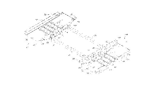
Fig. 1 is a pictorial view looking up at the preferred
embodiment of the drive frame assembly of the invention,
excluding the linear reciprocating motors thereof.
Fig. 2 is an exploded pictorial view of the assembly shown
in Fig. 1 but including the motors.
Fig. 2A is an enlarged pictorial view of one end portion
of the assembly shown in Fig. 2.
Fig. 3 is a bottom plan view of the assembly shown in Figs.
1-2A, with the clamps that connect the motors to the transverse
drive beams added.
2137338
Fig. 4 is a sectional view taken along the line 4--4 in
Fig. 3 and illustrating in phantom the bending of the side
portions of the metal plate.
Fig. 5 is a sectional view taken along the line 5--5 in
Fig. 3 with a plurality of conveyor slats shown in phantom.
Fig. 6 is like Fig. 1 except that it also includes the
motors and the hydraulic manifold.
Fig. 7 is a side elevational view of the drive frame
assembly shown in Fig. 6 and a portion of one of the main frame
beams to which the assembly is attached.
Fig. 8 is a partially schematic sectional view of the drive
frame assembly shown in Figs. 6 and 7 and additional portions
of the conveyor.
Fig. 9 is an exploded pictorial view of the preferred
embodiment of a set of three ball blocks.
Fig. 10 is a side elevational view of the one of the ball
blocks as shown in Fig. 9 with a ball end received therein.
Fig. 11 is a sectional view of the ball block and ball end
shown in Fig. 10, with the fasteners and ball block passageways
omitted.
Best Mode for Carrying out the Invention
The drawings illustrate the preferred embodiment of the
invention and the best mode for carrying out the invention
currently known to the applicant. A major focus of the
invention is the drive frame assembly, the preferred embodiment
of which is shown in Figs. 1-8. Figs. 9-11 illustrate the
preferred embodiment of the ball block of the drive assembly.
The invention encompasses a reciprocating slat conveyor
comprising a plurality of conveyor slats 2. The conveyor slats
2 may take various forms. Since the details of the structure
of the slats 2 are not a part of the present invention, the
slats 2 are shown schematically in Figs. 5 and 7. The slats
are preferably provided in a plurality of sets, with the
preferred number of sets being three.
The conveyor has a drive unit comprising a piston-cylinder
hydraulic motor 10, 20 for each set of slats 2. In the
~1373~8
preferred operation of the conveyor, the movable portions of
all three motors 10, 20 are moved in a first direction in
unison to convey a load. Then, the movable portions of the
motors are moved in an opposite direction, one at a time, for
returning the slats to a start position, one-third of the slats
at a time. This operational sequence is known and is described
in my U.S. Patent No. 5,193,661, cited above.
The conveyor also includes a transverse drive beam 4 for
each set of slats 2. See Fig. 8. In the conveyor illustrated
in the drawings, there are three transverse drive beams 4 each
of which is connected to its corresponding motor 10, 20 by
clamps 6. Each transverse drive beam 4 is also connected to
each slat 2 in its set of slats. Thus, the beam 4 transmits
movement of the motor 10, 20 to movement of the slats 2. The
details of the structure of the beams 4 and the manner of their
connections to the slats 2 and the motors 10, 20 form no part
of the present invention and may be varied considerably without
departing from the spirit and scope of the invention.
Preferably, the beams 4 are positioned close together above the
motors 10, 20 and are connected to the motors 10, 20 in the
manner shown in Fig. 8 and in my U.S. Patent No. 4,821,868,
cited above.
Referring to Figs. 1-8, the drive frame assembly comprises
a drive frame and a conveyor drive for moving the conveyor
slats 2 as described above. The conveyor drive includes at
least one drive unit and preferably includes three separate
piston-cylinder drive units, one for each set of conveyor slats
2. The drive units can be seen in Figs. 2, 2A, 3, and 6-8.
Each drive unit comprises a hydraulic motor having a movable
portion and a fixed portion. In the illustrated embodiment of
the conveyor drive, the cylinder 10 of each motor is movable
and is mounted on a fixed piston 20. In each motor, there are
two separate piston heads 22, and the cylinder 10 is divided
into two sections, to increase the effective pressure surface
area of the motor while maintaining a relatively small motor
diameter. This type of two-part motor is disclosed in my U.S.
Patent No. 4,748,893, cited above.
~ ~3733~
The details of one of the motors 10, 20 are shown partially
schematically in Fig. 8. Each half of the motor 10, 20
includes a piston rod 21 having at its opposite ends a piston
head 22 and a ball end 24, 26. Each ball end 24, 26 is mounted
onto the drive frame by means of a ball block 50, 52, as
described further below. The piston heads 22 are received into
their respective halves of the cylinder 10. The two portions
of the cylinder 10 are separated by a divider wall 14. In each
half of the cylinder 10, there is a first chamber 36 and a
second annular chamber 38. The first chamber 36 of each half
of the cylinder is connected by a conduit 16, 18 to the second
annular chamber 38 of the other half of the cylinder. This
achieves the desired increase in the effective pressure surface
area of the motor and also produces equal pressure surfaces for
movement of the cylinder in both directions. The piston rod
21 extends from the ball end 24, 26 into the cylinder. The end
of the cylinder through which the rod 21 extends is closed by
a cylinder head 12.
One of the ball ends 24 is provided with a plurality of
passageways for delivering hydraulic pressure to and returning
hydraulic pressure from the motor 10, 20. These passageways
are shown in Fig. 8 and schematically in Fig. 11. The other
ball end 26 is a closed blind end. The active ball end 24 has
a first passageway 28 which communicates with the first chamber
36 of the corresponding cylinder portion and, via conduit 18,
with the annular chamber 38 in the other half of the cylinder.
Hydraulic pressure introduced into passageway 28 causes the
cylinder to move to the left (as shown in Fig. 8). The ball
end 24 has a second passageway 30 which communicates with the
annular chamber 38 of its corresponding cylinder section and,
via conduit 16, with the chamber 36 in the other cylinder
section. Hydraulic pressure introduced into the passageway 30
causes the cylinder 10 to move to the right (as shown in Fig.
8). The motor 10, 20 is preferably provided with an internal
check valve 32 and associated passageway 34 of the type
disclosed in my U.S. Patent 5,325,763, and entitled
"Internal Check Valven.
.~
~ 9
2 93733~
The drive ~ystem shown in Fig. 8 also includes a check
valve 44 of the type disclosed and claimed in my U.S. Patent
No. 5,255,712. The valve 44 has a wire cable or rod 46
extending therefrom and terminating in an abutment 48.
Movement of the cylinder 10 all the way to the left (as shown)
causes an abutment on the cylinder, for example a portion of
the clamp 6, to contact the abutment 48 to open the check valve
44. The drive system also includes a number of additional
valves and controls that are housed in a manifold 94, shown in
Figs. 6-8. Valve 44 and the components housed in manifold 94
do not form a part of the present invention. An example of a
suitable combination of additional drive system elements is
disclosed in my U.S. Patent No. 5,193,661.
The piston-cylinder drive units are mounted on the drive
frame of the drive frame assembly. The drive frame includes,
at each of its opposite ends, a transverse drive frame member
64. The transverse drive frame members 64 are connected
together by a pair of laterally spaced, longitudinally
extending beams 90. These beams 90 may, for example, be formed
by square tubing. Each transverse member 64 comprises a
generally horizontal metal plate 66 having a central portion
and opposite side portions 74 projecting laterally outwardly
from the central portion. The side portions 74 terminate in
outer ends 76.
The central portion of the transverse drive frame member
64 is stiffened to resist bending. The central portion is
preferably provided with a plurality of ribs extending
longitudinally of the conveyor into which the assembly is
incorporated. In the preferred embodiment shown in the
drawings, the ribs are formed by a plurality of corrugations
68 formed in the central portion of the metal plate 66. The
stiffening of the central portion is accomplished by the
inclusion in the drive frame member 64 of two longitudinally
2~37~
spaced apart transverse beams 78, 80 and by the ball blocks 50,
52. A first transverse beam 78 extends along the outer end of
the metal plate 66 and is secured to outer end edge portions
of the central portion, including the corrugations 68, by
suitable means, such as welding W. This beam 78 has a C-shaped
cross section. The other transverse beam 80 has an L-shaped
cross section and extends along the inner edge of the plate 66.
The beam 80 has a horizontal leg 88 and a vertical leg 82. The
vertical leg 82 is secured, such as be welding W, to the
central portion of the plate 66, as shown in Figs. 1, 3, 5, and
6. The lateral side portions of the vertical leg 82 taper to
the laterally outer ends of the beam 80 to provide clearance
for mounting the drive assembly onto a main frame, as described
below. The tapering of the leg 82 is indicated by the
reference numeral 84. The longitudinal beams 90 that
interconnect the two transverse drive frame members 64 are
welded to the vertical leg 82, and gussets 92 are provided at
the connection to reinforce the connection.
The central portion of the metal plate 66 is provided with
a cut-out 70, best seen in Fig. 3. The vertical leg 82 of the
beam 80 has a corresponding cut-out 86. The cut-outs 70, 86
in the metal plate 66 and the beam leg 82 are aligned and
provide a recess for receiving a set of three ball blocks 50,
52. The three ball blocks S0, 52 are welded together and to
the inner end portions 72 of the corrugations 68 that confront
the drive units and form the inner edge of the recess. This
provides a secure mounting of the respective drive unit ends
to the transverse drive frame members 64. Along the inner edge
of each transverse drive frame member 64, the L-shaped beam 80
and the ball blocks 50, 52 cooperate to provide the desired
stiffening. In effect, the two components 50, 52 and 80
together form a transverse beam.
Each of the opposite side portions 74 of the metal plate
66 of each transverse drive frame member 64 is free of
connection to the stiffening members, i.e. the beams 78, 80 and
the ball blocks 50, 52. This allows the side portions 74 to
be bendable with respect to the central portion of the plate
2 ~733~
66, the stiffening members 78, 80, the ball blocks 50, 52, and
the motors 10, 20 mounted thereby.
Each ball block 50, 52 preferably has essentially the same
configuration as the ball block disclosed in my U.S.
Patent 5,350,054, entitled, "Ball Block for Mounting
Linear Motor~'. Since the details of the structure
of the ball block do not form a part of the present
invention, the ball block will only be briefly
described herein.
- Referring to Figs. 9-11, each ball block 50, 52 includes
an upper housing portion 50 and a lower housing po~tion 52.
Unlike the ball block shown in U.S. Patent 5,350,054,
the ball block in the conveyor drive of the
invention preferably has the overall square housing
configuration shown in the drawings herein. The two housing
portions are secured together by means of fasteners 54. The
upper housing portion 50 has an outer wall 56 which is secured
to the confronting end portions 72 of the corrugations 68, as
shown in Figs. 1, 3, and 5-8. The axis of each drive unit
extends through the outer wall 56 and is aligned with the
corrugations 68 to efficiently transmit loads to the transverse
drive frame member 64 and relieve loads on the fasteners 54,
as described in detail in my U.S. Patent 5,350,054. The
corresponding ball end 24, 26 is received into a cavity formed
by each ball block 50, 52. The piston rod 21 extends from the
ball end 24, 26 out of the ball block housing 50, 52 through
a passageway 58. A seal 60 surrounds the rod 21. Preferably,
a flange 62 extends upwardly from the lower housing portion 52,
as shown in Fig. 9. The flange 62 cooperates with the outer
wall 56 to form the socket into which the ball end 24, 26 is
received. On one end of the frame, each lower housing portion
52 includes a plurality of passageways for delivering fluid
pressure to, and returning fluid pressure from, the ball end
'1~
21~7338
24 received in the ball block 50, 52. The passageways
communicate with passageways 28, 30, 34 in the ball end 24.
The present invention encompasses a method of mounting a
reciprocating slat conveyor on a structure as well as the
conveyor itself and the drive frame assembly thereof. In the
method, the drive frame assembly of the conveyor is mounted by
attaching it to laterally spaced apart portions of a main frame
of the structure. The method is preferably practiced using the
preferred embodiment of the drive frame assembly shown in the
drawings and described above. The central portion of the metal
plate 66 is stiffened as described above, and the mounting end
parts, i.e. the ball blocks 50, 52, of the drive units are
secured to the central portion. The drive frame assembly is
positioned on the structure with the outer ends 76 of the metal
plate side portions 74 positioned over the laterally spaced
apart portions of the main frame. As shown in Figs. 3-5 and
7, these laterally spaced portions are upper portions of the
upper flanges of two I-beams 8.
When the assembly is mounted onto an existing structure,
there commonly is some variation in the vertical spacing of the
drive units relative to the upper flanges of the I-beams 8.
The upper flanges may either be slightly higher or slightly
lower than the unbent position of the metal plate side portions
74. Fig. 4 illustrates the bending of the side portions 74
relative to the central portion in order to accommodate the
variation in vertical spacing. The bending of the side
portions 74 brings the outer ends 76 of the side portions 74
into engagement with the spaced apart upper flange portions of
the I-beams 8. Then, the outer ends 76 are welded to the
I-beam flanges to secure the drive frame assembly to the main
frame of the structure. Thus, the freedom of the side portions
74 to bend relative to the central portion of the metal plate
66 and the stiffening elements of the transverse drive frame
member 64 permit the drive frame assembly to be easily
installed in any of a number of structures without requiring
difficult or complicated procedures or additional apparatus in
21~73~8
-- order to compensate for variations in the vertical positioning
of main frame elements of the structure.
The method of mounting the conveyor also includes
positioning the conveyor slats 2 above the drive units, the
main frame, and the transverse drive frame members 64. Each
set of conveyor slats 2 is connected to the movable cylinder
portion 10 of its corresponding drive unit. As illustrated,
this is accomplished by engaging the cylinder 10 with a pair
of clamps 6 that are secured to a transverse drive beam 4. The
slats 2 in the set are then, in turn, positioned above the
transverse drive beam 4 and secured thereto. Once the conveyor
has been installed, movement of the conveyor slats 2 during
operation of the conveyor may be guided and supported by
various known types of guide beams and bearings.
Although the preferred embodiment of the invention has been
illustrated and described herein, it is intended to be
understood by those skilled in the art that various
modifications and omissions in form and detail may be made
without departing from the spirit and scope of the invention
as defined by the following claims.
14