Language selection

Search

Patent 2137702 Summary

Third-party information liability

Some of the information on this Web page has been provided by external sources. The Government of Canada is not responsible for the accuracy, reliability or currency of the information supplied by external sources. Users wishing to rely upon this information should consult directly with the source of the information. Content provided by external sources is not subject to official languages, privacy and accessibility requirements.

Claims and Abstract availability

Any discrepancies in the text and image of the Claims and Abstract are due to differing posting times. Text of the Claims and Abstract are posted:

  • At the time the application is open to public inspection;
  • At the time of issue of the patent (grant).
(12) Patent: (11) CA 2137702
(54) English Title: INJECTION MOLDING NOZZLE WITH SEPARABLE CORE AND ONE-PIECE COLLAR
(54) French Title: BUSE POUR MOULAGE PAR INJECTION CONSTITUEE D'UN COLLIER MONOPIECE ET D'UN CORPS SEPARABLES;
Status: Term Expired - Post Grant Beyond Limit
Bibliographic Data
(51) International Patent Classification (IPC):
  • B29C 45/20 (2006.01)
  • B29C 45/27 (2006.01)
(72) Inventors :
  • GELLERT, JOBST ULRICH (Canada)
(73) Owners :
  • MOLD-MASTERS (2007) LIMITED
(71) Applicants :
  • MOLD-MASTERS (2007) LIMITED (Canada)
(74) Agent: SMART & BIGGAR LP
(74) Associate agent:
(45) Issued: 2004-11-02
(22) Filed Date: 1994-12-07
(41) Open to Public Inspection: 1996-06-08
Examination requested: 2001-12-05
Availability of licence: N/A
Dedicated to the Public: N/A
(25) Language of filing: English

Patent Cooperation Treaty (PCT): No

(30) Application Priority Data: None

Abstracts

English Abstract

An injection molding nozzle with an elongated body removably seated in a one-piece outer collar. The outer collar has a circular insulation flange which seats in the mold to locate the nozzle. The elongated body has an electrical heating element coiled around a central melt channel. Terminal portions of the heating element extend outwardly through a U-shaped opening in the outer collar into a ceramic connector. The connector is secured in place by an inner lip which slides into a groove around the U-shaped opening.


French Abstract

Une buse de moulage par injection avec un corps allongé logé de manière amovible dans une collerette extérieure d'une seule pièce. La collerette extérieure présente une bride d'isolation circulaire qui repose dans le moule pour positionner la buse. Le corps allongé a un élément chauffant électrique enroulé autour d'un canal de fusion central. Des parties terminales de l'élément chauffant s'étendent vers l'extérieur à travers une ouverture en forme de U dans la collerette extérieure vers l'intérieur d'un connecteur en céramique. Le connecteur est fixé en place par une lèvre intérieure qui coulisse dans une rainure autour de l'ouverture en forme de U.

Claims

Note: Claims are shown in the official language in which they were submitted.

10
The embodiments of the invention in which an
exclusive property or privilege is claimed is defined as
follows:
1. In an injection molding nozzle to be seated in a
mold, the nozzle having a melt channel extending
therethrough to convey melt frontwardly toward at least one
gate extending through the mold to a cavity, the nozzle
having an outer collar and an elongated central body with
a rear end, the outer collar extending around the central
body adjacent the rear end thereof and having a frontwardly
extending flange portion to be received in a seat in the
mold to locate the nozzle, the improvement wherein;
the elongated central body and the outer collar
are separable, the outer collar is one-piece with a central
hole therethrough and a rearward facing seat extending at
least partially around the central hole, the central body
having a central shaft portion with a rear flange portion
extending outwardly therefrom adjacent the rear end of the
central body, whereby the central body is removably seated
in the outer collar with the central shaft portion
extending through the central hole in the outer collar and
the rear flange portion sitting against the seat in the
central hole in the outer collar.

11
2. An injection molding nozzle as claimed in claim
1 wherein the central body has an integral electrical
heating element with at least one terminal portion
extending radially outwardly adjacent the rear end of the
central body, and the outer collar has a rear end and a U-
shaped opening extending therethrough adjacent the rear end
to receive the terminal portion of the electrical heating
element therethrough when the central body is received in
the outer collar.
3. An injection molding nozzle as claimed in claim
2 wherein the terminal portion of the electrical heating
element extends into a connector, the connector having an
inner end and an outwardly extending lip adjacent the inner
end, and the U-shaped opening has a groove extending
therearound from the rear end of the collar to receive the
outwardly extending lip of the connector to securely mount
the connector to the collar.

Description

Note: Descriptions are shown in the official language in which they were submitted.


~137'~~2
2
INJECTION MOLDING NOZZLE WITB SEPARABLE CORE
AND ONE-PIECE COLLAR
HACRGROUND OF THE INVENTION
This invention relates generally to injection
molding and more particularly to an injection molding
nozzle with an elongated central body removably seated in
a one-piece outer collar.
Injection molding nozzles having an integral
electrical heating element and a central bore for conveying
thermoplastic melt to a cavity in a cooled mold are well
known. In the past, these nozzles have either had a single
piece outer collar portion integrally brazed around an
elongated central body portion or a two-piece removable
outer collar in which a central body is seated. An early
example of an integral nozzle is shown in the applicant's
U.S. Patent Number 4,403,405 which issued September 13,
1983 and it has the disadvantage that the entire nozzle is

2137702
3
lost if the heating element malfunctions. An example of a
nozzle with a two-piece outer collar is shown in the
applicant's Canadian patent application serial number
2,127,211 filed June 30, 1994 entitled "Injection Molding
Nozzle with Removable Collar Portion". While this has the
advantage of being separable, it has the disadvantage and
added cost and difficulty of the collar being two-piece.
SOMMARY OF THE INVENTION
l0 Accordingly, it is an object of the present
invention to at least partially overcome the disadvantages
of the prior art by providing an injection molding nozzle
with an elongated central body removably seated in a one-
piece outer collar.
To this end, in one of its aspects, the invention
provides an injection molding nozzle to be seated in a
mold, the nozzle having a melt channel extending
therethrough to convey melt frontwardly toward at least one
gate extending through the mold to a cavity, the nozzle
having an outer collar and an elongated central body with
a rear end, the outer collar extending around the central
body adjacent the rear end thereof and having a frontwardly
extending flange portion to be received in a seat in the
mold to locate the nozzle, the improvement wherein the
elongated central body and the outer collar are separable,

213'702
4
the outer collar is one-piece with a central hole
therethrough and a rearward facing seat extending at least
partially around the central hole, the central body having
a central shaft portion with a rear flange portion
extending outwardly therefrom adjacent the rear end of the
central body, whereby the central body is removably seated
in the outer collar with the central shaft portion
extending through the central hole in the outer collar and
the rear flange portion sitting against the seat in the
central hole in the outer collar.
Further objects and advantages of the invention
will appear from the following description taken together
with the accompanying drawings.
BRIEF DESCRIPTION OF THE DRAWINGS
Figure 1 is a sectional view of a portion of a
multi-cavity injection molding system showing a nozzle
according to a preferred embodiment of the invention,
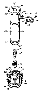
Figure 2 is an exploded isometric view showing
the components of the nozzle seen in Figure 1 in position
for assembly, and
Figure 3 is an isometric view showing the same
nozzle assembled.

2I3'~'~0~
DETAILED DESCRIPTION OF THE INVENTION
Reference is first made to Figure 1 which shows
a portion of a multi-cavity injection molding system or
apparatus in which several steel nozzles 10 are seated in
5 openings 12 in a mold 14 to convey pressurized plastic melt
through a melt passage 16 to respective gates 18 leading to
different cavities 20 in the mold 14. While the mold 14
usually has a greater number of plates depending upon the
configuration, in this case only a cavity plate 22 and back
l0 plate 24 which are secured together by bolts 26 are shown
for ease of illustration. The mold 14 is cooled by pumping
cooling water through cooling conduits 28 in the cavity
plate 22 and back plate 24.
The nozzles 10 are interconnected by a steel melt
distribution manifold 30 which is mounted between the
cavity plate 22 and the back plate 24 by a central locating
ring 32 and insulative and resilient spacer members 34.
The melt distribution manifold 30 is heated by an integral
electrical heating element 36 and an insulative air space
38 is provided between it and the surrounding cooled cavity
plate 22 and back plate 24. The melt passage 16 receives
melt from a molding machine (not shown) through a central
inlet 40 in a cylindrical inlet portion 42 of the manifold
and branches out in the manifold 30 to pass through a
25 central melt channel 44 in each of the nozzles 10. The

213772
6
melt then flows through an aligned melt duct 46 in a nozzle
seal 48 having a hollow inner piece 50 and a threaded outer
piece 52 to the gate 18.
Also referring to Figures 2 and 3, each nozzle to
has an elongated central body 54 removably seated according
to the invention in a one-piece outer collar 56. The steel
outer collar 56 has a central hole 58 extending
therethrough with a rearward facing seat 60 extending
partially around the central hole 58 to form a shallow
recess 62 at the rear end 64 of the outer collar 56. Four
threaded screw holes 66 in the rear end 64 of the outer
collar 56 are spaced around the recess 62. The outer
collar 56 has a frontwardly extending insulation flange
portion 68 which sits in a circular seat 70 extending
around the opening 12 in the mold to accurately locate the
nozzle 10 in place with an insulative air space 72
extending between it and the surrounding cooled mold 14.
The central body 54 has an elongated central
shaft portion 74 with a rear flange portion 76 extending
outwardly therefrom adjacent the rear end 78 of the central
body 54. The central shaft portion 74 has a generally
cylindrical outer surface 80 which fits through the central
hole 58 in the outer collar 56. The rear flange portion 76
as four spaced indents 82 to fit in the recess 62 at the
rear end 64 of the outer collar 56. The melt channel 44

7
extends centrally through the central body 54 from its rear
end 78 to its front end 84 in which the nozzle seal 48 is
seated in a threaded seat 86. In this embodiment, the
central body 54 of the nozzle 10 is made with an electrical
heating element 88 having a helical portion 90 cast into a
aluminum or copper alloy conductive portion 92 around a
hot-work steel hollow core 94. The hollow core 94 has a
threaded outer surface 96 to ensure the conductive portion
92 is securely cast around it. The helical portion 90 of
to the heating element 88 is generally wound with its coils
closer together near the rear and front ends 78, 84 of the
central body 54 where there is more heat loss. The
electrical heating element 88 has terminal portions 98
which extend outwardly through a U-shaped opening 100 in
the outer collar 56. In this embodiment, each of the
terminal portions 98 extends through a stainless steel
protective tube 102 which has its inner end 104 rigidly
cast in the conductive portion 92 around the hollow core
94. The terminal portions 98 extend outwardly into holes
106 in a ceramic insulative connector 108 in which they are
connected by set screws 110 to electrical leads 112 from a
suitable power source. As clearly seen in Figures 2 and 3,
the generally cylindrical connector 108 has a circular lip
114 extending outwardly at its inner end 116 which is
received in a groove 118 in the U-shaped opening 100 to

217702
8
securely mount the connector 108 to the outer collar 56.
The nozzle 10 is assembled by sliding the ceramic
connector 108 over the terminal portions 9'8 of the heating
element 88 projecting outwardly from the central body 54.
Then, as the outer collar 56 is slipped upwardly over the
central body 54 to the position seen in Figure 3, the lip
114 at the inner end 116 of the connector is fitted into
the groove 118 around the U-shaped opening 100. Then the
two-piece nozzle seal 48 is screwed into place. In the
to assembled position, the rear flange portion 76 of the
central body 54 fits in the recess 62 in the outer collar
56. In some embodiments, the outer collar 56 has a spigot
120 with a hole 122 therein to receive a dowel (not shown)
to prevent rotation of the nozzle 10 in the cavity plate
22. The nozzles 10 are then tightly secured to the front
face 124 of the melt distribution manifold 30 by screws 126
which extend through the manifold 30 into the screw holes
66 in the outer collar 56. This ensures a tight fit to
prevent melt leakage between the nozzles 10 and the
manifold 30.
In use, after installation in the mold 14 as seen
in Figure 1, electrical power is applied to the heating
element 36 in the manifold 30 and to the heating elements
88 in the nozzles 10 to heat them to a predetermined
operating temperature. Pressurized melt is applied from a

21~7'~~2
9
molding machine (not shown) to the central inlet 40 of the
melt passage 16 according to a predetermined cycle. The
melt flows through the melt distribution manifold 30,
nozzles 10, nozzle seals 48, and gates 18 into the cavities
20. After the cavities 20 are filled and a suitable
packing and cooling period has expired, the injection
pressure is released and the melt conveying system is
decompressed to avoid stringing through the open gates 18.
The mold 14 is then opened to eject the molded products.
After ejection, the mold 14 is closed and the cycle is
repeated continuously with a cycle time dependent upon the
size of the cavities 20 and the type of material being
molded.
While the description of the nozzle 10 with
separable central body 54 and outer collar 56 according to
the invention has been given with respect to a preferred
embodiment, it will be evident that various other
modifications are possible without departing from the scope
of the invention as understood by those skilled in the art
and as defined in the following claims. For instance, the
nozzles 10 can have a variety of different gating
configurations.

Representative Drawing
A single figure which represents the drawing illustrating the invention.
Administrative Status

2024-08-01:As part of the Next Generation Patents (NGP) transition, the Canadian Patents Database (CPD) now contains a more detailed Event History, which replicates the Event Log of our new back-office solution.

Please note that "Inactive:" events refers to events no longer in use in our new back-office solution.

For a clearer understanding of the status of the application/patent presented on this page, the site Disclaimer , as well as the definitions for Patent , Event History , Maintenance Fee  and Payment History  should be consulted.

Event History

Description Date
Inactive: Expired (new Act pat) 2014-12-07
Letter Sent 2013-10-17
Letter Sent 2013-05-15
Letter Sent 2013-03-21
Letter Sent 2008-11-24
Letter Sent 2008-01-09
Inactive: IPC from MCD 2006-03-11
Grant by Issuance 2004-11-02
Inactive: Cover page published 2004-11-01
Inactive: Final fee received 2004-08-16
Pre-grant 2004-08-16
Revocation of Agent Requirements Determined Compliant 2004-07-15
Inactive: Office letter 2004-07-15
Appointment of Agent Requirements Determined Compliant 2004-07-15
Revocation of Agent Request 2004-06-18
Appointment of Agent Request 2004-06-18
Letter Sent 2004-02-19
Notice of Allowance is Issued 2004-02-19
Inactive: Approved for allowance (AFA) 2004-02-09
Amendment Received - Voluntary Amendment 2002-07-23
Inactive: Status info is complete as of Log entry date 2002-01-09
Letter Sent 2002-01-09
Inactive: Application prosecuted on TS as of Log entry date 2002-01-09
Request for Examination Requirements Determined Compliant 2001-12-05
All Requirements for Examination Determined Compliant 2001-12-05
Revocation of Agent Requirements Determined Compliant 2001-01-25
Inactive: Office letter 2001-01-25
Appointment of Agent Requirements Determined Compliant 2001-01-25
Appointment of Agent Request 2001-01-12
Revocation of Agent Request 2001-01-12
Application Published (Open to Public Inspection) 1996-06-08

Abandonment History

There is no abandonment history.

Maintenance Fee

The last payment was received on 2003-11-25

Note : If the full payment has not been received on or before the date indicated, a further fee may be required which may be one of the following

  • the reinstatement fee;
  • the late payment fee; or
  • additional fee to reverse deemed expiry.

Patent fees are adjusted on the 1st of January every year. The amounts above are the current amounts if received by December 31 of the current year.
Please refer to the CIPO Patent Fees web page to see all current fee amounts.

Owners on Record

Note: Records showing the ownership history in alphabetical order.

Current Owners on Record
MOLD-MASTERS (2007) LIMITED
Past Owners on Record
JOBST ULRICH GELLERT
Past Owners that do not appear in the "Owners on Record" listing will appear in other documentation within the application.
Documents

To view selected files, please enter reCAPTCHA code :


To view images, click a link in the Document Description column. To download the documents, select one or more checkboxes in the first column and then click the "Download Selected in PDF format (Zip Archive)" or the "Download Selected as Single PDF" button.

List of published and non-published patent-specific documents on the CPD .

If you have any difficulty accessing content, you can call the Client Service Centre at 1-866-997-1936 or send them an e-mail at CIPO Client Service Centre.


Document
Description 
Date
(yyyy-mm-dd) 
Number of pages   Size of Image (KB) 
Representative drawing 1998-02-18 1 46
Representative drawing 2004-01-29 1 8
Abstract 1996-06-07 1 16
Drawings 1996-06-07 2 83
Claims 1996-06-07 2 56
Description 1996-06-07 8 265
Reminder - Request for Examination 2001-08-07 1 129
Acknowledgement of Request for Examination 2002-01-08 1 178
Commissioner's Notice - Application Found Allowable 2004-02-18 1 161
Correspondence 2001-01-11 7 332
Correspondence 2001-01-24 1 8
Correspondence 2001-01-24 1 10
Correspondence 2001-01-11 4 111
Correspondence 2004-06-17 3 83
Correspondence 2004-07-14 1 12
Correspondence 2004-07-14 1 17
Correspondence 2004-08-15 1 24
Fees 2004-11-22 1 28
Fees 1996-11-17 1 65