Note: Descriptions are shown in the official language in which they were submitted.
2137707
-
CAP FOR GAS OUTLET NO771 F~;
FIELD OF THE INVENTION:
This invention relates to gas outlet nozzles such as those used in laboratories or
classrooms, and more particularly to caps for protecting the ends of such gas outlet nozzles and
precluding foreign objects or matter from being inserted into the open end of such an outlet
5 nozzle.
BACKGROUND OF THE INVENTION:
Most modern laboratories and school science classrooms, among other science oriented
facilities, have outlet nozzles for the controlled dispensing of a flow of natural gas into a
10 burner apparatus, such as a bunsen burner. The actual nozzle outlet is elongated along a
longitudinal axis, and is generally frustum shaped with the narrower diameter being at the
outlet end. An orifice in the outlet end of the nozzle is in fluid communication with a source
of natural (or other) gas so as to permit dispensing of the gas. Since these gas outlet nozzles
are usually intended to feed a flow of gas at low pressures to a bunsen burner, which is
15 connected to the nozzle using a flexible rubber hose, the exterior of the nozzle has a plurality
of serrations thereon to help keep the rubber hose retained thereon for delivery of the gas.
Typically, at least in North America, the gas being supplied to laboratories and school science
classrooms for use as fuel for bunsen burners is natural gas. However, there may be
circumstances such as in remote districts, where manufactured or bottled gas is required to be
20 used.
Typically, the serrations have a back face that is generally perpendicular to the
longitudinal axis of the nozzle, and have a front face that is angled with respect to the
longitudinal axis of the nozzle. Accordingly, it is relatively easy to slip a rubber hose onto the
nozzle, but is more difficult to slip the rubber hose off of the nozzle.
2137707
A problem exists with these types of nozzles, especially in schools, in that it is
relatively easy to deposit foreign objects or matter, such as gum, candy wrappers, pencil stubs,
etc., into the open end of a natural gas outlet nozzle. Further, it is also possible for small
insect to enter the open end of nozzle, which is undesirable.
It is extremely difficult, and possibly dangerous, to remove such foreign objects and
matter from the open end of the nozzle. It is especially dangerous, and contrary to safety code
regulations, to use a drill or twist bit to remove the offending foreign matter from the interior
of the nozzle. Typically, what is done presently is that the nozzle is replaced. However,
replacement of this type of nozzle costs in the order of $50.00 per replacement, which is
prohibitively expensive.
What is needed is means to preclude unwanted foreign objects or matter from entering
or being otherwise deposited into the open end of a gas nozzle.
SUMMARY OF THE INVENTION:
In accordance with one aspect of the present invention, there is provided a cap member
for fitment over a gas outlet nozzle having a plurality of serrations on the exterior thereof. The
cap member comprises a peripherally disposed main body portion having an inner surface and
an outer surface, with the inner surface defining a nozzle receiving recess. There is an open
first end, a generally closed second end, and a lock member mounted in operative relation to
the main body portion, with the lock member having at least one projecting lock portion
thereon. The lock member is moveable between a first locking position and a second
unlocking position. When the cap member is in place on the gas outlet nozzle and the at least
one projecting lock portion is in its first locking position, the at least one lock portion projects
into the nozzle receiving recess so as to be in interfering relation with one of the plurality of
serrations on the exterior of the gas outlet nozzle, so as to thereby lock the cap member in
place and preclude the cap member from being removed from the nozzle. The cap member
further comprises an access passageway in the peripherally disposed main body portion, which
access passageway is shaped and dimensioned to removably receive a co-operating key member
2l377a7
-
therein, so as to permit access by the key member to the at least one projecting lock portion
of the lock member, to thereby allow the key member to contact and thereby move the at least
one projecting lock portion from its first locking position to its second unlocking position.
5 BRIEF DESCRIPTION OF THE DRAWINGS:
Embodiments of this invention will now be described by way of example in association
with the accompanying drawings, in which:
Figure 1 is a side elevational view of the cap member of the present invention installed
on a gas outlet nozzle;
Figure 2 is a perspective view of the cap member of Figure l;
Figure 3 is an enlarged scale top sectional view along section lines 3 - 3 of the cap
member of the present invention installed on a gas outlet nozzle, as in Figure l;
Figure 4 is a an exploded perspective view of the cap member of the present invention;
Figure 5 is an enlarged scale end view of the cap member of the present invention
showing the first end thereof;
Figure 6 is a top sectional view, similar to Figure 3, with the key member in place and
having unlocked the cap member;
Figure 7 is an enlarged perspective view of the lock member; and
Figure 8 is an enlarged perspective view of the key member.
DETAILED DESCRIPTION OF THE PREFERRED EMBODIMENTS:
Reference will now be made to Figures 1 through 8 to describe the cap member 30 of
the present invention, and to further describe how the cap member of the present invention fits
over a gas outlet nozzle 20 and locks in place thereon.
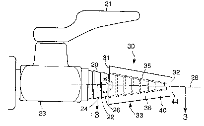
As can best be seen in Figure 1, the gas outlet nozzle 20 is a horizontally disposed
elongated structure having a generally tapered shape ext~nlling outwardly from the gas outlet
base 23. A gas flow control handle 21 is pivotally mounted on the gas outlet base 23 at the
top thereof so as to permit control of the flow of natural (or other) gas. The nozzle 20 has a
plurality of serrations 22 on the exterior thereof, with these serrations 22 having a back face
26 that is generally perpendicular to the longitudinal axis 28 of the nozzle 20, and having a
- 21377~7
-
front face 24 that is angled with respect to the longitudinal axis 28 of the nozzle 22. The
manner in which the serrations 22 are angled makes it easier to connect a rubber hose, such
as a hose leading to a bunsen burner, onto the nozzle 20 and makes it more difficult to
subsequently remove the rubber hose from the nozzle 20.
The cap member 30 has an open first end 31, a generally closed second end 32, and a
peripherally disposed main body portion 33. In the preferred embodiment, the cap member 30
is made from a plastic material such as nylon, or the like, and is formed by way of injection
molding. The manufacturing process per se, however, is not necessarily important, and would
be dictated by m~nllf~cturing and cost considerations.
The main body portion 33 has an inner surface 34 defining a frustum shaped nozzle
receiving recess 35 and an outer surface 36. The first end 31 of the main body portion 33 is
open to provide access to the nozzle receiving recess 35 and the second end 32 of the main
body portion 30 is generally closed to preclude access to the nozzle receiving recess 35.
In the preferred embodiment, the peripherally disposed main body portion 33 comprises
co-operating inner and outer shells 38 and 40, with the inner shell 38 shaped and dimensioned
to fit snugly into the outer shell 40. A guide member 39 extends outwardly from the inner
shell 38 and is received in a recess 41 in the outer shell 40 so as to rotationally align the inner
and outer shell 38 and 40. The inner and outer shells 38, 40 are preferably sonically welded
together, or glued together, so as to securely join them one to the other. The inner shell 38
defines the inner surface 34 of the main body portion 33 and the outer shell 40 defines the
outer surface 36 of the main body portion 33.
The inner shell 38 includes a closed end portion 42, and the outer shell 40 includes a
closed end portion 44, with the two end portions 42, 44 preferably intim~tely contacting each
other in supporting relation. The closed end portion 42 of the inner shell 38 together with the
closed end portion 44 of the outer shell 40, form the generally closed second end 32 of the cap
member 30. The first end portion 42 of the inner shell 38 may be shaped and dimensioned to
receive a resiliently deformable abutment member 46 therein, which abutment member 46 abuts
against the open end of the gas outlet nozzle 20 in sealing relation thereto, so as to preclude
213~707
the escape of gas thelerloll~ in the event that the gas outlet nozzle 20 is turned on while the
cap member 30 is locked in place thereon. In this manner, the cap member 30 of the present
invention also acts as a safety cap by precluding gas from being unwantedly discharged from
the gas outlet nozzle 30.
A spring metal lock member 50 is mounted in operative relation to the main body
portion 33 between the inner shell 38 and the outer shell 40. A shallow indentation 47 is
formed in the outer periphery of the inner shell 38, which indentation 47 is shaped and
dimensioned to received and retain the lock member 50 therein, in trapped interposed relation
between the inner shell 38 and the outer shell 40. The lock member comprises at least one
projecting lock portion 52. In the preferred embodiment, there are two projecting lock portions
52 disposed in serial relation one to the other. Each of the projecting lock portions 52 is
moveable between a first locking position, as can best be seen in Figure 3 and a second
unlocking position as can best be seen in Figure 6.
The two projecting lock portion 52 pass through an opening 48 in the inner shell 38,
and extend into the nozzle receiving recess 35. The lock member 50 is preferably made from
spring metal material, which spring metal material causes the projecting lock portions 52 to be
biased to said first locked position. However, suitable plastics having the requisite stiffness
and memory characteristics could also be employed.
When the cap member 30 is in place on the gas outlet nozzle 20, the projecting lock
portions 52 are each in their first locking position whereat the projecting lock portions 52 each
project into the nozzle receiving recess 35 so as to be in interfering relation with one of the
plurality of back faces 26 of the respective serrations 22 on the exterior of the gas outlet nozzle
20, so as to thereby lock the cap member 30 in place and preclude the cap member 30 from
being removed from the gas outlet nozzle 20.
The cap member 30 further comprises an access passageway 60 in the inner shell 38
of the peripherally disposed main body portion 33. In the preferred embodiment, the access
passageway 60 is formed in the inner shell 36, and comprises a pair of parallel slots 62 in the
inner shell 36, which slots 62 extend inwardly from the inner face 38a of the inner shell 38.
A key member 64 having a pair of flanges 66 and a blade portion 68 disposed between the
flanges 66, is shaped and dimensioned to be removably inserted into the access passageway
21377~7
_v
60 such that the blade portion 68 is interposed between the periphery of the gas outlet nozzle
20 and the flanges 66 are inserted one each into the respective of the slots 62. The slots 62
are, of course, shaped and dimensioned receive the flanges 66 of a co-operating key member
64 therein. The access passageway 60 is thereby shaped and dimensioned to removably receive
5 the co-operating key member 64 therein, so as to permit access by the key member 64 to the
projecting lock portions 52 of the lock member 50. The parallel slots 62 are positioned such
that the projecting lock portions 52 of the lock member 50 are disposed therebetween. When
the key member 64 is inserted into the access passageway 60, the blade portion 68 of the key
member 64 contacts and thereby moves the projecting lock portions 52 from their first locking
10 position to their second unlocking position, thus permitting the cap member 30 to be removed
from the nozzle 20.
Preferably, the key member 64 is made from a metal material but may also be madefrom a plastic material. The spanning or blade portion 68 of the key member should be about
0.020 inches in thickness in order to fit between the inner shell 38 of the main body portion
33 of the cap member 30 and the periphery of the serrations 22 on the gas outlet nozzle 20,
when the cap member 30 is locked in place on the nozzle 20. At the same time, this limited
clearance acts so as to preclude other objects, such as bobby pins, from being insertable
between the gas outlet nozzle 20 and the cap member 30 in an attempt to release the cap
member 30. The flanges 66 of the key member 64 are included so as to give the key member
20 64 extra strength as the extremely thin blade portion 68 may have very little strength itself.
The cap member 30 may also include a retention strap 37 that is adapted to securely
tie the cap member 30 to the gas outlet base 23 and thereby preclude the cap member 30 from
becoming lost.
Other modifications and alterations may be used in the design and manufacture of the
25 mechanical security al~pal~lus of the present invention without departing from the spirit and
scope of the accompanying claims.
b:6 196-1 cp~rifi~ n5~ ^ 1 :mlp:w2 194