Language selection

Search

Patent 2137954 Summary

Third-party information liability

Some of the information on this Web page has been provided by external sources. The Government of Canada is not responsible for the accuracy, reliability or currency of the information supplied by external sources. Users wishing to rely upon this information should consult directly with the source of the information. Content provided by external sources is not subject to official languages, privacy and accessibility requirements.

Claims and Abstract availability

Any discrepancies in the text and image of the Claims and Abstract are due to differing posting times. Text of the Claims and Abstract are posted:

  • At the time the application is open to public inspection;
  • At the time of issue of the patent (grant).
(12) Patent Application: (11) CA 2137954
(54) English Title: RESONANCE ABSORBER
(54) French Title: ABSORBEUR DE RESONANCE
Status: Deemed Abandoned and Beyond the Period of Reinstatement - Pending Response to Notice of Disregarded Communication
Bibliographic Data
(51) International Patent Classification (IPC):
  • E04B 1/84 (2006.01)
  • F16F 15/02 (2006.01)
  • G10K 11/172 (2006.01)
(72) Inventors :
  • ERMERT, KLAUS (Germany)
  • RODER, ARNO (Germany)
  • ZIMMERMANN, KLAUS (Germany)
(73) Owners :
  • LFK-LENKFLUGKOERPERSYSTEME GMBH
(71) Applicants :
  • LFK-LENKFLUGKOERPERSYSTEME GMBH (Germany)
(74) Agent: KIRBY EADES GALE BAKER
(74) Associate agent:
(45) Issued:
(22) Filed Date: 1994-12-13
(41) Open to Public Inspection: 1995-06-17
Examination requested: 2001-11-29
Availability of licence: N/A
Dedicated to the Public: N/A
(25) Language of filing: English

Patent Cooperation Treaty (PCT): No

(30) Application Priority Data:
Application No. Country/Territory Date
P 43 43 008.2 (Germany) 1993-12-16

Abstracts

English Abstract


A resonance absorber for the damping of structure-
borne vibrations has a number of freely swinging slats
with different resonance frequencies. The slats are
arranged on a common base which can be connected with a
body to be damped, and are constructed as double slats
comprising a damping coating which is in each case
squeezed between the two slats elements.


Claims

Note: Claims are shown in the official language in which they were submitted.

WHAT IS CLAIMED IS:
1. Resonance absorber for damping structure-borne
vibrations, of the type comprising a plurality of free-
swinging vibration absorbing elements, each having a
different resonance frequency, said vibration absorbing
elements being arranged on a common base which can be
connected with a body to be damped, wherein each of said
vibration absorbing elements comprises a double slat
structure having at least two slats, with a damping
coating sandwiched between said two slats.
2. Resonance absorber according to Claim 1, wherein
the two slats of each vibration absorbing element are
congruent with each other.
3. Resonance absorber according to Claim 1, wherein
a plurality of double slats are stacked above one another
separated at fixed distances, base surfaces of said
double slats being in contact with one another for
transmitting structure-borne noise vibrations.
4. Resonance absorber according to Claim 2,
wherein a plurality of double slats are stacked above one
another separated at fixed distances, base surfaces of
said double slats being in contact with one another for
transmitting structure-borne noise vibrations.
-9-

5. Resonance absorber according to Claim 3, wherein
the double slats of a stack are congruent but have
different thicknesses.
6. Resonance absorber according to Claim 1, wherein
several double slats of different lengths are arranged
side-by-side on a common base.
7. Resonance absorber according to Claim 5,
wherein several double slats of different lengths are
arranged side-by-side on a common base.
8. Resonance absorber according to of Claim 1,
wherein a layer of double slats of different lengths is
formed by comb-type slats in two congruent rectangular or
square plates at two opposite ends while maintaining a
central base strip extending diagonally over the plate
surface.
9. Resonance absorber according to of Claim 6,
wherein a layer of double slats of different lengths is
formed by comb-type slats in two congruent rectangular or
square plates at two opposite ends while maintaining a
central base strip extending diagonally over the plate
surface.
10. Resonance absorber according to Claim 8,
wherein several layers of double slats with different
-10-

thicknesses and congruent base strips are stacked above
one another, ends of the double slats being free-standing
but the base strips being in contact with one another.
11. Resonance absorber according to Claim 1,
wherein the damping layer within a stack of double slats
differs from layer to layer.
12. Resonance absorber according to Claim 10,
wherein the damping layer within a stack of double slats
differs from layer to layer.
13. Resonance absorber according to Claim 1,
wherein the lengths of the double slats are graduated
according to the following equation:
<IMG>
wherein
ln = length of the nth slat
lo = length of the longest slat
n = course index between 0 and N-1
N = total number of different slats
f1 = first resonance frequency of the longest slat
f2 = second resonance frequency of the longest slat.
-11-

14. Resonance absorber according to Claim 3,
wherein the lengths of the double slats are graduated
according to the following equation:
<IMG>
wherein
ln = length of the nth slat
lo = length of the longest slat
n = course index between 0 and N-1
N = total number of different slats
f1 = first resonance frequency of the longest slat
f2 = second resonance frequency of the longest slat.
15. Resonance absorber according to Claim 8,
wherein the lengths of the double slats are graduated
according to the following equation:
<IMG>
wherein
ln = length of the nth slat
lo = length of the longest slat
-12-

n = course index between 0 and N-1
N = total number of different slats
f1 = first resonance frequency of the longest slat
f2 = second resonance frequency of the longest slat.
16. Resonance absorber according to Claim 11,
wherein the lengths of the double slats are graduated
according to the following equation:
<IMG>
wherein
ln = length of the nth slat
lo = length of the longest slat
n = course index between 0 and N-1
N = total number of different slats
f1 = first resonance frequency of the longest slat
f2 = second resonance frequency of the longest slat.
-13-

Description

Note: Descriptions are shown in the official language in which they were submitted.


~_ ~137954
RESON:~NCE ABSORBER
BACl~GRO~JND AND SI~RY OF THE INVENTION
This inyention relates to a device for damping
structure-borne noise vibrations, comprising a number of
free-swinging vibration absorbing elements in the form of
slats, with different resonance frequencies. The slats
are arranged on a com~on base which can be connected with
a body to be damped.
Vibration absorbers of the above-mentioned type are
known, for example, from German Patent Document DE 1 071
364 or German Patent Document DE-OS 2 163 798. In the
case of these vibration absorbers, the resonance
frequency of the individual slats is coordinated with the
vibrations of the body to be damped. The slats, which
are excited in this manner to carry out resonance
vibrations, therefore absorb vibration energy from the
body to be damped which, by an appropriate damping of the
slats, will finally be converted to heat.
To increase the vibration-damping effect, it is
known from European Patent Application EP 0 Q20 2~ B1 to
stack plate-shaped slats above one another, with layers
of a damping material being arranged between the slats.
The individual slats and the damping materia~ are
coordinated with one another so that the individual
plates vibrate against one another and in the process

213795~
compress and relax the damping material. In such a
resonance vibration absorber, the intermediate layers
made of damping material must be relatively thick and
soft, in order to avoid excessive coupling between the
individual slats, which would change the whole vibration
behavior.
It is an object of the present invention to provide
a vibration absorber of the above-mentioned type which,
while-the effect is the same, permits a more compact
construction, can be coordinated with a frequency range
which is as wide as possible, and requires smaller
amounts of damping material than previously.
This ob3ect is achieved by the vibration absorber
according to the invention which on the one hand has
freely swinging slats that are constructed as double
slats but are not vibrationally coupled to adjacent
double slats and therefore exhibit a defined vibration
behavior. On the other hand, to increase the damping of
one double slat respectively, a known technology referred
to as a "squeezed coating" is used for the d~mping of
bending vibrations of thin metal sheets. In this case,
the damping layer is deformed by shearing rGther than by
compressing or relaxing, so that the damping layers may
be extremely thin.

21379~
The slats may be arranged either side-by-side in a
layer, as ,for example, according to German Patent
Document DE 2 163 798, or sandwiched above one another,
as, for example, corresponding to German Patent Document
S DE 1 071 364 or European Patent Document EP 0 020 284 B1.
In a particularly compact arrangement, several layers
having a congruent outer circumference are stacked abcve
one another SG that a block of freely swinging double
slats is created, which are arranged in a linear and
column--shaped manner.
Other objects, advantages and novel features of the
present invention will become apparent from the following
detailed description of the invention when considered in
conjunction with the accompanying drawings.
BRIEF DESCRIPTION OF THE DRAWING
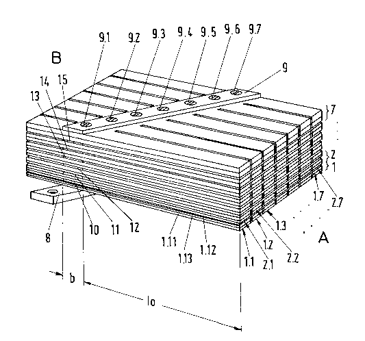
The single Figure is a partially schematic depiction
of the vibration absorbing element according to the
invention.
DETAILED DESCRIPTION OF THE DRAWING
The resonance absorber illustrated in the figure
comprises seven layers (1 to 7) of double slats 1.1, 1.2,
1.3 ..., each layer being made of two congruent metal
plates of the same thickness. On two opposite sides A

2137~5~
and B, the plates are notched in the manner of a comb. A base
strip 8 of a width b extends diagonally over the plate
surface, and remains unnotched. Congruently extending spacer
pieces 10 to 15 inserted between the individual layers
parallel to the base strip acoustically couple the individual
plates in the area of the base strip 8. The layers and the
spacer pieces are held together by means of the base strip 8
and a so-called adapter plate 9 by means of tightening screws
9.1 to 9.7. Particularly in mass production of the absorbers,
the spacer pieces may also be integrated directly with the
plates, for example, by means of corresponding casting molds
for the plates or by a stamping or milling of flat plates. By
way of the base plate 8, the resonance absorber is connected
with a body to be damped in a force and moment-locking manner.
Before stacking and cutting, a damping layer for instance
type E3512 A and B from Company Permabond is applied between
the two plates of a layer (1 to 7) so that a sandwich-type
structure is created. After the cutting of the plates, double
slats 1.1, 1.2, ... 1.7 are created in this manner, each
comprising two metallic slat elements, for example, 1.11 and
1.12, with a coating, such as 1.13, which is sandwiched
between them.
If, as in the illustrated embodiment, the base strip 8
extends asymmetrically over the plane of the plate, a
plurality (2 x 7) of double slats are created, each

213795~
having a different length and therefore a different
resonance frequency.
If, as also shown in the embodiment, the layer
thickness of the individual plate elements increases from -
layer to layer (from 1 to 7), the number of slats with
different resonance frequencies is multiplied by the
number of iayers.
The following equation may be used to calculate the
resonance frequenciés of the double slats having a
constant cross-sectional course:
S 2
2~12~ A-p
wherein
sn : natural frequency factor
1 : length of slat
I : geometrical moment of inertia
A : cross-sectional surface of slat
E : modulus of elasticity
p : density
The natural frequency factors depend on the manner
of the clamping of the slats and on the ordinal of the
natural vibration. In "Technische Akustik" ("Technical

2137954
`_
Acoustics") by IVAR VEIT, Publishers: Vogel Fachbuch, 4th
Edition, 1988, the following factors are indicated for
the fundamental oscillation and the first 4 harmonic
oscillations for a rod which is clamped in on one side
S and which may be considered to be the equlvalent of the
absorber slat according to the invention:
s~ 875 (fundamental oscillation)
s2 = 4.694 (lst harmonic oscillation)
S3 = 7,8SS (2nd harmonic oscillation)
0 S4 =10~ 996 (3rd harmonic oscillation)
S5 =14,137 (4th harmonic oscillation)
By the connecting of two slat elements to form a
double slat with an intermediate damping layer, a
coupling factor must be taken into account with respect
to the determination of the resonance frequency of such a
double slat. Thus, the following will apply:
fnD = K-fn -
wherein
fnD : natural frequency of the do~ble slat
K : coupling factor.
According to the material, the coupling factor
ranges between the values of 1 anà 2. In the case of a
--6--

2137954
.
very soft damping mass, the natural frequency of the
double slat will increase only insignificantly; in the
case of a very hard damping mass, the coupling factor of
almost 2, thus a frequency doubling, is obtained.
A gradation of the slats according to the following
rule is particularly advantageous:
( f2 )
wherein
ln = length of the nth slat
lo = length of the longest slat
n = course index between 0 and N-1
N = total number of different slat lengths
fl = first resonance frequency of the longest slat
f2 = second resonance frequency of the longest slat.
The provides the double slats with different damping
layers results in an expansion of the temperature range
for the vibration absorber.
Although the invention has been described and
illustrated in detail, it is to be clearly understood
that the same is by way of illustration and example, and
is not to be taken by way of limita_ion. The spirit and

2137954
scope of the present invention are to be limited only by
the terms of the appended claims.
-8-

Representative Drawing
A single figure which represents the drawing illustrating the invention.
Administrative Status

2024-08-01:As part of the Next Generation Patents (NGP) transition, the Canadian Patents Database (CPD) now contains a more detailed Event History, which replicates the Event Log of our new back-office solution.

Please note that "Inactive:" events refers to events no longer in use in our new back-office solution.

For a clearer understanding of the status of the application/patent presented on this page, the site Disclaimer , as well as the definitions for Patent , Event History , Maintenance Fee  and Payment History  should be consulted.

Event History

Description Date
Inactive: IPC from MCD 2006-03-11
Application Not Reinstated by Deadline 2004-12-13
Time Limit for Reversal Expired 2004-12-13
Deemed Abandoned - Failure to Respond to Maintenance Fee Notice 2003-12-15
Inactive: Application prosecuted on TS as of Log entry date 2002-01-22
Letter Sent 2002-01-22
Inactive: Status info is complete as of Log entry date 2002-01-22
Request for Examination Requirements Determined Compliant 2001-11-29
All Requirements for Examination Determined Compliant 2001-11-29
Letter Sent 2000-12-28
Reinstatement Requirements Deemed Compliant for All Abandonment Reasons 2000-12-13
Letter Sent 2000-02-22
Deemed Abandoned - Failure to Respond to Maintenance Fee Notice 1999-12-13
Inactive: Multiple transfers 1999-09-21
Application Published (Open to Public Inspection) 1995-06-17

Abandonment History

Abandonment Date Reason Reinstatement Date
2003-12-15
1999-12-13

Maintenance Fee

The last payment was received on 2002-11-27

Note : If the full payment has not been received on or before the date indicated, a further fee may be required which may be one of the following

  • the reinstatement fee;
  • the late payment fee; or
  • additional fee to reverse deemed expiry.

Please refer to the CIPO Patent Fees web page to see all current fee amounts.

Fee History

Fee Type Anniversary Year Due Date Paid Date
Registration of a document 1995-12-13
MF (application, 3rd anniv.) - standard 03 1997-12-15 1997-11-25
MF (application, 4th anniv.) - standard 04 1998-12-14 1998-11-19
Registration of a document 1999-09-21
MF (application, 6th anniv.) - standard 06 2000-12-13 2000-12-13
Reinstatement 2000-12-13
MF (application, 5th anniv.) - standard 05 1999-12-13 2000-12-13
MF (application, 7th anniv.) - standard 07 2001-12-13 2001-11-26
Request for examination - standard 2001-11-29
MF (application, 8th anniv.) - standard 08 2002-12-13 2002-11-27
Owners on Record

Note: Records showing the ownership history in alphabetical order.

Current Owners on Record
LFK-LENKFLUGKOERPERSYSTEME GMBH
Past Owners on Record
ARNO RODER
KLAUS ERMERT
KLAUS ZIMMERMANN
Past Owners that do not appear in the "Owners on Record" listing will appear in other documentation within the application.
Documents

To view selected files, please enter reCAPTCHA code :


To view images, click a link in the Document Description column. To download the documents, select one or more checkboxes in the first column and then click the "Download Selected in PDF format (Zip Archive)" or the "Download Selected as Single PDF" button.

List of published and non-published patent-specific documents on the CPD .

If you have any difficulty accessing content, you can call the Client Service Centre at 1-866-997-1936 or send them an e-mail at CIPO Client Service Centre.


Document
Description 
Date
(yyyy-mm-dd) 
Number of pages   Size of Image (KB) 
Representative drawing 1998-03-09 1 43
Description 1995-06-17 8 210
Claims 1995-06-17 5 115
Cover Page 1995-11-06 1 17
Abstract 1995-06-17 1 12
Drawings 1995-06-17 1 44
Courtesy - Abandonment Letter (Maintenance Fee) 2000-01-10 1 185
Notice of Reinstatement 2000-12-28 1 171
Reminder - Request for Examination 2001-08-14 1 129
Acknowledgement of Request for Examination 2002-01-22 1 178
Courtesy - Abandonment Letter (Maintenance Fee) 2004-02-09 1 176
Fees 2000-12-13 1 61
Fees 1996-11-20 1 79