Note: Descriptions are shown in the official language in which they were submitted.
-~137973
'_
GASTROI~.lr~lINAL NEEDLE MECHANISM
BACKGROUND OF THE INVENTION
The present invention relates to an adjustable needle
mechanism finding particular use in combination with an
endoscope.
Endoscopes are used with injection needles to inject
gastrointestinal mucosa with liquid reagents to achieve
desired effects. For example, sclerosants may be injected
for esophageal varices and epinephrine may be injected to
control bleeding. In order to accomplish such treatment, a
needle mounted on the end of a long tube may be passed
through a channel of the endoscope to inject the desired
objective. The needle is shielded by a catheter within which
the needle and tube are received. When the endoscope is
properly located at the injection site, the needle is
projected from the end of the catheter and the injection is
effected.
It has been found that the length of the catheter and the
tube can be affected between the time of manufacture of the
mechanism and the time of use in the endoscope. For example,
when the mechanism is sterilized the catheter may be
lengthened or shortened or the tube may be lengthened or
shortened resulting in the mechanism not projecting the
needle sufficiently for proper injection of reagent. Such a
problem may require the use of the mechanism to trim back the
catheter before use.
Thus, the time of hospital personnel is not used
effectively and damage to the mechanism may result.
It is an object of the present invention to provide
improved gastrointestinal needle mechanism. A further
objective is to provide a needle mechanism which eliminates
the need for trimming t~le catheter.
_ ~37~7~
--2--
SUMMARY OF THE INVENTION
One embodlment of the present lnventlon mlght
lnvolve an ad~ustable needle mechanism lncludlng a catheter.
There ls provlded a tube slldable wlthln the catheter and a
head secured to one end of the catheter. A hollow needle ls
mounted on one end of the tube ln communlcatlon wlth the tube.
The tube ls slldable ln the catheter to a flrst posltlon
whereln the needle pro~ects out of the other end of the
catheter and ls slldable in the catheter to a second posltlon
where ln the needle is wlthdrawn lnto the catheter. There ls
also provlded a handle flxed to the tube and extendlng through
the head. The handle has a port communlcatlng wlth the tube.
A handle stop member ls ad~ustably mounted on the head ln the
path of the handle. The handle ls movable to move the needle
to the flrst positlon whereln the handle engages the handle
stop member. The handle stop member ls ad~ustable on the head
to change the dlstance that the needle pro~ects out of the
catheter when the needle ls ln the flrst posltlon.
In accordance wlth the present lnventlon, there ls
provlded an ad~ustable needle mechanlsm comprlslng
a catheter;
a first tube slldable wlthln sald catheter;
a head secured to one end of sald catheter;
a hollow needle mounted on one end of sald tube ln
communlcatlon wlth sald tube, sald tube belng slldable ln sald
catheter to a flrst posltlon whereln sald needle pro~ects out
of the other end of sald catheter and slldable in sald
~A~ 6
1211-1155
~ ~1 3~73
_
-2a-
catheter to a second positlon whereln sald needle ls withdrawn
lnto said catheter;
a handle fixed to said tube, said handle havlng a port
communicatlng wlth said tube;
a handle stop member threadedly mounted on said head ln
the path of sald handle, sald handle belng movable to move
said needle to sald first posltlon wherein sald handle engages
sald handle stop member, sald handle stop member belng
adjustable by screwlng said stop member lnto or out of sald
head to change the dlstance that sald needle pro~ects out of
sald catheter when sald needle ls ln said first position.
61211-1155
~,
-2137973
_.
BRIEF DESCRIPTION OF THE DRAWINGS
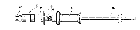
Fig. 1 is a side elevation of an adjustable needle
mechanism embodying the present invention.
Fig. 2 is a view similar to Fig. 1 showing the needle
projected from the catheter of the adjustable needle
mechanism of Fig. 1.
Fig. 3 is a view sirnilar to Fig. 2 showing the needle
projected a greater distance from the end of the catheter.
Fig. ~ is a longitudinal sectional view of the adjustable
needle mechanism.
-2137973
DESCRIPTION OF THE PREFERRED EMBODIMENT
For the purposes of promoting an understanding of the
principles of the invention, reference will now be made to
the embodiment illustrated in the drawings and specific
language will be used to describe the same. It will
nevertheless be understood that no limitation of the scope of
the invention is thereby intended, such alterations and
further modifications in the illustrated device, and such
further applications of the p~inciples of the invention as
illustrated therein being contemplated as would normally
occur to one skilled in the art to which the invention
relates.
Referring to the figures, a catheter or sheath 10
composed of clear plastic has slidably received therein a
white plastic tube 11. The tube 11 has a hollow metal needle
12 mounted on its end so that the hollow interior 15 of the
needle is in communication with the hollow interior 16 of the
tube 11. A head 17 is fixed to one end of the catheter 10 by
means of a metal stop member or element 20 which extends into
the head 17 and also into the catheter 10 and may have
suitable adhesive thereon fixing it to both the head 17 an~
the catheter 10.
A handle 21 includes a luer lock fitting 22 and a metal
tube 25 which is fixed to the white plastic tube 11. As
shown in Fig. 1 and Fig. 2 the tube 11 is movable between a
first position wherein the needle projects out of the end 26
of the catheter and a second position shown in Fig. 1 wherein
the needle is received within the catheter. Fig. 4 shows the
tube (and needle) intermediate these two positions. The
movement of the needle 12 between the positions of Fig. 1 and
Fig. 2 can be accomplished by moving the handle 21 relative
to the head 17. Thus when the handle 21 is pulled away from
the head 17 the position of Fig. 1 is achieved while pushing
of the handle 21 toward the head 17 produces the position of
- -2137973
_
--5--
Fig. 2.
A stop member 30 is adjustably mounted on the head 17 in
the path of the handle 21. The stop member 30 is threadedly
mounted on the head 17 by means of threads 31. As shown in
Figs. 2 and 3 the position of the stop member 30 can be
adjusted by screwing it into the head 17 as shown in Fig. 3
or by unscrewing it from the head 17 as shown in Fig. 2 In
Figs. 2 and 3 the handle 21 is moved against the adjustable
stop 30. It can be seen in Fig. 2 that the needle 12 does
not project out of the catheter 10 to the same degree that it
projects out of the catheter 10 in Fig. 3. Thus the amount
of projection of the needle can be controlled and set by
adjusting the position of the stop member 30.
A metal collar 35 is fixed to the tube 25 and is located
contiguous to the end of the white plastic tube 11. When the
handle 21 is pulled as far as possible away from the head 17
to the position shown in Fig. 1 the metal collar 35 engages
the metal stop 20 thus preventing further movement of the
handle 21 away from the head and stop member 30.
II1 order to use the adjustable needle mechanism with an
endoscope the needle is first withdrawn into the outer sheath
or catheter 10 by fully retracting the handle 21, that is
pulling it away from the head 17. A prefilled syringe is
then attached to the luer lock fitting 22. The needle
25 extension is determined by advancing the handle fully forward
against the stop 30. In one embodiment of the invention it
has been determined that the needle 12 should extend 5 mm
from the end 26 of the catheter. If the needle does not
extend the appropriate desired distance from the catheter 26,
the knob 40 of the stop member 30 is rotated to cause the
stop member 30 to move rightwardly as viewed in the Figs. so
as to permit a greater amount of extension of the needle. If
on the other hand the needle initially projects too great a
distance the knob 40 can be rotated to move the stop member
away from the head 17 so as to properly set the projected
position of the needle.
-2137973
--6--
The needle is then retracted into the sheath or catheter
26 by pulling the handle 21 to the position of Fig. 1. The
adjustable needle mechanism is then introduced into the
accessory channel of the endoscope using short movement
s increments. The needle should be kept retracted when the
sheath is being advanced through the endoscope to protect the
endoscope from damage. Once the mechanism is visualized int
he endoscopic field of view, advancement is stopped and the
target site is selected. With the sheath in endoscopic view,
lo the needle is projected from the sheath. If the needle
e~tension does not appear to be adequate, fine adjustment can
be obtained by rotating the adjustment knob 40. Tlle extended
needle may then be inserted into the targeted tissue site and
the injection completed. The needle catheter should be
withdrawn from the target site into the sheath by pulling
back on the handle 21 relative to the head 17 before
retracting the catheter sheath through the endoscope
accessory channel in order to protect the endoscope from
damage.
In representative embodiments of the invention the
catheter or sheath 10 had a length of 200 and 240 cm. and an
O.D. of approximately 2.3 mm otherwise known as 7 French.
the inner tube 11 has a 4 French size or, in other words, an
approximate 1.35 mm O.D. The needle 12 is either a 23 or 25
gauge needle and has a crimped section 45 of cannula securing
it to the end of the tube 11. The cannula 45 is shown with a
slightly larger O.D. than actual in order to make it visible
in Fig. 4. It should be understood, however, that the O.D.
is sufficiently small to allow it to slide easily in the
catheter 10.
It can be appreciated that the mechanism of this
invention provides an improved needle mechanism which
eliminates the necessity of trimming the end of the
catheter. It will also be evident that the present device
provides the additional advantage of allowing adjustment of
2137973
--7--
the amount of projection of the needle from the sheath when
the mechanism is in use and is projecting from the
endoscope..
While the invention has been illustrated and described in
detail in the drawings and foregoing description, the same is
to be considered as illustrative and not restrictive in
character, it being understood that only the preferred
embodiment has been shown and described and that all changes
and modifications that come within the spirit of the
invention are desired to be protected.