Language selection

Search

Patent 2138142 Summary

Third-party information liability

Some of the information on this Web page has been provided by external sources. The Government of Canada is not responsible for the accuracy, reliability or currency of the information supplied by external sources. Users wishing to rely upon this information should consult directly with the source of the information. Content provided by external sources is not subject to official languages, privacy and accessibility requirements.

Claims and Abstract availability

Any discrepancies in the text and image of the Claims and Abstract are due to differing posting times. Text of the Claims and Abstract are posted:

  • At the time the application is open to public inspection;
  • At the time of issue of the patent (grant).
(12) Patent Application: (11) CA 2138142
(54) English Title: INNER CANNULA FOR TRACHEOSTOMY TUBE
(54) French Title: CANULE INTERNE POUR TUBE DE TRACHEOTOMIE
Status: Deemed Abandoned and Beyond the Period of Reinstatement - Pending Response to Notice of Disregarded Communication
Bibliographic Data
(51) International Patent Classification (IPC):
  • A61M 16/04 (2006.01)
(72) Inventors :
  • MAHONEY, MICHAEL R. (United States of America)
  • HORTON, DUANE L. (United States of America)
  • BENWAY, CHERYL A. (United States of America)
(73) Owners :
  • MALLINCKRODT INC.
(71) Applicants :
  • MALLINCKRODT INC. (United States of America)
(74) Agent: OSLER, HOSKIN & HARCOURT LLP
(74) Associate agent:
(45) Issued:
(86) PCT Filing Date: 1993-06-24
(87) Open to Public Inspection: 1994-01-20
Examination requested: 2000-02-02
Availability of licence: N/A
Dedicated to the Public: N/A
(25) Language of filing: English

Patent Cooperation Treaty (PCT): Yes
(86) PCT Filing Number: PCT/US1993/006046
(87) International Publication Number: US1993006046
(85) National Entry: 1994-12-14

(30) Application Priority Data:
Application No. Country/Territory Date
07/907,385 (United States of America) 1992-07-01

Abstracts

English Abstract


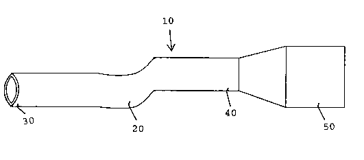
The present invention relates to a new, superior inner cannula (10) for insertion into a tracheostomy tube. The inner cannu-
la according to the present invention is formed of a material that allows the inner cannula to have a smooth lumen, while avoid-
ing kinking or collapse when inserted into the tracheostomy tube.


Claims

Note: Claims are shown in the official language in which they were submitted.


What is claimed is:
1 An inner cannula for insertion into a tracheostomy
tube, said inner cannula comprises a flexible tube
having a smooth lumen.
2 An inner cannula according to claim 1, wherein said
flexible tube is formed of a flexible material
having sufficient strength to avoid kinking and
collapse when inserted into a tracheostomy tube.
3 An inner cannula according to claim 2, wherein said
flexible material is a expanded polytetrafluoro-
ethylene material or other material having a similar
polymer matrix.
4 An inner cannula for inserting into a tracheostomy
tube, wherein said inner cannula comprises a
flexible tube having a wall thickness of 0.3mm to
0.5mm.
An inner cannula according to claim 4, wherein said
wall thickness is about 0.4mm.

Description

Note: Descriptions are shown in the official language in which they were submitted.


WO94/011~6 213 81~ ~ PCT/US93/06~6
Inner Cannula For TracheostomY Tube
Backqround
Tracheostomy tubes are normally inserted into the
trachea of a patient through an opening cut in the front of
the throat. The tracheostomy tube is generally designed to
include a relatively straight proximal and distal end
portion connected by a curved central portion.
Alternatively, the tracheostomy tube may be formed entirely
in an arced configuration.
The distal end portion of the tracheostomy tube
extends down into the trachea, while the proximal end
portion extends through the cut in the throat. An
inflatable cuff may be included around the distal end
portion and may be used to seal the space between the tube
and the surrounding wall of the trachea, so that all
ventilation cccurs through the tracheostomy tube.
During use, mucous and other secretions collect and
dry within the tracheostomy tube causing obstruction of the
ventilation path. Therefore, it is necessary to
periodically remove the tracheostomy tube for cleaning,
followed by reinsertion into the patient's trachea. This
removal and reinsertion is traumatic to the patient, and
increases the risk of injury to the trachea and surrounding
membranes. In addition, a skilled practitioner is required
to administer the procedure.
To overcome the disadvantages of removal and
reinsertion, it has been proposed to include a second,
removable, tube or cannula which can be inserted into the
tracheostomy tube. This inner cannula may easily be
removed from the tracheostomy tube and cleaned or replaced
by a new inner cannula, without disturbing the tracheostomy
tube. The inner cannula must be flexible enough to be

wos4/olls6 PCT/US93/06~6
2~381 ~ 2
inserted into the proximal end of the tracheostomy tube and
then pushed around the curved central portion into the
distal end. However, the inner cannula must also be rigid
enough to avoid collapse or kinking in the curved portion,
which would restrict or close off the ventilation pathway.
One type of inner cannula is described in US Patent
3,443,564 to Oehmig, and includes a spirally wound wire
along a portion of its length which will correspond to the
curved portion of a tracheostomy tube when inserted. This
inner cannula has several disadvantages including the lack
of a solid wall where the wound wire exists. This is
disadvantageous because gaps will be present between
convolutions of the wire, which will gather mucous and
other secretions. Also, such an inner cannula is
relatively expensive, so as not to be suitable as a
disposable unit. Therefore, this inner cannula must be
cleaned every time it is removed, which is a difficult task
because of the wire and grooves formed there between.
Another known inner cannula is shown in US Patent
3,948,274 to Zeldman et al, such inner cannula comprising
a normally straight one-piece flexible tube of plastic
having circumfirentially formed corrugations along a
portion of its length. The corrugations enable the inner
cannula to have enough flexibility to be pushed through the
curved portion of a tracheostomy tube while maintaining
structural integrity and preventing collapse of the inner
cannula when inserted. However this inner cannula also has
disadvantages associated with the corrugations. In
particular, the corrugations will allow relatively rapid
buildup of mucous and other secretions. This buildup
creates a need for relatively frequent removal of the inner
cannula for cleaning or replacement. While this inner
cannula is low in cost, cleaning may still be preferred to

WO94/011~6 2 1 3 8 1 4 2 PCT/US93/06046
replacement, by some patients. Cleaning is made difficult
because the mucous and other secretions may become embedded
- in the corrugations. This in turn may lead to excessive
build up and possible infection.
Therefore, there remains a need in the art for an
inner cannula which overcomes all of the above problems.
Obiects Of The Invention
It is one object of the present invention to provide
a superior inner cannula for use in tracheostomy tubes.
It is another object of the present invention to
provide a flexible inner cannula having a smooth lumen and
which possesses sufficient strength to avoid kinking and
-collapse.
SummarY Of The Invention
The objects above and others are accomplished
according to the present invention, by providing an inner
cannula made from a material which allows for a minimum
outside diameter (OD) to inside diameter (ID) ratio, while
maintaining structural integrity. In particular, the
objects of the present invention are accomplished by
providing an inner cannula formed from a expanded
polytetrafluoroethylene (EPTFE) material or other compound
of similar polymer matrix.
Brief DescriPtion Of The Drawinqs
Fig. l is a plan view of an inner cannula for a

WO94/011~6 PCT/US93/06046
2l38l42
tracheostomy tube according to the present invention.
Detailed Description Of The Invention
Fig. l shows an inner cannula, generally designated by
reference numeral l0, according to the present invention.
The inner cannula l0, comprises a flexible tube 20, having
a distal end 30, and a proximal end 40. The flexible tube
20, has a single lumen extending the entire length thereof.
An end piece 50, is attached to the proximal end 40. The
end piece 50, is formed so as to fit securely into the
distal end of a tracheostomy tube when inserted.
The flexible tube 20, is formed of a material which
has sufficient flexibility to allow for insertion into the
lumen of a tracheostomy tube while maintaining structural
integrity and avoiding kinking and collapse. In
particular, the flexible tube 20, is formed of a material
as described above which also allows the flexible tube 20,
to have a smooth lumen. In a preferred embodiment, the
flexible tube 20, is formed of a EPTFE material or
another compound of similar polymer matrix.
The end piece 50, may be attached to the proximal end
40, by any suitable means, such as adhesive bonding,
compression fitting or an insert molding process.
An inner cannula according to the present invention
provides several advantages over those known in the prior
art. In particular, the use of a material as described
above for the flexible tube of the inner cannula provides
a low ratio of OD to ID. In other words, the walls of the
inner cannula can be very thin, e.g. about 0.4mm thick. In
a particular example, the wall thickness of an inner
cannula for a 9mm tracheostomy tube is from about 0.3mm to

WO94/011~6 2 1~ 8 1 4 2 PCT/US93/06046
0.5mm.
The inner cannula according to the present invention
may have any suitable OD, so as to fit snugly and securely
within any standard tracheostomy tube. In addition, the
inner cannula can be of any suitable length to correspond
with the length of the tracheostomy tube in which it is to
be inserted.
The use of the material described above for the inner
cannula according to the present invention provides several
other advantages. In particular, less drag is exerted on
the tracheostomy tube during insertion of the inner lumen.
Also, there may be less drag exerted on instruments which
may be inserted through the inner cannula and used for
suctioning of the airway of the patient by an attending
practitioner. In addition, there is less resistance to
airflow when the inner cannula is inserted. This is
attributable both the relatively low friction coefficient
of the material used, and because the OD to ID ratio can be
minimized making the ID as large as possible.
Because the inner cannula according to the present
invention can be formed with a smooth lumen, other
advantages are realized over prior art devices. In
particular, it is believed that less build-up of mucous and
other secretions may occur. Therefore, it may not be
necessary to remove and clean or replace the inner cannula
as frequently as needed by prior art devices. The
relatively low cost of the inner cannula according to the
present invention makes replacement highly feasible and
affordable. However, cleaning of the inner cannula
according to the present invention is also possible. The
smooth lumen and low friction coefficient make cleaning
easier and more efficient. There are no corrugations or

WO94/011~6 PCT/US93/06046
2 i38 i 42 6
wires for mucous and secretions to become embedded in.
Therefore, cleaning is more thorough and creates less risk
of subsequent contamination and infection.
The foregoing has been a description of certain
preferred embodiments of the present invention, but is not
intended to limit the invention in any way. Rather, many
modifications, variations and changes in details may be
made within the scope of the present invention.

Representative Drawing
A single figure which represents the drawing illustrating the invention.
Administrative Status

2024-08-01:As part of the Next Generation Patents (NGP) transition, the Canadian Patents Database (CPD) now contains a more detailed Event History, which replicates the Event Log of our new back-office solution.

Please note that "Inactive:" events refers to events no longer in use in our new back-office solution.

For a clearer understanding of the status of the application/patent presented on this page, the site Disclaimer , as well as the definitions for Patent , Event History , Maintenance Fee  and Payment History  should be consulted.

Event History

Description Date
Application Not Reinstated by Deadline 2002-06-25
Time Limit for Reversal Expired 2002-06-25
Deemed Abandoned - Failure to Respond to Maintenance Fee Notice 2001-06-26
Inactive: Application prosecuted on TS as of Log entry date 2000-02-15
Inactive: Status info is complete as of Log entry date 2000-02-15
Letter Sent 2000-02-15
All Requirements for Examination Determined Compliant 2000-02-02
Request for Examination Requirements Determined Compliant 2000-02-02
Inactive: Multiple transfers 1999-01-19
Inactive: Delete abandonment 1997-09-17
Deemed Abandoned - Failure to Respond to Maintenance Fee Notice 1997-06-24
Application Published (Open to Public Inspection) 1994-01-20

Abandonment History

Abandonment Date Reason Reinstatement Date
2001-06-26
1997-06-24

Maintenance Fee

The last payment was received on 2000-04-19

Note : If the full payment has not been received on or before the date indicated, a further fee may be required which may be one of the following

  • the reinstatement fee;
  • the late payment fee; or
  • additional fee to reverse deemed expiry.

Patent fees are adjusted on the 1st of January every year. The amounts above are the current amounts if received by December 31 of the current year.
Please refer to the CIPO Patent Fees web page to see all current fee amounts.

Fee History

Fee Type Anniversary Year Due Date Paid Date
MF (application, 5th anniv.) - standard 05 1998-06-25 1998-06-23
Registration of a document 1999-01-19
MF (application, 6th anniv.) - standard 06 1999-06-24 1999-06-08
Request for examination - standard 2000-02-02
MF (application, 7th anniv.) - standard 07 2000-06-26 2000-04-19
Owners on Record

Note: Records showing the ownership history in alphabetical order.

Current Owners on Record
MALLINCKRODT INC.
Past Owners on Record
CHERYL A. BENWAY
DUANE L. HORTON
MICHAEL R. MAHONEY
Past Owners that do not appear in the "Owners on Record" listing will appear in other documentation within the application.
Documents

To view selected files, please enter reCAPTCHA code :


To view images, click a link in the Document Description column. To download the documents, select one or more checkboxes in the first column and then click the "Download Selected in PDF format (Zip Archive)" or the "Download Selected as Single PDF" button.

List of published and non-published patent-specific documents on the CPD .

If you have any difficulty accessing content, you can call the Client Service Centre at 1-866-997-1936 or send them an e-mail at CIPO Client Service Centre.


Document
Description 
Date
(yyyy-mm-dd) 
Number of pages   Size of Image (KB) 
Abstract 1994-01-19 1 35
Description 1994-01-19 6 227
Claims 1994-01-19 1 21
Drawings 1994-01-19 1 7
Representative drawing 1998-07-27 1 3
Acknowledgement of Request for Examination 2000-02-14 1 180
Courtesy - Abandonment Letter (Maintenance Fee) 2001-07-23 1 182
Fees 2000-04-18 1 44
Fees 1998-06-22 1 39
PCT 1994-12-13 6 235
Fees 1997-06-24 1 41
Fees 1999-06-07 1 32
Fees 1996-06-03 1 32
Fees 1995-06-06 1 37