Note: Descriptions are shown in the official language in which they were submitted.
2138400 ~mA~ ~ ~ ~ n ~ ? ~ ~
R~CrI~rEI~ 2 ~ J h L 1993
1
ADJUSTABLE GRIPPING DEVICE
Technical Fie7.d
THIN INVEEdTION relates to an adjustable gripping
device which in a particular aspect is in the form of an
adjustable socket.
Background Art_
Socket sei~s are a common tool used for driving
bolts and nuts. Usually such sockets sets comprise a
plurality of sockets of different sizes to suit different
sized nuts or bolts. Use of such sockets is often
inconvenient ~~rhere for example many different size nuts or
bolts are encountered as different sockets are required to
be individually detached from the driving tool or wrench
and the correct sized socket reattached to suit the
particular size nut or bolt to be driven. Inconvenience
also often- arises if a particular size socket is not
readily available.
Som~s adjustable sockets have been proposed in the
past to overcome the above problem, however, the known
adjustable have a number of disadvantages. For example
such adjustable sockets are generally relatively complex
with some involving springs to bias gripping jaws
outwardly. The use of springs often causes difficulties in
manufacture and u~~e. Other adjustable sockets such as
those discloaed,in International Patent Application No.
PCT/AU86/01319 have jaws with a limited range of opening so
that their application is limited. Additionally most
adjustable sockets have dimensions which make them
unsuitable for use in confined spaces.
Disclosure of the I:nventivn
The: present invention aims to overcome or at
least alleviate one or more of the above disadvantages by
providing an adjust:ab7_e gripping device which may be in the
form of an adjustable socket which is of simple
construction such as to lend itself to easy manufacture.
The present invention in a preferred form aims to provide
an adjustable gripping device which may be constructed so
as to have ze7_ativ~e7_y small overall dimensions whereby to
SUBSTITUTE SHEET
2~3s4ao p~JA~ ~ ~ ~ ~ ~ ? ~ s
~~cF!vEa
2
enable it to be used in confined spaces. The present
invention further preferably aims to provide an adjustable
gripping device in. which the range of jaw openings is
relatively large so as to facilitate gripping of members of
a range of different sizes. Other objects and advantages
' of the invention will become apparent from the following
description.
With the above and other objects in view the
present invention provides in a first aspect an adjustable
gripping device including a body adapted to be driven for
rotation about a cE~ntral axis, a plurality of jaws spaced
about said central axis and supported for movement relative
to said body and adjuster means mounted to said body and
rotatable relative thereto about said central axis, said
adjuster means co~-operating with said jaws and adapted when
rotated to move said jaws along an arcuate path
longitudinally of said body and radially inwardly or
outwardly relative to said central axis.
The body preferably supports or includes a guide
with which each jaw co-operates, each jaw being in bearing
engagement W_th the guide. Preferably the jaws have an
arcuate portion or shank and the guide has corresponding
arcuate guide surfaces adapted to receive in a
complementary manner, the respective arcuate portions or
shanks of the: jaws so that the jaws are guided along their
arcuate path of movement. Preferably the guide and
adjuster means define therebetween respective slots through
which each :jaw projects, each jaw moving inwardly and
outwardly of its associated slot upon rotation of the
adjuster means. The arcuate guide surfaces. of the guide
are separatecL by longitudinally extending ribs so that the
jaws are constrained for longitudinal and radial movement
as described.
Preferably each jaw is provided with a plurality
of teeth and the adjuster means is provided with an
internal thread adapted to be engaged by the teeth on the
jaws whereby the cooperation between the thread and teeth
causes movement of the jaws both longitudinally and
SUBSTITUTE SHEET
~~ 38400 ~~lA~ ' ~ l n n ? ~? n
~ECEIVEa 2 ~5 ~J ~ i. 193
3
radially relai=ive to the body upon rotation of the adjuster
means.
The thread on the adjuster means suitably has a
pitch circle which increases in diameter longitudinally of
the body so t=o be of generally bell shaped form to match
the curvature of the guide and arcuate shank of the jaws.
The adjuster means may be of tubular or sleeve
like form or may have an external surface which flares
outwardly longitudinally so as to have an increased
thickness in the i:egion of the thread.
The present invention provides in a further
preferred aspect an adjustable socket comprising supporting
body means having a longitudinally extending axis, said
body having a plurality of slideways spaced about said
axis, said s:Lidewa~ys being of arcuate form and extending
longitudina-lly of said body means so as to flare outwardly,
a plurality of jaws spaced about said central axis and
supported for sliding movement along respective said
slideways, said jaws having on their external surfaces
teeth means, adjuster means rotatable relative to said body
about said axis, said adjuster means having an internal
thread for co-operation with said teeth means, said
adjuster mean being adapted to be rotated to cause through
co-operation between said teeth means' and said thread,
movement of said jaws along said slideways and thus
radially inwardly or outwardly relative to said central
axis.
In a further preferred aspect, the present
invention provides an adjustable gripping device comprising
guide means hav:in.g a longitudinally extending axis, said
guide means having a plurality of longitudinally extending
slideways spiced about said axis, said slideways being of
arcuate form, a p7_urality of jaw means spaced about said
central axis,, said jaw means having surfaces complementary
to said slideways and being supported for sliding movement
along respective :said slideways, adjuster means disposed
about said guide means and jaw means and being rotatable
about said axis, said adjuster means having means co-
SUBSTITUTE SHEET I
213g4oa p~/AU ~ ; i o ~ 2 ~ ~
RECEfVED~ 2 3 J U L 1993
4
operating with said jaw means and being adapted to be
rotated to cause through said cooperation longitudinal
movement of ~~aid jaw means along said slideways and thus
radially inwardly or outwardly relative to said central
axis.
Brief Descripi=ion o:f the Drawings
In «rdez: that the invention may be more readily
understood and put into practical effect, reference will
now be made to the .accompanying drawings which illustrate a
preferred embodiment of the invention and wherein:-
Fig. 1 is a half longitudinal sectional view of
an adju stable gripping device according to the present
invention with the jaws retracted;
Fig. 2 is an end view of the device of Fig. 1 in
the dire~~tion X;
Fig. 3 is an end view of the device of Fiq. l in
the dire~~tion Y;
Figs. 4 and 5 illustrate a typical jaw for use in
the gripping device of the invention;
Fig. 6 illustrates a typical guide for the jaws
of the a~just~able gripping device of the invention;
Fig. 7 is a half longitudinal section view of the
adjustable gripping device of the invention with the
jaws in an extended position; and
Fig. 8 :is an end view of the device with the jaws
extended.
Detailed DescriQt:ion of the Embodiments
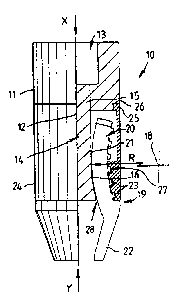
Referring to the drawings and firstly to Figs. 1
to 6 there i:~ illustrated an adjustable gripping device 10
according to the present invention, including a body 11
having a central axis 12 and being provided at one end with
a central square recess 13 adapted to be engaged by a
correspondingly shaped tang of a driving tool or wrench.
Secured to the bod~r 11 or formed integrally therewith is a
guide 14 which extends axially of the body 11 along the
axis 12.
The guide 14 is, as apparent in Fig. 6 of
generally tri.angu.lar cross section at its end adjacent the
SUBSTITUTE SHEET l
~13~400 p~l~u ~ 3 / 0 0 2 ° 0
(~~CFIVED 2 ~ ~ U ! 1
body 11 to form a stem 15 which is connected to the body
11. At its opposite end the guide 14 defines three
longitudinall~~r extending arcuate slideways or slide
surfaces 16. As is apparent, the slideways 16 are arranged
5 about the axis 12 with adjacent slideways 16 disposed at an
acute angle to each other and are separated from each other
by longitudinally extending ribs 17, the ribs 17 at the
free end of the guide 14 having outer arcuate surfaces
centred on the axis 12. Both the slideways 16 and ribs 17
flare outwardly towards the free end of the guide 14 so as
to lie along arcs centred on, and at a radius R from, an
axis 18 located outwardly of the slideways 16 and extending
normal to the central axis 12 of the body 11 and guide 14.
Adapted for co-operation with the guide 14 are
three jaws 19, eac h of which includes at one end an arcuate
shank 2f which has an inner surface 21 complementary to the
arcuate surfaces of the slideways 16. Each shank 20 is
adapted to seat within a respective slideway 16 so as to be
slidable longitudinally of the slideway 16 whilst being in
bearing contact t;h~~rewith. Each jaw 19 also includes at
its opposite free end a gripping portion 22 which is
inclined to or extends at an obtuse angle to the shank 20
so as to en!~ble t:he jaws 19 to grip an abject in all
positions as described further below. As shown in Fig. I,
the portions are inclined inwardly towards each other in
the closed position of the device 10. The shank 20 of each
jaw 19 additionally includes on its outer side a plurality
of teeth 23 which are spaced longitudinally along the shank
20 and adapted for co-operation with an adjuster 24.
The adjuster 24 is mounted to the body 11 and
guide 14 for rotation about the central axis. 12. The
adjuster 24 is of: somewhat tubular or sleeve-like form and
includes at one end an annular ring 25 which locates within
a correspondingly shaped annular groove 26 in the end of
the body 11 whereby to allow for rotational movement of the
adjuster 24 relat::ive to the body 11. At its opposite end,
the adjuster 24 is internally helically threaded at 27, the
thread 27 being formed with an increasing pitch diameter
SUBSTITUTE SHEET 1
238400 P~mU ~ .~ / 0 0 2
RECEjVED~ 2 ~ J a L i°Q3
6
from its inner axial end to its outer axial end so as to be
of bell shaped can:~iguration to match the curvature of the
slideways 16 and shanks 20. The teeth 23 of the respective
shanks 20 are engaged by the helical thread 27 to enable
adjusting movement of the jaws 19 as described further
below. As i~~ apparent in Figs. 1 and 3 the adjuster 24 co-
operates wit;z the ribs 17 so as to close the open outer
sides of the slideways 16 and define slots 28 through which
the shanks 20 of t:he jaws 19 project. The jaw shanks 20
are thus constrained in use for movement along the
slideways 16 and beatween the respective ribs 17.
Upon rotation of the adjuster 24 in opposite
directions the ca-operation between the thread 27 and teeth
23 on the adjuster 24 and the jaw shanks 20, respectively
will cause movement of the jaws 19 longitudinally of the
central axis 12 o:E the device 10 between the position of
Fig. 1 and that of Fig. 7. Additionally, as the shanks 20
are moved longitudinally of the body 11 and guide 14 the
co-operation betwe~:n the respective arcuate surfaces of the
slideways 16 and the arcuate surfaces 21 of the jaw shanks
20 will constrain the jaws to move radially inwardly and
outwardly re.Lative to the axis 12.
Thus in the closed position of Figs. 1 and 3, the
jaw shanks 20 are fully retracted and the gripping portions
22 of the jawsll9 are disposed adjacent to each other to
define the minimum gripping size say for gripping the
hexagonal nut or bolt head 29 shown in dotted outline. In
the fully extended position of the jaw shanks 20, the
gripping portions 22 are opened to the position of Figs. 7
and 8 so as to enable gripping of the hexagonal head 30
shown in dotted oaaline. It will thus be apparent that the
described arrangement allows for a large degree of opening
of the jaws 19 so as to enable gripping of a large size
range of bolts o= nuts.
Th.e gripping device 10 of the present invention
is particularly suited to use as a an adjustable socket for
gripping hexagonal nuts or bolt heads. The device 10 of
the invention however may have applications in gripping
SUBSTITUTE SHEET l
2138 4 U 0 ~'~°~'lAU ~~~~ ~' ~ (~ ~ ~ 9
~ECEIV~~~ 2 0 ~ a ~ ~qq3
7
other object~~ such as square sectioned heads of nuts or
bolts. In ouch a configuration, the device 10 may be
provided with two opposite jaws or four or more jaws
arranged about the axis 12 of the device 10.
The gripping portion 22 of the jaws 19 may if
desired by provided on their inner faces with a grip
increasing surface finish for example a grooved finish to
avoid slipping. In an alternative configuration the inner
gripping faces of the gripping portions 22 may have a
convex configwration in cross-section so as to engage an
article to be gripped along the peak of the convex shape.
The outer surface of the adjuster 24 may also suitably be
knurled or provided with other surface finish to facilitate
gripping and tightening by hand or include configurations
to enable ti.ghteni.ng by use of a separate tool. The
adjuster 24 may also be of outwardly flared form to
increase the thic:kn:ess of the wall about the thread 27 and
provide for- convenient gripping. Whilst the body 11 of the
device 10 is described as having a female square recess 13,
it may be provided with a recess of other configurations to
suit a driving tool. or wrench. Alternatively, the body 11
may be provided with a male configuration such as hexagonal
flats on its outer surface or a hexagonal stem to
facilitate gripping by a suitable tool. In yet an
alternative configuration, the body 11 may be formed
integrally with o:r connected, say through a universal
joint, to a wrench or lever arm.
In yet an alternative configuration, the teeth 23
on the jaws 7.9 may be eliminated as may the threads 27 on
the adjuster 24. hongitudinal movement of the jaws 19 may
then be achieved by other activating means which for
example may Engage or be coupled to the rear ends of the
jaws 19 to cause longitudinal movement thereof. Such means
may include a, threaded member whose rotational movement in
opposite directions causes longitudinal movement of the
jaws 19. They jaws 16 in this configuration would still of
course move along an arcuate path as described above.
The device 10 of the invention may also be motor
SUBSTITUTE SHEET
gt,''~I~A~u ~ / ~ ~~1 ? ~ ~?
~;ECE1VED~ 2 ~ ! U L 193
a
actuated or di:iven. For example the body 11 may be coupled
to a power driven tool or the adjuster 24 may be driven
rotatably in ~~ppo:~ite directions by a drive motor or drive
means of any form for gripping an article for use say in
manufacturing operations. Additionally, in some
configurations, the body 11 in the form described may be
eliminated and the guide 14 secured to or comprised in an
alternative form of tool.
Whi_Lst the above has been given by way of
illustrative embodiment of the invention, all such
modifications and variations thereto as would be apparent
to persons skilled :in the art are deemed to fall within the
broad scope and ambit of the invention as herein set forth.
20
,
35
SUBSTITUTE SHEET