Note: Descriptions are shown in the official language in which they were submitted.
2138446
,
MOLDED PARTIAL PRE-SLIT RESEAL
FIELD OF THE INVENTION
The present invention relates generally to a penetrable reseal
member used for sealing a fluid access port of a solution container, and
5 more particularly to a reseal member for use with a blunt cannula to be
inserted therethrough.
BACKGROUND OF THE INVENTION
0 Reseal members are widely used in medical solution containers to
initially seal the container and later to prevent leakage of fluid from a
container during and after the insertion of a cannula or needle to create a
passage so that fluids may be removed or added to the container.
Typically a reseal member includes a generally cylindrical, solid,
rubber body. To add or remove fluids, the reseal member must be pierced
by a sharp cannula or needle. Sharp cannulas or needles are required to
penetrate the reseal member because the reseal member is thick and solid
at the insertion point.
"Accidental needle stick" is a great concern with the use of this type
of reseal member since a sharp cannula or needle is needed to pierce the
solid, rubber body. To overcome this potential danger, sharp cannulas or
needles are being replaced with blunt cannulas. However, a blunt cannula
cannot be inserted into the traditional type of reseal member without
application of undesirably high force, which creates other potential
dangers. The present invention is intended to overcome these potential
dangers as wéll as to present several significant advantages.
2138~41i
SUMMARY OF THE INVENTION
This invention pertains to a resilient reseal assembly used for
sealing and resealing a fluid access port, particularly in a medical solution
5 container.
A fluid access port generally includes a cylindrical, peripheral wall
with open ends. The reseal member of this invention is positioned
within the fluid access port and is fitted in fluid tight relationship with the
wall. The reseal member has an end portion positioned generally at one
10 of the open ends of the peripheral wall preferably the distal and furtherest
from the solution container body so that the reseal member can be
penetrated by a blunt cannula. Thus, fluids may be passed into or
removed from the solution container.
- More specifically this invention relates to a reseal assembly for
5 penetration by an associated blunt cannula. The reseal assembly seals a
fluid port defined by a generally cylindrical wall having an open proximal
end and an open distal end. The reseal assembly includes a resilient body
portion having a generally frustoconical shape including a top surface, a
side surface tapering from a top end to a bottom end, and a bottom surface.
20 The resilient body further has a hollowed core in the resilient body from
the bottom surface. The hollowed core has a generally conical shape
tapering to a hinged region near the top surface. The hollow core defines
two body sections positioned adjacent each other and joined to each other
by at least the hinged region. The side surface of the resilient body has an
2s annular groove circumferentially surrounding the resilient body near the
top end. The reseal assembly further includes a stiff annular collar having
a first inner annular edge and a second
-2138446
inner annular edge. The first inner edge is positionable within
theannular groove of the resilient body so as to hold the top end of the
resilient body. The second inner edge is positioned around the outer
surface of the proximal end of the cylindrical fluid port to secure the collar
5 and resilient body relative to the fluid port.
This invention contemplates that a user may insert a blunt cannula
through the novel reseal member of the present invention with minimal
insertion force. This invention also contemplates that upon passage of a
blunt cannula through the reseal member, the reseal member forms a
0 fluid-tight seal around the cannula so as to prevent leakage of fluids
therethrough. It is further contemplated that upon withdrawal of the
blunt cannula, the reseal member reforms a generally fluid-tight seal (by
virtue of its resilience) so fluids will not pass therethrough.
These and other objects, features, and advantages of this invention
5 are evident from the following description of a preferred embodiment of
this invention with reference to the accompanying drawings.
BRIEF DESCRIPTION OF THE DRAWINGS
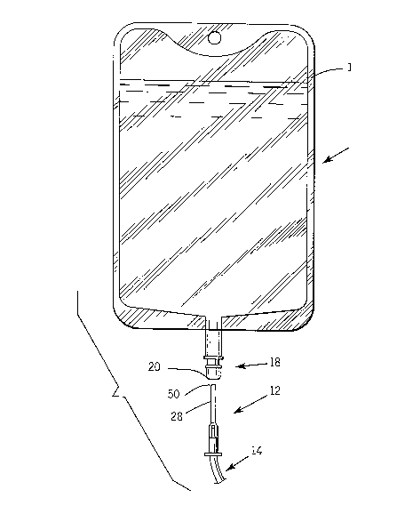
Figure 1 is an elevational view of a solution container with a fluid
port including a reseal member according to the present invention for use
with the blunt entry device;
Figure 2 is a top elevation view of the uncompressed reseal of the
present invention;
Figure 3 is a cross sectional view along line 3-3 of Figure 2 of the
uncompressed reseal according to the present invention;
Figure 4 is a cross sectional view along line 4-4 of Figure 2 of the
uncompressed reseal according to the present invention;
Figure 5 is a bottom elevation view of the uncompressed reseal
-21384~6
member of Figure 2;
Figure 6 is a cross sectional view of the compressed reseal assembly
according to the present invention;
DETAILED DESCRIPTION OF THE PREFERRED EMBODIMENT
While the present invention is susceptible of embodiments in
various forms, there is shown in the drawings and will hereinafter be
described presently preferred embodiments, with the understanding that
the present disclosure is to be considered as an exemplification of the
invention, and is not intended to limit the invention to the specific
embodiments illustrated.
As illustrated in Figure 1 of the drawings, a solution container 10
includes a fluid access port 18 having a reseal assembly 20 according to the
present invention for use in providing fluid communication and sealing
of the solution container. The access port for a flexible fluid container
constitutes one of the preferred embodiments of the present invention,
although other embodiments such as a vial stopper are within the scope of
the invention.
The reseal assembly 20 of the fluid access port 18 may be penetrated
by a blunt entry device such as blunt cannula 12, for example to pass or
withdraw fluids from the container. Blunt entry devices such as the Blunt
Cannula sold by Abbott Laboratories under the registered trademark
Lifeshield(~) are increasingly replacing the sharp needle in many medical
situations.
The novel reseal assembly 20 of the present invention is used to
create a fluid tight seal in a fluid access port 18, such as a port in a thin,
-21~84~6
flexible container 10. The flexible container typically is a poly-
vinylchloride (PVC) intravenous solution container as illustrated in
Figure 1, also referred to herein as an "IV bag". It is preferable to allow
fluids to be passed through the reseal assembly 20, so fluids may be
removed from the container 10, or be added to and mixed with the fluids
in the container 10. Alternatively, the reseal assembly 20 can be used in a
solution vial or in a Y-site of an infusion tubing set.
Flexible bag 10 and attachable plastic tubing 14 are of well known
constructions and as such, will not be described in detail herein. Briefly, as
lo shown in Figure 1, the IV bag 10 includes two plastic sheets bonded
together by a heat seal 16 along the edges of the sheets. Administration
tubing 14, having an axial passage therethrough, is attached to the bag 10
by a blunt cannula 12 that is inserted through a reseal assembly 20
according to the present invention.
Referring now to Figure 6, the reseal assembly 20 includes a reseal
member 22 and a reseal collar 26. The reseal assembly 22 is provided with
a target region 24 which has a reduced resistance to penetration by a blunt
cannula 12, since the target area is partially pierced on the unexposed
inside surface of the reseal. To administer or withdraw fluids through the
reseal assembly 20, the blunt cannula 12 is passed through the reseal
member 22. The reseal member 22 forms a fluid-tight seal around the
blunt cannula 12. Upon withdrawal of the blunt cannula 12, the reseal
member 22 reforms a fluid-tight seal and substantially prevents the
passage of fluids therethrough.
The blunt cannula 12 that is used with the present invention is
becoming increasingly prevalent and preferred in the healthcare industry
for enhancing the efficiency with which solutions are administered to
patients. The cannula 12 has a long, thin shaft 28, for example, a long thin
steel shaft, having an axial passage (not shown) therethrough. The end 30
2138446
.
of the shaft is surface finished so as to create a blunt end. The outside
diameter of the shaft 28 is small, approximately .050-.070 of an inch. The
smooth, blunt end 30 of the cannula 12 is highly effective in preventing a
user from inadvertently being stuck with the end 30 of the cannula 12.
5 Furthermore, the smooth end 30 prevents the blunt cannula 12 from
tearing the interior of the reseal member 20 and desirably acts to prevent
the cannula 12 from creating particulate when the blunt cannula 12 is
passed through the reseal member 20. When the novel reseal assembly
20-of the present invention is used in combination with a blunt cannula
lo 12, a user only needs to exert a minimal amount of force, for example, less
than approximately three pounds of force, to insert the blunt cannula
through the reseal member.
Referring now to Figures 2 - 6, a preferred embodiment of the port
18 and reseal assembly 20 according to the present invention is shown in
5 greater detail.
The reseal member 22 is made of a medical grade resilient material,
for example, rubber or a synthetic elastomeric material. Since the reseal
member 22 is made of this material, the body of the reseal member 22 is
easily displaced by the shaft 28 of the blunt cannula 12 as the cannula
20 passes through the reseal member 22.
Figures 2-5 show the reseal member 22 in the uncompressed
configuration as it is molded. Figure 6 shows the reseal member 22
compressively fitted into the annular reseal collar 26. Collar 26 is then
fitted to the cylindrical access port 18 which further compresses the reseal
25 member 22.
From the side view of Figure 3, reseal member 22 has a generally
frustoconical shape having a top surface 34, a circumferential side surface
36 tapering from the top end to the bottom end, and a bottom surface 38.
213844 6
.
As best seen in Figure 2, the top surface is circular. As best seen in
Figures 2 and 5, the bottom surface 38 is eliptical, in that one axis of the
bottom surface is longer than the other perpendicular axis so as to define
an elipse.
The resilient reseal member 22 also has a hollow core 40 extending
from the bottom surface 38. The hollow core defines a boat-shaped
opening 42 in the bottom surface 38 and has a generally rounded conical
shape as seen in Figures 3 and 4. As best seen in Figure 3, the hollow core
tapers to a hinged region 44 just below the top surface 34 of the reseal
o member.
The side surface 36 has an annular groove 46 into which the inner
annular edge 50 of the reseal collar is fitted.
The reseal member 22 can be molded of a resilient elastomeric
material such as medical grade rubber by conventional molding processes
such as compression molding. Compression molding allows the
tolerances at the hinged region 44 to be better controlled than by the
alternative method of cutting a slit into a rubber member. The molded
configuration of the reseal member 22 can be easily reproduced within
tolerance. Thus, the reseal member 22 will function within the
parameters set for the reseal assembly.
Referring now to Figures 6, the access collar 26 is a hard but flexible
plastic material such as CR3. The collar 26 can also be reproduced by
known molding processes. The collar has an inner annular edge 50 and
an outer annular edge 52. As previously discussed, inner edge 52 is fitted
into the annular circumferential groove 46 molded into the outer conical
surface 36 of the reseal member 22.
The outer annular edge 52 of the collar 26 fits into another annular
groove 54 on the outer surface of the access part 18. The part flexes as the
reseal assembly 20 is inserted therein. The annular outer edge 52 further
-21384~6
compresses the bottom portion of the reseal member 22 as the reseal
assembly 20 is fitted into the cylindrical access port 18.
The fluid access port 18 is preferably made of a flexible, plastic
material and includes a generally cylindrical peripheral wall with a
cylindrical, axial passage therethrough. The port includes an annular
shoulder 60 around the circumference of the wall at a predetermined
distance from an end of the wall.
To insert the collar 26 into the passage 18, an end portion of the wall
is inserted into the passage until the annular shoulder 60 generally abuts
o the end of the passage. Thus, the annular shoulder prevents the reseal
assembly 20 from being completely inserted into the passage. The interior
diameter of the passage and the exterior diameter of the access collar 26 are
approximately the same size so as to create a fluid-tight fit when the collar
is inserted into the passage. The collar may be attached to the passage by
appropriate means.
To insert the reseal member 22 into the fluid access collar 26, the
reseal member 22 is pressed into the access collar a desired distance by a
suitable means. Preferably, the access collar 26 is made of a flexible, plastic
material. Thus, the collar flexes as the reseal member 22 iS placed therein.
The interior diameter of the collar inner edge 50 and the exterior diameter
of the annular groove 46 of reseal member 22 are approximately the same
size so as to create a fluid-tight fit when the reseal member 22 is inserted
into the collar 26.
When the blunt cannula 12 is inserted through the reseal member
22, the body of the reseal member 22 is displaced around the cannula 28
and a fluid-tight seal is formed around the cannula due to the natural
resiliency of the rubber material. Thus, fluids are generally prevented
from leaking through the reseal member 22. The diameter of a blunt
cannula 12 is small and creates a small passage (not shown) through the
-2138446
reseal member 22 when the blunt cannula is inserted. After the blunt
cannula 12 has been completely inserted through the reseal member 22,
fluids can be passed into the container 10 or removed from the container
10, or into tubing if the reseal member 22 is provided in Y-site. When the
5 blunt cannula 12 is withdrawn, the reseal member 22 reforms a generally
fluid-tight seal due to the natural resiliency of the elastomeric material
such as rubber and fluids are substantially prevented from leaking
therethrough.
As best seen in Figure 3, the reseal member 22 is molded of one
0 integral piece and the hinged region 44 defines a preformed partial slit.
The partial slit extends axially from the rearmost end of the reseal member
to a predetermined position near the exposed end of the body and also
across the diameter of the body. To form a partial slit, the two halves of
the reseal body can be integrally formed, with a thin hinged portion 44
5 joining the halves, as shown in Figure 3. The halves can then be urged
together, with the portion 44 acting as a hinge. Thin portion 44 of the
reseal member 22 that is forward of the slit remains as one continuous
piece.
As shown in Figure 3, the region 44 creates an area that, if
20 penetrated by a blunt cannula 12, will allow the blunt cannula to be
inserted into the reseal member 22. This is also commonly referred to as a
"sweet spot." Due to the fact that the preformed slit creates this area, a user
can insert the blunt cannula 12 into any point within the area. If the blunt
cannula 26 is inserted into this area, the blunt cannula will pass through
25 the preformed slit to form the passage.
One feature of note is that the reseal member 22 may include a
raised ridge-like projection to provide a target 24 on the front end portion
of the body. The target aids a user in inserting a blunt cannula 12
21384~6
- 10-
into an area that will cause the blunt cannula to be passed through the
preformed slit of the reseal member 22.
While preferred embodiments have been disclosed above, it is to be
understood that it is within the scope of the invention that any of the
s above embodiments can be easily modified for use in a side port, a down
port, of a solution having a ferrule cap container or in a Y-site of an
infusion tubing set. Furthermore, it is envisioned that more than one
preformed slit may be used in the reseal.
From the foregoing, it will be observed that numerous
0 modifications and variations can be effected without departing from the
true spirit and scope of the novel concept of the present invention. It is to
be understood that no limitation with respect to the specific embodiments
is intended or should be inferred. The disclosure is intended to cover by
the appended claims all such modifications as fall within the scope of the
15 claims.