Note: Descriptions are shown in the official language in which they were submitted.
2138469
.
Figure Coordinate Marking Apparatus
SPECIFICATION
Background of the invention
1. Field of the invention
The present invention relates to a figure coordinate
marking apparatus for marking a specific coordinate position,
such as a centroid of a plane figure onto the plane figure by
tracing along a contour of the plane figure.
2.Background information
In a prior figure coordinate marking apparatus, a specific
coordinate position, such as a known centroid etc. of a known
figure is entered thougll an input device in the main ~ody ~f the
figure coordinate marking apparatus. An internal calculating
device in the figure coordinate marking apparatus calculates the
deviation of coordinates of a marker provided adjacent to a
tracing point by a tracing portion of a measuring lever on the
figure coordinate marking apparatus, from the coordinates of the
figure entered representing the specific coordinates position.
The display device of the figure coordinate marking apparatus
displays the deviation.
The measuring lever is then moved so that the deviation of
the coordinates of the marker from the coordinate of the figuré
entered representing the specific coordinates position becomes
zero on the display, and the marker moved with the measuring
lever then marks the specific coordinate position of the figure
on the figure.
However, if a precise drawing is required, the prior
figure coordinate marking apparatus requires very high skill to
accurately adjust the marker to the specific coordinate position
of the figure, often resulting in error to a great degree.
Also, the privr art has the disadvantage that indication
of the marking point is often unclear even if the marker is
2138469
accurately adjusted to the specific coordinate position of the
figure.
Summary of the invention
With a view to solve the foregoing problems of the prior
art, it is an object of the present invention to provide a figure
coordinate marking apparatus which comprises a fine moving means
capable of easily and accurately adJusting a marker on the figure
coordinate marking apparatus to a specific coordinate position
of a figure with a mar~er capable of clearly marking a point.
A figure coordinate marking apparatus according to the
present invention is comprised of a main body having rollers
provided ~t each end of a horizontal axle perpendicular to the
running direction thereof so that the main body can run in only a
straight running direction, a display device, an input device,
and calculating means. The apparatus further comprises a
measuring lever pivotably supported on the main body to rotate
right or left relative to the running direction in a horizontal
plane. The measuring lever has a marker and a tracing portion
for tracking a figure to be measured to obtain coordinates, area,
length or the like from a figure, from which the calculatin~
means calculates a specific coordinate position of the figure.
The display device indicates any difference between the specific
coordinate position of the figure and a coordinate position of
the marker, and the tracing portion is moved to reduce the
difference to zero.
The figure coordinate mar~ing apparatus further has a
first wheel for fine movement in a running direction of the main
body and a second wheel for ~ine movement in a turning direction
of the measuring lever. ~he first wheel and the second wheel
normally maintains a small distance above a sheet of paper on
which the figure is dra~-n, by an elastic member.
The first wheel can be rotatably supported at an end of
2138~69
~i
the measuring lever by a horizontal a~le perpendicular to a
straight line connecting a supporting fulcrum of the measuring
lever with a tracing point of the tracing portion. Otherwise, the
first wheel can be supported at a center portion of the measuring
lever, the horizontal axle of the first wheel being kept in
parallel with the horizontal axle of the rollers.
The horizontal axle of the first wheel may be kept in
parallel with the rollers by a link arrangement of a belt
e~tending between the first wheel and a supporting fulcrum for
the measuring lever. Otherwise, the horizontal a~le of the first
wheel may be kept in parallel with the rollers by a link
arrangement of bars extending between the first wheel and a
supporti`ng fulcrum for the measuring lever.
The second wheel may be rotatably supported by a
horizontal axle directed toward a supporting fulcrum for the
measuring lever.
The marker can comprise a center needle for pressing a
sheet of paper and a rotating member rotatably supported on the
marker for holding a pencil lead to draw a small circle around
the center needle.
As described above, the measuring lever of the figure
coordinate marking apparatus of the present invention moves near
to the specific coordinate position of the figure in a manner
similar to the prior art. In a final fine movement area, the
first and second wheels rotate while pressed onto the paper
against the elasticity of the elastic member holding them. This
easily and accurately allows make the marker fine movement to the
speci~ic coordinate position of the figure.
After the marker is pointed at the specific coordinate
position of the figure, the center needle of the marker is
pressed on the paper and the ro-tating member holding the pencil
lead rotates a turn. This draws a small circle around the center
~13~469
~,
needle with the center needle being at the center, thereby
allowing the marked point to be easily confirmed after drawing.
It should be noted that after drawing and confirming, the small
circle drawn by the pencil lead can be erased with an eraser to
get rid of excess marks on the figure.
Other objects and advantages and novel features of the
invention will become more apparent from the following portion of
this specification and from the accompanying drawings.
Brief description of the drawings
In the drawings:
Fig. l is a plan view of a first em~odiment of a figure
coordinate marking apparatus according to the present invention;
Fig. 2 is a longitudinal side view of the first embodiment;
Fig. 3 is an end view of the first embodiment;
Fig. ~ is a rear view of the first embodiment;
~ ig. 5 is a plan view of a second embodiment of the figure
coordinate marking apparatus according to the present invention;
Fig. 6 is a longitudinal side view of the second
embodiment;
Fig. 7 is an end view of the second embodiment;
Fig. 8 is a rear view of the second embodiment having a
belt link arrangement;
Fig. 9 is a rear view of a part of the second embodiment
having a link arrangement of bars.
Detailed description of the invention
The following describes a first embodiment of the present
invention by reference to the accompanying drawings.
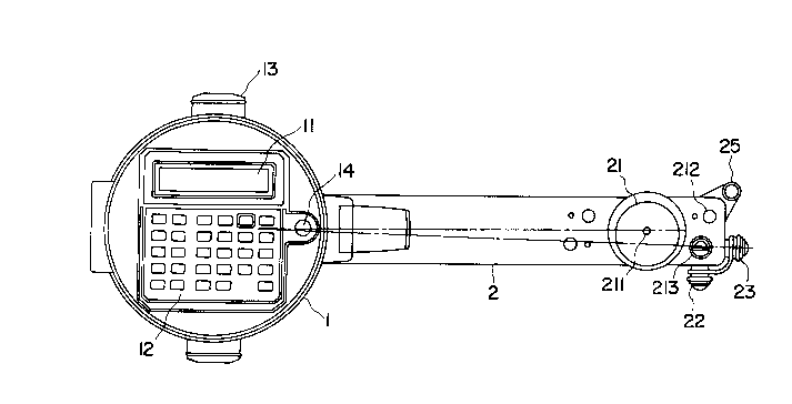
The figure coordinate marl~ing apparatus is comprised of
main body 1 having display device 11, input device 12, internal
calculating device (not shown), rollers 13 rotatably supported on
a side of main body 1 at each end of a straight horizontal axle
2138~69
.~,
perpendicular to a running direction of main body 1 so that main
body 1 can run only in the running direction. The figure
coordinate marking apparatus also comprises measuring lever 2
supported at fulcrum 1~ on main body 1 so as to be turnable right
and left relative to the running direction of main body 1.
Measuring lever 2 has tracing portion 21 at the end
thereof. First wheel 22 for fine movement of the whole
apparatus including main body 1 and measuring lever 2, in the
running direction of main body 1, and second wheel 23 for fine
movement of measuring lever 2 in the turning direction of
measuring lever 2 are respectively supported at the end of
measuring lever 2. Both first wheel 2~ and second wheel 23 are
held by elastic member 2~ IFig. 4) such as, a plate spring or the
like on a rear side of measuring lever 2 to maintain a small
distance above a sheet of paper on which a figure is being drawn.
A horizontal a.Yle of first wheel 22 is held at right
angles to a straight line connecting supporting fulcrum 14 of
main body 1 with tracing point 211 of tracing portion 21 of
measuring lever 2.
A horizontal axle of second wheel 23 is held directly in
line with supporting fulcrum 14.
Further, measuring lever 2 has marker 2~ supported at the
end thereof. Marker 25 is comprised of a center needle for
pressing on a sheet of paper and a rotating member rotatably
connected to and supported on the marker for holding a pencil
lead for drawing a small circle around the center needle.
Any difference between the coordinate positions of mar~er
25 and tracing point 211 are stored as data in a calculating
device (not shown~. The calculatin~ devicç calculates a specific
coordinate position of a figure to be measured and also a
difference between the specific coordinate position of the figure
and a coordinate position of mar~er 25 using the above data
2138469
stored in the calculating device as an offset. Display device 11
displays the specific coordinate position and the difference to
show a point where marker 25 should be positioned.
In turn, the following describes the operation of the
figure coordinate ~arking apparatus. Input device 12 is used to
enter calculation commands for calculating specific coordinate
positions of the figure, such as a centroid of the fi~ure. After
that, tracing point 211 is moved along the contour of the figure
to obtain and store X and Y coordinates of minutely sectioned
positions of the contour of the figure in the calculating device.
As the figure is sectioned minutely enough, it performs a
continuous measurement.
If the figure to be measured is defined by a plurality of
straight lines, a representation of the figure is entered before
measurement. The tracing point is then moved to verte.~es of the
figure defined by straight lines, coordinates of which are read
when a coordinate read button is pressed. Tracing along the
contour of the figure between the verteYes can be omitted on the
way from a vertex to a next verte~.
A continuous measurement selector button 212 provided at
the end of measuring lever 2 is used to select each
representative measurement of the figure or the continuous
measurement of figure. If a figure to be measured is defined by
a plurality of straight lines, coordinate read button 213 is
pressed at vertex positions of the figure, thereby enterin the
coordinates of the vertexes into the calcuiating device.
After the coordinates along the contours or all the
verte.Yes of the fig~re are read, display device 11 displays the
necessary data.
The necessar~- data are the specific coordinates of, for
exampie, the centroid of the figure and the coordinates of a
current ~arker position and a difference between the specific
2138469
coordinates and the coordinates of the marker. Measuring lever 2
is moved until the difference is zero so that a position of the
mar~er goes to the specific coordinate position.
In this case, as it is difficult to precisely move marker
25 to a specific coordinate position, first wheel 22 or second
wheel 23 is utilized to accurately move the mar~er near the
specific coordinate position. Though the first and second wheels
22, 23 are normally kept a small distance above the sheet of
paper on which a figure is being drawn by elastic member 2~, they
can be pressed toward the paper and rotated on it so that the
marker can be easily and accurately moved to coincide with the
specific coordinate position.
Fig. 5 is a plan view of a second embodiment of the figure
coordinate marking apparatus according to the present invention,
Fig. 6 is a longitudinal side view of the second embodiment, Fig.
7 is an end view of the second embodiment, and Fig. 8 is a rear
view of the second embodiment.
The figure coordinate mar~ing apparatus comprises main
body 1 having display device 11, input device 12, internal
calculating device (not shown3, rollers 13 rotatably supported on
a side of main body 1 at each end of a straight horizontal axle
perpendicular to a running direction of main body 1 so that main
body 1 can run only in the running direction. The figure
coordinate marking apparatus also comprises measuring lever 3
supported b~- fulcrum 1~ on ~ain bod~- 1 so as to be turnable right
and left relative to the running direction of main body 1.
Measuring lever 3 has tracing portion 31 at the end
thereof. ~easuring lever 3 also has second wheel 33 for fine
movement of measuring lever 3 in the turning direction of
measuring lever 3. Second wheel 33 is held by eLastic member 3~
such as a plate spring or the like disposed on a rear side of
measuring lever 3 to maintain a small distance above the sheet of
21 38~69
'~,
paper on which a figure is being drawn.
First wheel 32 is supported at a center of measuring lever
3 for fine movement of the whole apparatus including main body 1
and measuring lever 3, in the running direction of main body 1.
Further, fixed wheel 141 (Fig. 8) is fixed to supporting fulcrum
1~ and slave wheel 142 having the same diameter as fixed wheel
141 is fixed to a horizontal axle of first wheel 32 for rotating
the horizontal axle of first wheel 32 around a vertical axle on a
horlzontal plane. Unslidable belt 35 which is for example a
timing belt or the like extending between fixed wheel 1~1 and
slave wheel 142 constitutes a link arrangement.
It should be noted that slave wheel 1~2 and first wheel
32 are normally kept a small distance above a sheet of paper on
which a figure to be measure is drawn by an elastic member (not
shown), as in the first embodiment described above.
Fig. 9 is a rear view of another link arrangement
comprised of two bars 36 in place of the link arrangement of belt
35 of Fig. 8. Both ends of each of two bars 36 are turnably held
in place. Namely one end of each bar 36 is turnably attached to
main body 1 while the other end of each bar 36 is turnably
,.
attached to a disk fixed the horizontal axle of first wheel 32.
Distances between fulcrums of the both ends of two bars 36 are
set equal so that the horizontal a~le of first wheel 32 and an
axle of roller 13 of main body 1 can be kept parallel
irrespective of the turning angle of measuring lever 3. As other
arrangements are the same as in the first embodiment, detailed
description of them is omitted here.
Opera~ion of the second embodiment is identical with the
operation of corresponding parts in the first embodiment except
for first wheel 32.
As described above, the horizontal axle of flrst wheel 32
and the axle of roller 13 of main body 1 can be kept parallel
2138~69
,,
irrespective of the turning angle of measuring lever 3, therefore
when first wheel 32 is pressed to move on a sheet of paper to be
drawn, a moving direction of measuring lever 3 can coincide with
the direction of movement of roller 13, while being independent
from a turning angle of measuring lever 3.
As described so far, the figure coordinate marking
apparatus of the present invention can calculate a specific
coordinate position of a figure to be measured, such as the
centroid on the figure, by means of the calculating device. The
apparatus also displays a difference of a current position of the
marker from the specific coordinate position of the figure. The
measuring lever is moved until tne difference is zero.
In that case, if the difference approaches zero, the first
and second wheels are used for fine movement of the measuring
lever so that the marker can easily and accurately come to the
specific coordinate position of the figure.
The marker that is of the so-called compass type can
clearly point the position to be marked by the position of the
center needle and a small circle drawn around the center needle
with the pencil lead. The small circle can be erased with an
eraser when it i5 not needed.
While the principles of the invention have been described
above in connection with specific embodiments, and particular
modifications thereof, it is to be clearly understood that this
description is made only by way of example and not as a
limitation on the scope of invention.