Language selection

Search

Patent 2138771 Summary

Third-party information liability

Some of the information on this Web page has been provided by external sources. The Government of Canada is not responsible for the accuracy, reliability or currency of the information supplied by external sources. Users wishing to rely upon this information should consult directly with the source of the information. Content provided by external sources is not subject to official languages, privacy and accessibility requirements.

Claims and Abstract availability

Any discrepancies in the text and image of the Claims and Abstract are due to differing posting times. Text of the Claims and Abstract are posted:

  • At the time the application is open to public inspection;
  • At the time of issue of the patent (grant).
(12) Patent Application: (11) CA 2138771
(54) English Title: APPARATUS
(54) French Title: APPAREIL
Status: Deemed Abandoned and Beyond the Period of Reinstatement - Pending Response to Notice of Disregarded Communication
Bibliographic Data
Abstracts

English Abstract

2138771 9400644 PCTABS00030
The invention relates to a device for handling material,
especially soil, the device comprising a bucket (1) of a machine having a
grinding device (2) for the material fitted thereto, the
grinding device comprising at least two essentially parallel shafts (3)
which are set at a distance from each other and rotatable in
synchronization, the shafts comprising grinding members (4) for the
material, whereby the grinding members (4) of two adjacent shafts
overlap each other, the bottom of the bucket (1) comprising an
outlet opening (5) for the handled material. According to the
invention the grinding members are comprised of numerous discs (4)
which are set at a distance from each other on each shaft (3), the
peripheral surfaces of the discs comprising projections, whereby a
notch is provided between two adjacent projections. In addition,
the bucket (1) comprises a loosening device (6) for the material
fitted between the grinding device (2) and the outlet opening
(5), the loosening device comprising at least two essentially
parallel shafts (7) which are set at a distance from each other and
rotatable in synchronization and which comprise aeration blades (8)
for loosening the ground material obtained from the grinding
device (2).


Claims

Note: Claims are shown in the official language in which they were submitted.

WO 94/00644 PCT/FI93/00268
CLAIMS
1. A device for handling material, especially soil, comprising a
bucket (1) of a machine having a grinding device (2) for
material fitted thereto, the grinding device comprising at least
two essentially parallel shafts (3) which are set at a distance
from each other and rotatable in synchronization, the shafts
comprising grinding members (4) for the material, whereby the
grinding members (4) of two adjacent shafts overlap each other,
the bottom of the bucket (1) comprising an outlet opening (5)
for the handled material, c h a r a c t e r i z e d in that the
grinding members consist of numerous discs (4) which are set at
a distance from each other on each of the shafts (3), the
peripheral surfaces of the discs comprising projections (9),
whereby a notch (10) is provided between two adjacent
projections, and that the bucket (1) further comprises a
loosening device (6) for the material fitted between the
grinding device (2) and the outlet opening (5), the loosening
device comprising at least two essentially parallel shafts (7)
which are set at a distance from each other and rotatable in
synchronization and which include aeration blades (8) for
loosening the ground material obtained from the grinding device
(2).
2. A device according to Claim 1, c h a r a c t e r i z e d in
that the discs (4) comprise essentially a tooth-like
configuration.
3. A device according to Claim 2, c h a r a c t e r i z e d in
that the teeth (9) comprise a widening part (11).
4. A device according to Claim 3, c h a r a c t e r i z e d in
that the widening part (11) extends from the tooth (9) to the
adjacent notch (10) which is situated after the tooth (9) in the
direction of rotation of the disc (4).
5. A device according to any of the preceding Claims,
c h a r a c t e r i z e d in that the shafts (3) of the
grinding device comprise a polygonal, preferably hexagonal

WO 94/00644 PCT/FI93/00268
shape, and that the discs (4) comprise a corresponding polygonal
bore (12).
6. A device according to any of the preceding Claims,
c h a r a c t e r i z e d in that between two adjacent discs on
the same shaft, spacing sleeves are fitted around the shaft, the
steel being pressed between the spacing sleeves.
7. A device according to any of the preceding Claims,
c h a r a c t e r i z e d in that the aeration blades (10)
comprise an essentially propeller-like shape.

Description

Note: Descriptions are shown in the official language in which they were submitted.


W094/00~ 2 ~ ï r1 i PCT/Fl93J00268
PARATUS .
The invention relates to a device for handling material,
especially soil, the device consisting of a bucket of a machine
having a grinding device for material fitted thereto, the
grinding device comprising at least two essentially parallel
shafts which are at a distance from each other and rotatable in
synchronization, the shafts comprising grinding members for the
material, whereby the grinding members of two adjacent shafts
overlap each other, the bottom of the bucket comprising an
outlet opening for the handled material.
The materials to be handled include, in particular, different
soils such as compost, peat, and waste soil as well as different
waste materials.
The bucket of the above described type which is especially
intended to be used as the bucket of an excavator and for
grinding soil, is known from FI patent application 902469. The
- grinding members on the shafts of the grinding device in this
known bucket construction consist of radial blades welded on the
shafts which mix and grind the soil to be handled. A
disadvantage of this construction is that the blade can be
twisted by stones or the like resulting in ~he twisted blade
colliding with the blade on the adjacent shaft, whereby the
bucket must be stopped and removed for repair. Another
di~advantage of the described construction is that roots or the
like can become tangled with the blades resulting in jamming the
device. The handled soil would not be very loose, either, nor
would it be sufficiently high-quality for demanding uses~
Screening plants are also well known which handle compost using
large drum screens. Such plants are very expensive and require
separate transporting equipment if they are to be transferred
from one place to another.
The purpose of this invention is to provide a device which
avoids the above-described drawbacks of known devices, and the

W094/oo~ ~ i 3, ? 7 . PCT/FI93/00268
purpose cf the invention is namely to provide a device which is
very reliable and comprises a minimum number of parts which wear
and are apt to break, and which, in addition to effectively
screening and grinding the material to be handled, also renders
it a loo~e form.
An important object of the invention is thus to provide a device
which produces very high-quality soil which suits demanding uses
very well.
These objecks can be realized by the device according to the
invention, the main characteristics of which are disclosed in
the appended Claims.
The invention is based on the realization that a bucket
construction is provided comprising a grinding device which
includes effective and strong grinding members and which screens
and grinds the material to be handled, and a loosening device
which renders the screened and ground material in a loose form
resulting in very high-quality material.
Thus the bucket according to the invention, which preferably is
a bucket of a wheel loader, comprises a grinding device for the
material fitted to the bucket, the grinding device including at
least two, preferably four, essentially parallel shafts which
are at a distance from each other and rotatable in
synchronization and which comprise grinding members for the
material consisting of numerous discs which are at a distance
from each other on each shaft, the discs having projections on
the peripheral surface thereof, whereby a notch is provided
bètween two adjacent ~projections. The grinding members of the
two adjacent shafts overlap each other. The bottom of the bucket
is provided with an outlet opening for the handled material.
As described above, the bucket according to the invention
further comprises a loosening device which is fitted between the
grinding device and the outlet opening and which comprises at
least two, preferably two, essentially parallel shafts which are
at a distance from each other and rotatable in synchronization,

Y; i 7 ~
W094/00~ PCT/~193/00268
including aeration blades for loosening the ground material. The
aeration blades are preferably shaped like propellers.
According to the invention, also a bar screen can be fitted into
the bucket which screens, for example, stones, stubs, roots and
similar large-size items out of the compost. Such a bar screen
is fitted above the shafts of the grinding device, preferably so
that the ribs of the bar screen are between the planar parts of
the overlapping discs.
The above-mentioned discs preferably comprise an essentially
tooth-like shape and according to a preferred embodiment of the
invention, the teeth comprise a widening part extending from the
tooth to the notch situated after the tooth in the direction of
rotation of the disc.
According to the in~ention, the shape of the shafts of the
grinding device is preferably polygonal, especially preferably
hexagonal, whereby the discs comprise a corresponding polygonal
bore. This construction ensures that the discs are rotated along
with the shaft.
In order to keep the desired distance between the discs on the
same shaft, a spacing sleeve with a length corresponding to the
desired distance between the discs can be fitted between the
discs and around the shaft.
The grinding device and the loosening device are driven by
hydraulic motors which are connected to the hydraulic system of
the machine. The shafts of the grinding device are
: `
advantageously rotated in the same direction, the speed of
rotation being typically about lO0 to 150 rpm. The shafts of the
loosening device are rotated at a considerably higher velocity
than the shafts of the grinding device, the typical speed of
rotation being about 400 to 500 rpm. Depending on the
construction of the aeration blades, the shafts of the loosening
device can be rotated either in the same direction or in
different directions.

W094/00~ 7 7 1 PCT/F193/00~68
In the following the invention is described in more detail with
reference to the appended drawings, in which:
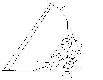
Fig. 1 represents a simplified section of a preferred bucket
s according to the invention,
Fig. 2 represents the same construction, as in Fig. 1, in a
partial view as viewed from the mouth of the bucket,
Fig. 3 represents a detail shown in Fig. 1 in an enlarged scale,
and
Fig. 4 represents the same construction as in Fig. 3 as viewed
from another direction.
Referring to Fig. 1, the bucket of a wheel loader is generally
marked with reference number 1. The bottom of bucket 1 comprises
outlet opening 5 for the material.
Bucket 1 comprises grinding device 2 for the material, loosening
device 6 for the ground material being fitted below it.
Grinding machine 2 compri~es, in this instance, four essentially
planar, essentially parallel shafts 3 which are at a distance
from each other and rotatable in synchronization. Shafts 3 are
preferably rotated in the same direction by a hydra~lic motor
(not shown in ~he Figs.) using conventional transmissions. The
hydraulic motor is connected to the hydraulic system of the
wheel loader.
A large number of discs 4 are fitted to shafts 3 and set at a
distance from each other. Shafts 3 extend from one side portion
of the bucket to the other one. Shafts 3 and discs 4 on them are
fitted with respect to each other in such a way that the discs
of the second shaft are laterally displaced with respect to the
discs of the first shaft so that the disc of the first shaft is
in the middle of two adjacent discs of the second shaft. In
addition, the discs of two adjacent shafts overlap each other.
The discs of the third shaft are aligned with the discs of the
first shaft and the discs of the fourth shaft are aligned with
the discs of the second shaft.

W094/00~ C~J 1 3 7 7 . PCT~Fl93/00268
The material taken into bucket 1 is subjected to grinding device
2 which serves as a coarse screen taking, for instance, stones,
stubs, and roots and other large-size parts out of the compost.
Grinding machine 2 comprises rotating discs which grind
~ material. The screened and ground material is then subjected to
loosening device 6 which in this example comprises two
essentially parallel shafts 7 which are set at a distance from
each other and rotatable in synchronization, including
propeller like aeration blades 8. Shafts 7 are rotated with the
aid of a hydraulic motor (not shown) which is connected to the
hydraulic system of the wheel loader. The screened,, ground and
loosened material obtained from loosening device 6 :is extremely
fine-grained and high-quality.
Figs. 3 and 4 show a preferred shape of discs 4. These discs 4
granulate and grind material very effectively. Discs 4 mainly
consist of a tooth-like shape comprislng, in this example, six
teeth and six notches between the teeth, respectively. Each
tooth 9 has a widening part 11 attached thereto and extending
from tooth 9 to adjacent notch 10 which is situated after tooth
9 in the direction of rotation of disc 4. Widening part 11 is
formed of a rectangular metal piece comprising a chain link the
width of which corresponds to the thickness of the disc. This
widening part 11 is welded to disc 4. While discs 4 rotate,
widening parts 11 take the material on top of the discs to the
space below the discs where loosening de~ice 6 is situated.
Shafts 3 of grinding device 2 preferably comprise a hexagonal
shape, whereby discs 4 çorraspondingly comprise a hexagonal
opening 12 for the shaft (see Fig. 3). Due to this -:~nstruction
discs 4 rotate in a controlled manner alo~-~ witn shafts 3.
Spacing sleeves are fitted between adjacent e~.scs 4 around the
shaft. The end sleeves of the shafts are attached to the shaft,
for instance, by welding or in another manner. If one of the
discs for one reason or another must be replaced with another
one, this is simply done by opening the end sleeve fastener and
taking away the desired number of sleeves and discs from the
shaft and then the desired numbe- of discs and sleeves are

W094/00~4 213 ~ 17 1 PCT/F193/OU268 ~
refitted on the shaft.
Using the bucket according to the invention, compost or like
material can be lifted straight from the ground and discharged
through a grinding device and a loosening device onto the body
of a truck, for instance. Correspondingly, using the bucket
according to the invention compost or like material can be
lifted, for instance, from the body of a truck and discharged
through a grinding device and a loosening device straight to the
ground.

Representative Drawing
A single figure which represents the drawing illustrating the invention.
Administrative Status

2024-08-01:As part of the Next Generation Patents (NGP) transition, the Canadian Patents Database (CPD) now contains a more detailed Event History, which replicates the Event Log of our new back-office solution.

Please note that "Inactive:" events refers to events no longer in use in our new back-office solution.

For a clearer understanding of the status of the application/patent presented on this page, the site Disclaimer , as well as the definitions for Patent , Event History , Maintenance Fee  and Payment History  should be consulted.

Event History

Description Date
Inactive: Adhoc Request Documented 2018-06-06
Revocation of Agent Requirements Determined Compliant 2018-05-18
Appointment of Agent Requirements Determined Compliant 2018-05-18
Inactive: IPC from MCD 2006-03-11
Application Not Reinstated by Deadline 2002-06-25
Time Limit for Reversal Expired 2002-06-25
Inactive: Abandoned - No reply to s.30(2) Rules requisition 2001-08-27
Deemed Abandoned - Failure to Respond to Maintenance Fee Notice 2001-06-26
Inactive: S.30(2) Rules - Examiner requisition 2001-02-27
Amendment Received - Voluntary Amendment 2000-11-01
Inactive: Application prosecuted on TS as of Log entry date 2000-07-06
Letter Sent 2000-07-06
Inactive: Status info is complete as of Log entry date 2000-07-06
All Requirements for Examination Determined Compliant 2000-05-24
Request for Examination Requirements Determined Compliant 2000-05-24
Application Published (Open to Public Inspection) 1994-01-06

Abandonment History

Abandonment Date Reason Reinstatement Date
2001-06-26

Maintenance Fee

The last payment was received on 2000-05-24

Note : If the full payment has not been received on or before the date indicated, a further fee may be required which may be one of the following

  • the reinstatement fee;
  • the late payment fee; or
  • additional fee to reverse deemed expiry.

Please refer to the CIPO Patent Fees web page to see all current fee amounts.

Fee History

Fee Type Anniversary Year Due Date Paid Date
MF (application, 4th anniv.) - small 04 1997-06-23 1997-06-05
MF (application, 5th anniv.) - small 05 1998-06-23 1998-06-04
MF (application, 6th anniv.) - small 06 1999-06-23 1999-05-31
MF (application, 7th anniv.) - small 07 2000-06-23 2000-05-24
Request for examination - small 2000-05-24
Owners on Record

Note: Records showing the ownership history in alphabetical order.

Current Owners on Record
MIKKO YRJOLA
Past Owners on Record
None
Past Owners that do not appear in the "Owners on Record" listing will appear in other documentation within the application.
Documents

To view selected files, please enter reCAPTCHA code :


To view images, click a link in the Document Description column. To download the documents, select one or more checkboxes in the first column and then click the "Download Selected in PDF format (Zip Archive)" or the "Download Selected as Single PDF" button.

List of published and non-published patent-specific documents on the CPD .

If you have any difficulty accessing content, you can call the Client Service Centre at 1-866-997-1936 or send them an e-mail at CIPO Client Service Centre.


Document
Description 
Date
(yyyy-mm-dd) 
Number of pages   Size of Image (KB) 
Abstract 1995-11-11 1 54
Cover Page 1995-11-11 1 20
Claims 1995-11-11 2 82
Drawings 1995-11-11 2 38
Description 1995-11-11 6 330
Representative drawing 1998-07-28 1 5
Reminder - Request for Examination 2000-02-24 1 119
Acknowledgement of Request for Examination 2000-07-06 1 177
Courtesy - Abandonment Letter (Maintenance Fee) 2001-07-24 1 182
Courtesy - Abandonment Letter (R30(2)) 2001-11-05 1 171
Fees 2000-05-24 1 36
PCT 1994-12-21 7 257
Fees 1997-06-05 1 47
Fees 1998-06-04 1 34
Fees 1999-05-31 1 35
Fees 1996-06-05 1 47
Fees 1995-06-16 1 65