Language selection

Search

Patent 2138861 Summary

Third-party information liability

Some of the information on this Web page has been provided by external sources. The Government of Canada is not responsible for the accuracy, reliability or currency of the information supplied by external sources. Users wishing to rely upon this information should consult directly with the source of the information. Content provided by external sources is not subject to official languages, privacy and accessibility requirements.

Claims and Abstract availability

Any discrepancies in the text and image of the Claims and Abstract are due to differing posting times. Text of the Claims and Abstract are posted:

  • At the time the application is open to public inspection;
  • At the time of issue of the patent (grant).
(12) Patent Application: (11) CA 2138861
(54) English Title: STORAGE COMPARTMENT FOR AN AUTOMOTIVE VEHICLE
(54) French Title: COMPARTIMENT DE RANGEMENT POUR VEHICULE AUTOMOBILE
Status: Deemed Abandoned and Beyond the Period of Reinstatement - Pending Response to Notice of Disregarded Communication
Bibliographic Data
(51) International Patent Classification (IPC):
  • B60R 7/04 (2006.01)
(72) Inventors :
  • NICOPOLIS, MICHAEL D. (United States of America)
(73) Owners :
  • FORD MOTOR COMPANY OF CANADA, LIMITED
(71) Applicants :
  • FORD MOTOR COMPANY OF CANADA, LIMITED (Canada)
(74) Agent: MARKS & CLERK
(74) Associate agent:
(45) Issued:
(22) Filed Date: 1994-12-22
(41) Open to Public Inspection: 1995-06-28
Availability of licence: N/A
Dedicated to the Public: N/A
(25) Language of filing: English

Patent Cooperation Treaty (PCT): No

(30) Application Priority Data:
Application No. Country/Territory Date
08/172,783 (United States of America) 1993-12-27

Abstracts

English Abstract


An auxiliary storage compartment for an
automobile has a compartment body with a pair of side
portions and a substantially horizontal floor portion
forming a U-shaped opening. The compartment body is
rigidly attached to the roof and extends laterally across
the width of the vehicle above the cargo storage area. The
side portions, floor portion and the vehicle roof define a
compartment therebetween. A bezel member, having at least
one opening therein, is connected to compartment body and
enclosing the U-shaped opening between the roof and the
compartment body. At least one door is movably attached to
the bezel opening for enclosing and providing access to the
compartment. A latching mechanism on the door secures the
door in a closed position.


Claims

Note: Claims are shown in the official language in which they were submitted.

- 5 -
The embodiments of the invention in which an exclusive
property or privilege is claimed are defined as follows:
1. An auxiliary storage compartment for an
automotive vehicle having two longitudinally spaced seating
positions and a cargo storage area spaced longitudinally
rearwardly of said seating positions, said compartment
comprising:
a compartment body having a pair of side portions
and a substantially horizontal floor portion forming a U-
shaped opening, said compartment body rigidly attached to
the roof and substantially extending across the width of
the vehicle above the cargo storage area, said side
portions, floor portion and the vehicle roof defining a
compartment therebetween;
a bezel member connected to compartment body and
enclosing said U-shaped opening between the roof and said
compartment body and having at least one opening therein;
at least one door movably attached to said bezel
in said opening for enclosing and providing access to said
compartment; and
latching mechanism on said door for securing said
door in a closed position.
2. An auxiliary storage compartment as recited in Claim 1
wherein said roof further comprises a headliner, said
compartment body connected to said roof so that the
headliner is between the roof and said compartment body.
3. An auxiliary storage compartment as recited in Claim 1
wherein said latching mechanism includes a key activated
lock.
4. An auxiliary storage compartment as recited in Claim 1
wherein said side portions and said floor portions are
integrally molded.

- 6 -
5. An auxiliary storage compartment as recited in Claim 1
wherein said cargo storage area further comprises a
transversely mounted header member extending thereacross,
said compartment body also being connected to said header
member.
6. An auxiliary storage compartment as recited in Claim 1
further comprising a foam rubber material layer on the
upper surface of said floor portion inside said
compartment.
7. An auxiliary storage compartment as recited in Claim 1
wherein said bezel further comprises two openings, said
openings spaced apart by a vertical support portion
integral with said bezel.
8. An auxiliary storage compartment as recited in Claim 1
wherein said bezel opening defines a ledge with said floor
portion.
9. An auxiliary storage compartment as recited in Claim 1
wherein said compartment further comprises a vertical wall
member extending transversely across said compartment
between the roof and said floor portion.
10. An auxiliary storage compartment as recited in Claim 1
wherein said compartment further comprises a vertical wall
portion extending longitudinally through said compartment
between the roof and said floor portion.
11. An auxiliary storage compartment as recited in Claim 1
further comprising a fabric insert on the underside of said
floor portion.

- 7 -
12. An auxiliary storage compartment as recited in Claim 1
wherein said door further comprises biasing means for
urging the doors toward an open position.
13. An auxiliary storage compartment for an automotive
vehicle having two longitudinally spaced seating positions,
a cargo storage area spaced longitudinally rearwardly of
said seating positions and a transversely mounted header
member across the most rearward portion of the cargo
storage area, said compartment comprising:
a compartment body having a pair of tapered side
portions of decreasing heights and a floor portion forming
a U-shaped opening, said side portions of said compartment
body rigidly attached to the roof and said floor portion
having a lower surface substantially coplanar with the
lowermost surface of said header extending horizontally
from and rigidly attached to the transversely mounted
header member so that said compartment body substantially
extends laterally across said vehicle above the cargo
storage area, said side portions, said floor portion, the
transversely mounted header member and the vehicle roof
defining a compartment having an opening therebetween.
14. An auxiliary storage compartment as recited in Claim
13 further comprising a bezel member connected to said
compartment body and enclosing said U-shaped opening.
15. An auxiliary storage compartment as recited in Claim
13 further comprising at least one door movably attached to
said bezel in said opening for enclosing and providing
access to said compartment.
16. An auxiliary storage compartment as recited in Claim
15 wherein said door is attached by a spring for biasing
said door in an open position.

- 8 -
17. An auxiliary storage compartment as recited in
Claim 13 further comprising latching means on said door for
securing said door in a closed position.
18. An auxiliary storage compartment as recited in Claim
13 said roof further comprising a headliner, said
compartment body connected to said roof so that the
headliner is between the roof and said compartment body.
19. An auxiliary storage compartment as recited in Claim
13 wherein said bezel further comprises two openings, said
openings spaced apart by a vertical support portion
integral with said bezel.
20. An auxiliary storage compartment as recited in Claim
13 further comprising a rubberized mat on the inside
surface of said floor portion of said compartment.

Description

Note: Descriptions are shown in the official language in which they were submitted.


` ~138861
STORAGE COMPARTMENT FOR AN AUTOMOTIVE VEHICLE
BACKGROUND OF THE INVENTION
The invention relates generally to a storage
compartment for an automotive vehicle and more specifically
to an auxiliary storage compartment mounted over a rearward
cargo area.
In an automotive vehicle, especially in a
sport/utility vehicle, a need exists to maximize the
storage space without intruding on the passenger space.
One solution is to mount a console between the front seats
as disclosed in U.S. Patent 5,062,559.
In a sport/utility type vehicle generally there
are two rows of seating. Behind the second row of seating
is a cargo storage area. An unutilized space exists
between the roof and the driver's rearward sight line.
It would be desirable to provide a storage
compartment in the unutilized portion of an automotive
vehicle over the rearward cargo storage area without
reducing the passenger space.
SUMMARY OF THE INVENTION
An advantage of the present invention is that a
storage compartment is provided in the previously
unutilized space above the cargo storage area without
interfering with the driver's rearward sight line.
A preferred embodiment of the present invention
includes a compartment body with a pair of side portions
and a substantially horizontal floor portion forming a U-
shaped opening. The compartment body is rigidly attached
to the roof and extends laterally across the width of the
vehicle above the cargo storage area. The side portions,
floor portion and the vehicle roof define a compartment
therebetween. A bezel member, having at least one opening
therein, is connected to compartment body and enclosing the
U-shaped opening between the roof and the compartment body.
At least one door is movably attached to the bezel opening
for enclosing and providing access to the compartment. A

2138861
-- 2
latching mechanism on the door secures the door in a closed
position.
BRIEF DESCRIPTION OF THE DRAWINGS
FIG. 1 is a perspective view of an automotive
vehicle having a compartment according to the preferred
embodiment of the invention.
FIG. 2 is a longitudinal cross sectional view of
the preferred embodiment.
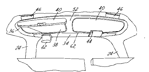
FIG. 3 is a front view of the preferred
embodiment.
FIG. 4 is a top view of the preferred embodiment.
DETAILED DESCRIPTION OF THE PREFERRED EMBODIMENT
Referring now to FIG. 1, an automotive vehicle
10, such as a sport/utility vehicle or station wagon, is
illustrated as including a passenger compartment 11 with
two rows of longitudinally spaced seats 12. Rearwardly
spaced from seats 12 is a cargo storage area 14. A
compartment 30 extends over cargo storage area 14.
Referring now to FIGS. 1 and 2, pillars 24 which
are generally located at the corners of passenger
compartment 11 and at least one additional pillar 24 on
either side of vehicle 10. Pillars 24 are used to support
structural members such as the header 18 which extends
across the rear of vehicle 10 and is used to support roof
20. Roof 20 slopes down slightly as it extends back to
header 18.
Header 18 extends down slightly below roof 20. A headliner
22 lines the interior of roof 20.
Referring now to FIGS. 2 and 3, access to cargo
storage area 14 is provided from the outside of vehicle 10
through external cargo door 16. Header 18 extends above
door 16 and has a lower surface 19 defining the lowest
rearward sight line. The space between the driver's sight
line and headliner 22 on roof 20 is unutilized in such

2138861
- 3 -
vehicles. To increase the usable storage space for vehicle
10, a compartment 30 is formed above cargo storage area 14
and the driver's sight line.
Compartment 30 is defined by two longitudinal
side walls 32 and a floor member 34. Side walls 32 are
tapered to the slope of roof 20 in order to position floor
member 34 in a generally horizontal plane with header 18.
Longitudinal side walls 32 are connected to the sides of
floor member 34 forming a substantially U-shaped opening in
the forwardmost portion of compartment 30. The rearmost
portion of compartment 30 uses header 18 for enclosure. It
is preferred that floor member 34 and longitudinal walls
are integrally formed, however, they may be formed as
separate components. One method of integrally forming
compartment 30 is to blow mold it from polyethylene.
A bezel 36 is used to enclose the front U-shaped
opening of compartment 30. Bezel 36 has at least one
opening 38. However, bezel 36 is preferably provided with
two openings 38 separated by a vertical support portion 52.
Vertical support portion 52 provides rigidity to floor
member 34. It is preferred that opening 38 in bezel 36 not
extend to floor member 34 so as to form a ledge 54 with
floor member 34 to prevent objects stored within said
compartment 30 from rolling out when the opening 38 is
unobstructed.
A door 40 is used to enclose each opening 38.
Door 40 has a biasing mechanism such as a spring 41 to bias
door 40 in an open position to facilitate entry to
compartment 30. A known latch 42 is used to secure door 40
in a closed position. To provide lockable storage, latch
42 can also incorporate a known lock mechanism 44 similar
to that found on a glovebox.
Compartment 30 is secured to vehicle 10 by
providing a bracket 46 which is secured to roof 20
preferably by welding. Side walls 32 preferably include
integrally formed flanges 48 with a hole 49 through which a

2138861
`_,
fastener 50 such as a screw, bolt or rivet is placed to
hold compartment 30 to brackets 46. Two laterally spaced
brackets 46 are provided toward the forwardmost portion of
compartment 30 whereby each wall 32 can be attached to a
bracket 46. A bracket 46 may be provided for the rearmost
portion of compartment. However, the rearmost portion is
preferably secured directly to header 18 as by insertion of
fasteners through holes 51.
Referring now to FIG. 4, the interior of
compartment 30 may be partitioned in several ways. A
lateral wall 56 formed between the floor member 34 and
headliner 22 preventing the interior compartment space from
being so deep that the contents in the rearmost portion of
compartment 30 are unreachable. A longitudinal wall 58
prevents excessive side to side movement of contents
contained in compartment 30. Both walls 56 and 58 may be
integrally formed with floor member 34 or assembled as
separate pieces. Also within compartment 30 a foam rubber
or other cushioning-type material may be used to line floor
member 34 preventing items carried in compartment 30 from
rattling.
The underside of compartment 30 may be provided
with a trim insert 62 made of similar material as headliner
22 for further aesthetic appeal as shown in FIGS. 2 and 3.
The present invention is intended to include
modifications and variations that would be obvious to those
skilled in the art. For example, the underside of
compartment 30 may include a light 64 to illuminate cargo
storage 14 below. Further, various configurations of the
internal structure can be provided for different
applications such as including a compact disc changer in
the compartment or other built-in equipment.

Representative Drawing
A single figure which represents the drawing illustrating the invention.
Administrative Status

2024-08-01:As part of the Next Generation Patents (NGP) transition, the Canadian Patents Database (CPD) now contains a more detailed Event History, which replicates the Event Log of our new back-office solution.

Please note that "Inactive:" events refers to events no longer in use in our new back-office solution.

For a clearer understanding of the status of the application/patent presented on this page, the site Disclaimer , as well as the definitions for Patent , Event History , Maintenance Fee  and Payment History  should be consulted.

Event History

Description Date
Time Limit for Reversal Expired 2001-12-24
Application Not Reinstated by Deadline 2001-12-24
Deemed Abandoned - Failure to Respond to Maintenance Fee Notice 2000-12-22
Application Published (Open to Public Inspection) 1995-06-28

Abandonment History

Abandonment Date Reason Reinstatement Date
2000-12-22

Maintenance Fee

The last payment was received on 1999-11-23

Note : If the full payment has not been received on or before the date indicated, a further fee may be required which may be one of the following

  • the reinstatement fee;
  • the late payment fee; or
  • additional fee to reverse deemed expiry.

Please refer to the CIPO Patent Fees web page to see all current fee amounts.

Fee History

Fee Type Anniversary Year Due Date Paid Date
MF (application, 3rd anniv.) - standard 03 1997-12-22 1997-12-04
MF (application, 4th anniv.) - standard 04 1998-12-22 1998-11-13
MF (application, 5th anniv.) - standard 05 1999-12-22 1999-11-23
Owners on Record

Note: Records showing the ownership history in alphabetical order.

Current Owners on Record
FORD MOTOR COMPANY OF CANADA, LIMITED
Past Owners on Record
MICHAEL D. NICOPOLIS
Past Owners that do not appear in the "Owners on Record" listing will appear in other documentation within the application.
Documents

To view selected files, please enter reCAPTCHA code :


To view images, click a link in the Document Description column. To download the documents, select one or more checkboxes in the first column and then click the "Download Selected in PDF format (Zip Archive)" or the "Download Selected as Single PDF" button.

List of published and non-published patent-specific documents on the CPD .

If you have any difficulty accessing content, you can call the Client Service Centre at 1-866-997-1936 or send them an e-mail at CIPO Client Service Centre.


Document
Description 
Date
(yyyy-mm-dd) 
Number of pages   Size of Image (KB) 
Cover Page 1995-09-26 1 14
Abstract 1995-06-28 1 22
Description 1995-06-28 4 186
Claims 1995-06-28 4 143
Drawings 1995-06-28 2 46
Representative drawing 1998-08-05 1 11
Courtesy - Abandonment Letter (Maintenance Fee) 2001-01-22 1 183
Reminder - Request for Examination 2001-08-23 1 129
Fees 1998-11-13 1 57
Fees 1997-12-04 1 56
Fees 1996-11-01 1 53