Note: Descriptions are shown in the official language in which they were submitted.
24.754
INVENTORS: Jeffrey B. Aron and Peter J. Airey
TITLE: Improved Transmitter For Sonic Logging-While-Drilling
BACKGROUND OF THE INVENTION
Field of the Invention
This invention relates generally to a sonic energy transmitter for use in
logging-while-
drilling (LWD), and particularly to a sonic energy transmitter that is
constructed and mounted
on a drill collar in a manner such that coupling of energy into the drill
collar is substantially
suppressed.
Description of the Related Art
Sonic logging-while-drilling is highly useful in obtaining information
concerning the
properties of an earth formation that has been penetrated by a drill bit.
Sonic LWD permits the
travel time of a compressional wave in the formation to be determined. This
travel time is
important and useful for seismic interpretation and processing because the
travel time of a
compressional wave in fluid saturated rock is strongly influenced by the
porosity of the rock and
the type of fluid it contains. Good porosity is necessary for the formation to
contain oil or gas
in commercial quantities.
In the typical wireline sonic logging technique a transmitter produces
acoustic waves
which travel through the rocks around the borehole toward several spaced
receivers which detect
the arrival of the waves in a manner such that the travel time of
cornpressional waves in the
rocks can be determined. Sonic LWD measurements are highly desirable compared
to wireline
measurements because they are made before borehole conditions deteriorate due
to alteration of
the formation by the drilling mud, loss of the hole under difficult formation
conditions, and
roughening of the borehole wall due to repeated bit trips. Sonic LWD also
eliminates the delays
associated with wireline logging, during which drilling operations must be
suspended.
A sonic energy transmitter useful in LWD should meet a number of requirements.
It
must be rugged enough to withstand the drilling environment which includes
vibration and shock
loads and must output pressure waves strongly and efficiently to the
surrounding formation.
However, the transmitter should not excite vibrations that could travel along
the drill collar itself
and cause interference with vibrations returning through the rocks, since
these so called collar
arrivals seriously degrade the measurement. Therefore, the transmitter should
be mounted in
a manner that reduces to a minimum the coupling of vibration energy to the
collar.
Collar arrivals can also be attenuated by a section of periodic grooves
between the
transmitter and the receivers. This means of attenuation is most effective for
symmetric
vibrations, and asymmetric (flexural) vibrations coupled by the transmitter to
the collar should
therefore be minimized.
An object of the present invention is to provide a new and improved sonic
energy
transmitter for LWD applications which incorporates the desirable features
noted above.
Another object of the present invention is to provide a sonic transmitter of
the type
described which is constructed, arranged and mounted in a manner such that
coupling of energy
into the drill collar is minimized.
Still another object of the present invention is to provide a transmitter of
the type
2
described which is arranged to decrease the amount of asymmetric energy
generated.
SUMMARY OF THE INVENTION
These and other objects are attained in accordance with the concepts of the
present
invention through the provision of a sonic transmitter assembly which is
mounted in
diametrically opposed holes through the walls of a collar which forms a
section of the drill string
near the bit. The assembly includes oppositely extending stacks of washer-
shaped piezoelectric
crystals which expand and contract about a nodal plate in the center in
response to positive and
negative electrical stimulations. The stack is located within a generally
tubular container
assembly having opposite end portions which are received in the openings in
the walls of the
drill collar. The ends of the container assembly are closed by compliant caps
which transmit the
motions of the opposite ends of the stack to the fluids in the well annulus
where they are coupled
into the formation.
In order to minimize the amount of energy coupled into the drill collar, a
pair of spring-
mass isolator systems are used. One set of springs is used to mount the nodal
plate with respect
to an outer housing, and another set of springs is used to mount the container
assembly on the
collar. Moreover, the transmitter assembly is constructed with bilateral
symmetry with respect
to the nodal plate to reduce, if not eliminate altogether, the coupling of any
asymmetrical
vibrations to the collar. The end portions of the container assembly are
sealed with respect to
the holes in the collar walls such that pressure forces on the assembly are
balanced. Thus, with
3
CA 02138907 2003-11-12
71511-49
increasing depth or pressure in the borehole, the vibration
path and coupling to the collar remain constant.
The present invention may be summarized according
to one broad aspect as acoustic transmitter means adapted to
be mounted on a pipe member in a borehole, comprising:
oppositely arranged piezoelectric crystals having a nodal
plate therebetween, said crystals generating sonic wave
energy when subject to electrical excitation; generally
tubular container means surrounding said crystals and said
plate; first resilient means for mounting said crystals in
said container means to inhibit the transmission of said
wave energy to the pipe member; and second resilient means
for mounting said container means on the pipe member to
provide additional inhibition of transmission of said wave
energy to the pipe member.
According to another broad aspect the present
invention provides acoustic transmitter means adapted to be
mounted on a pipe member in a borehole, comprising:
oppositely arranged stacks of washer shaped piezoelectric
crystals having a nodal plate therebetween, inner sleeve
means including a first sleeve member surrounding one of
said stacks and a second sleeve member surrounding the other
of said stacks, said nodal plate having an outward directed
flange located between the inner ends of said sleeve members
and spaced therefrom; first resilient means arranged between
each of said inner ends and said flange; outer sleeve means
including a tubular member having a seat at one end, said
tubular member having a first shoulder; a first head fitted
in said seat and secured to said tubular member; a second
head releasably attached to said tubular member and having a
second shoulder spaced from said first shoulder, said
shoulders being adapted to be engaged by second resilient
4
CA 02138907 2003-11-12
71511-49
means by which said transmitter means is mounted on the pipe
member.
According to yet another broad aspect the present
invention provides a logging-while-drilling tool for use in
transmitting sonic energy into a formation to permit
measurement of the porosity of the formation, comprising: a
tubular member having diametrically opposed holes through
the walls thereof; flow diverter means in said tubular
member providing oppositely facing first annular shoulders
whose transverse axis is concentric with the transverse axis
of said holes; a sonic energy transmitter assembly including
generally tubular container means having end portions
mounted in said holes, oppositely extending stacks of
piezoelectric crystals in said container means, and a nodal
plate member positioned between adjacent ends of said
stacks, said end portions each defining second annular
shoulders which are arranged in space opposite to said first
annular shoulders to provide annular gaps therebetween; and
resilient means positioned in said annular gaps between said
shoulders to provide a system which inhibits the
transmission of acoustic energy from said transmitter
assembly to said tubular member.
BRIEF DESCRIPTION OF THE DRAWINGS
The present invention has the above as well as
other objects, features and advantages which will become
more clearly apparent in connection with the following
detailed description of a preferred embodiment, taken in
conjunction with the appended drawings in which:
Figure 1 is a schematic view of a logging-while-
drilling operation;
5
CA 02138907 2003-11-12
71511-49
Figure 2 is a longitudinal sectional view showing
a sonic energy transmitter in accordance with the present
invention mounted on a drill collar;
Figure 3 is a further enlarged cross-sectional
view showing the structural details of the transmitter of
Figure 2;
Figure 4 is a partial schematic view of the
piezoelectric crystal stack of the transmitter illustrating
the polarity of the crystals; and
Figure 5 is a fragmentary cross-section view of
certain details of the transmitter.
DETAILED DESCRIPTION OF A PREFERRED EMBODIMENT
Referring initially to Figure l, a borehole 10 is
shown being drilled into the earth by a rotary drill bit 11
on the lower end of a drill string 12. The drill string 12
includes a sonic collar 13 having a sonic energy transmitter
14 mounted thereon, as well as several axially spaced
receivers 15, 16. Another drill collar 17 usually located
above the collar 13 houses a data transmission system of the
type shown, for example, in U.S. Patents No. 4,100,528;
4,103,281; 4,167,000 and 5,237,540, wherein encoded pressure
pulses produced by a rotary valve travel up to the surface
through the mud inside the drill string 12. Some of these
pulses represent the measurements made by the sonic collar
13. The pressure pulses are detected at the surface by
detector 18, decoded at decoder 19 and then displayed and
recorded at display unit 9. Thus the compressional travel
time measurements made by the sonic collar 13 are available
at the surface substantially in real time.
5a
CA 02138907 2003-11-12
71511-49
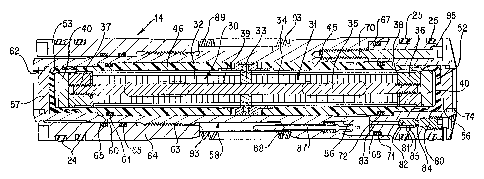
As shown in Figure 2, the opposite end portions
20, 21 of the transmitter 14 are received in diametrically
opposed openings or holes 22, 23 that extend through the
walls of the collar 13. Seal rings 24, 25 on the portions
20, 21 engage the walls of the openings 22, 23 to prevent
fluid leakage from inside collar 13 to the annulus within
borehole 10. The diameters of the openings 22, 23 are
identical so that there are no unbalanced lateral forces on
the transmitter 14 due to pressure differences inside and
outside the collar 13 during drilling. The transmitter 14
is mounted inside a spider or flow diverter assembly 26 that
is fixed within the bore 27 of the collar 13, diverter
assembly 26 providing flow passages and ports for electrical
wiring and connector components which need not be described
since they form no part of the present invention. The
diverter 26 also forms a pair of oppositely facing, annular
shoulders 90 and 91 which cooperate in the mounting of the
transmitter 14 as will be described in detail below.
As shown in further detail in Figure 3, the
transmitter assembly 14 includes oppositely extending stacks
30, 31 having equal numbers of washer-shaped piezoelectric
crystals 32 and a nodal plate 33 between the inner ends of
such stacks. Each piezoelectric crystal 32 is silver-coated
on its two faces and has a built-in electrical polarization.
Because of this, one face is
5b
~1~~~Q'~
denoted positive (+) while the other is denoted negative (-), and a positive
voltage from the
negative (-) to the positive (+) face causes the crystal thickness to
increase. This is the
piezoelectric effect
The placement of the piezoelectric crystals 32 in each stack 30, 31 with
respect to their
polarizations is shown in Figure 4. In each stack 30, 31, the innermost
crystal faces abutting
the nodal plate 33 are positive. Proceeding away from the center, the next
crystal 32 has a
negative face facing inward and abutting the negative face of the innermost
crystal 32. Thus the
crystals 32 are arranged in each stack 30, 31, so that the faces of adjacent
crystals have the same
polarity. Thin metal electrodes 34 are mounted between adjacent faces of the
crystals 32.
Referring again to Figure 3, the stacks 30, 31 are held together under
compression by
a central rod 35 whose opposite ends are threaded to nuts 36, 37. An insulator
38 is positioned
between each nut and the outermost electrode 34. Additionally, a thin
cylindrical insulator 39
is fitted over the central rod 35 inside stacks 30, 31. As shown in better
detail in Figure 5, the
nodal plate 33 has an outwardly directed flange 41, and insulating sleeves 42,
43 are positioned
on opposite sides of the flange 41. An insulating ring or band 44 surrounds
the flange 41 and
a portion of each sleeve 42, 43 and, with the aforementioned insulators,
serves to protect against
short circuits and arcing.
All the electrodes 34 between the positive faces of the crystals 32 are
connected together
by a single bus bar 98 forming a positive terminal as shown schematically in
Figure 4.
Similarly, all the electrodes 34 between the negative faces of the crystals 32
are connected
together by another single bus bar 99 forming a negative terminal. This
arrangement allows the
6
~~.r~3~~~~
piezoelectric effect of the crystals 32 to be coordinated for maximum motion.
When the
terminals are connected to an alternating voltage generator (not shown), the
stacks 30, 31 expand
and contract in unison generating pressure waves in the surrounding medium. It
should be noted
that the motion of the combined stacks 30, 31 is similar to the lowest order
of a half wave
resonator that is free at the ends. This motion has a maximum amplitude at the
ends (nuts 36,
37), has a null at the center (nodal plate 33), and is symmetric about the
center.
The above-described crystal assembly is mounted within a pair of carrier
sleeves 45, 46
which preferably are made of relatively soft plastic material. The inner
portion 47 (Figure 5)
of each carrier sleeve 45, 46 has an enlarged inner diameter so that it slips
over the skirt 48 of
insulating sleeve 42, 43, and the end face of each carrier sleeve 45, 46
terminates short of the
enlarged diameter portion 50 of each insulating sleeve 42, 43. A spring such
as an undulating
or wavy washer 51 is fitted in each of the gaps between the portions 50 and
the end faces of the
insulating sleeves 42, 43. Diametrically opposed slots (not shown) are formed
in the nodal plate
33 for the passage of bus bars 98, 99 by which voltages are applied to the
crystal electrodes 34.
The outer ends of the carrier sleeves 45, 46 are closed by compliant caps 52,
53 which can be
made of rubber or a rubber-like substance. Barrier discs 56, 57 are loosely
mounted at the outer
ends of the carrier sleeves 45, 46. Floating discs 40 are positioned inside
caps 52, 53 adjacent
nuts 36, 37.
The components thus far described are mounted or contained within a tubular
housing,
indicated generally at 58, which is filled with oil. The housing 58 has an
internal shoulder 60
that engages an external shoulder on the carrier sleeve 46. A seal ring 61
prevents leakage of
7
the oil surrounding stacks 30, 31. An inwardly extending flange 62 on the
outer end of the
housing 58 retains the barrier disc 57 in place. The housing 58 has external
threads 63 that
mesh with companion threads on a mounting sleeve 64, and internal seal rings
65 are provided
to prevent infiltration of the drilling mud into the electrical connections of
transmitter 14. The
external seal rings 24 on mounting sleeve 64 engage inner wall surfaces of the
opening 22 in the
drill collar 13 when the transmitter 14 is in place as shown in Figure 2.
The other end of the housing 58 is provided with an annular seat 67 that
receives the
reduced diameter inner end portion of a head 68. The head 68 is held in the
seat 67 by several
cap screws 70 which extend into threaded bores in the housing 58. Each cap
screw 70 has a seal
ring 95 to prevent oil leakage from transmitter 14. A seal ring 71 prevents
oil leakage between
the head 68 and the seat 67, and another seal ring 72 prevents oil leakage
between the head 68
and the carrier sleeve 45. External seal rings 25 engage the walls of the
opening 23 in the drill
collar 13. The head 68 has an inwardly extending flange 74 to retain the
barrier disc 56.
An oil filling valve element 80 is threaded into a bore 81 in the head 68 and
has an end
portion 82 which seats against a surface which surrounds the outer end of a
passageway 83
which opens into the interior of the transmitter assembly 14. The valve
element 80 also carries
a seal ring 84. A transverse port 85 extends from the valve seating area to
the outside of the
head 68. When the valve 80 is moved outwardly by turning the same, procedures
are used to
evacuate the interior spaces of the transmitter assembly 14 and then to fill
such spaces with a
non-conductive oil. The oil in the interior of transmitter 14 efficiently
couples the motion of the
nuts 36, 37 to the exterior of the caps 52, 53 and through barrier discs 56,
57 to set up pressure
8
~~.~~~fl°~
waves in the borehole 10. Note that in this coupling the caps 52, 53, the
floating discs 40; and
the barrier discs 56, 57 have very little acoustic attenuation or effect. The
compliant caps, 52,
53, via their expansion and contraction, also compensate for changes in the
oil volume with
temperature and pressure.
A cavity 86 is formed in the outer end of the head 68 into which electrical
feed-through
assemblies 87 extend so that conductor wires (not shown) can couple the bus
bars 98, 99 to the
external voltage generator (not shown) by which the crystals 32 are excited.
Resilient elements,
preferably bellville washer sets 88 and 89, are positioned between the
shoulders 93 which are
formed on the inner end faces of the mounting sleeve 64 and the housing 58,
and the shoulders
90 and 91 (Fig. 2) on the flow diverter 26. As will appear below, the wavy
washers 51, the
carrier sleeves 45, 46 and the bellville washers 88, 89 constitute parts of
spring-mass systems
which attenuate transmission of sonic waves to the drill collar 13.
OPERATION
In operation, the transmitter assembly 14 is assembled as shown in the
drawings, except
for the mounting sleeve 64 and the left side bellville washers 89, and then
loaded into the collar
13 through the hole 23. Then the left side washers 89 and the mounting sleeve
64 are installed
through the opposite hole 22 and the threads 63 are made up. The various
electrical connections
also are made up by means of a connector block that engages feed-through
assemblies 87. It
should be noted that the entire transmitter system has bilateral symmetry
about the longitudinal
axis of the collar l3,which is an additional feature of the present invention.
The sonic collar 13
is connected into the drill string 12 which then is lowered into the borehole
10. As the borehole
9
~~v~~~~
is deepened by the bit 11, a sonic log is obtained by pulsing a voltage
generator connected
to transmitter 14 and detecting the arrival of sonic waves that have traveled
upward through the
formation into the spaced receivers 15 and 16 as shown in Figure 1. The use of
spaced receivers
is preferred to eliminate travel time in the mud and the effect of borehole
diameter on the
measurements. As noted above, more porous formations have a lower sound
velocity.
When a positive voltage is applied across the terminals to the crystal stacks
30, 31 they
both expand about the nodal plate 33, causing pressure waves to radiate
outward at each end.
When a negative voltage is applied, the stacks 30, 31 contract about the nodal
plate 33 in
preparation for the next expansion. Since the composite stack of crystals is
held at its center on
the nodal plate 33 where motion is at a minimum, motion imparted to the
container assembly
from the stack is minimized. Such nodal plate support thus is an important
feature of the present
invention.
The nodal plate 33 is held in the housing 58 by wavy washers 51 and by the
long, thin
high temperature plastic carrier sleeves 45, 46. The wavy washers 51, together
with the mass
of the stacks 30, 31 and the carrier sleeves 45, 46 form a spring-mass
isolator system in which
the stack and sleeve masses resonate with the springs. However, the wavy
washers 51 are
compliant enough so that the isolator resonance is much lower than the
operating frequency of
the transmitter 14, and there is significant attenuation at such operating
frequency. Thus if there
is some residual motion of the nodal plate 33 at the operating frequency, it
will be attenuated as
it is transferred to the housing 58.
The springs 88, which as noted above are bellville washers, hold the housing
58 assembly
in the collar 13. The threaded mounting sleeve 64 allows the housing 58 to be
inserted into the
collar 13 while being held with equal force on both ends. Thus, any residual
vibration coupled
into collar 13 will be symmetric and equal at shoulders 90, 91. The housing 58
also is isolated
from the collar 13 by the springs 88. Again, the design is such that the
resonance or natural
frequency of the springs 88 plus the transmitter assembly 14 is much lower
than the operating
frequency of the transmitter, so that residual motion transmitted from the
housing 58 to the flow
diverter 26 and the collar 13 is attenuated. Indeed, the springs 88 are a
primary means to
prevent the sonic energy from coupling into the collar 13.
The transverse cross-sectional areas bounded by the seal rings 24, 25 on the
mounting
sleeve 64 and the head 68 are equal, so that pressure forces on the
transmitter 14 are always
balanced. Thus the only force holding the transmitter 14 in the collar 13 is
due to the springs
88. This means that the spring isolator formed by springs 88 is maintained,
regardless of well
depth, and is independent thereof. The mounting forces are constant with
depth, and are
symmetric so as to minimize the generation of asymmetric vibrations. Thus any
collar arrivals
should be independent of depth.
The sonic transmitter 14 of the present invention also has bilateral symmetry
in that the
stacks 30, 31, the carrier sleeves 45, 46, the components of the housing 58,
and the collar
around it are symmetric about the nodal plate 33. The retention point for the
nodal plate 33 is
constrained by the geometry of the carrier sleeves 45, 46, the housing
assembly 58, the wavy
washers 51 and the bellville washers 88 so that the stacks 30, 31 axe centered
transversely in the
collar 13. This arrangement makes the acoustic loading and coupling of any
motion as
11
symmetric as possible. Thus any residual motion imparted from the stacks 30,
31 to the housing
58 and to the collar 13 will be primarily symmetric. This minimizes the
generation of
asymmetric collar arrivals.
It will be recognized that a new and improved sonic transmitter for use in LWD
has been
disclosed. The coupling of motion into the drill collar is minimized,
particularly asymmetric
motion. Thus the detection of arrivals of sonic waves that have traveled
through the formation
is enhanced. Since certain changes or modifications may be made in the
disclosed embodiment
without departing from the inventive concepts involved, it is the aim of the
appended claims to
cover all such changes and modifications falling within the true spirit and
scope of the present
invention.
12