Language selection

Search

Patent 2139202 Summary

Third-party information liability

Some of the information on this Web page has been provided by external sources. The Government of Canada is not responsible for the accuracy, reliability or currency of the information supplied by external sources. Users wishing to rely upon this information should consult directly with the source of the information. Content provided by external sources is not subject to official languages, privacy and accessibility requirements.

Claims and Abstract availability

Any discrepancies in the text and image of the Claims and Abstract are due to differing posting times. Text of the Claims and Abstract are posted:

  • At the time the application is open to public inspection;
  • At the time of issue of the patent (grant).
(12) Patent: (11) CA 2139202
(54) English Title: NOISE REMOVING APPARATUS USING A MICROPHONE
(54) French Title: APPAREIL ELIMINATEUR DE BRUIT UTILISANT UN MICROPHONE
Status: Expired and beyond the Period of Reversal
Bibliographic Data
(51) International Patent Classification (IPC):
  • G10K 11/16 (2006.01)
  • H04M 01/03 (2006.01)
  • H04M 01/19 (2006.01)
  • H04R 01/22 (2006.01)
  • H04R 03/02 (2006.01)
(72) Inventors :
  • YOSHIDA, TOSHIO (Japan)
  • SISIDO, MICHITAKA (Japan)
(73) Owners :
  • NEC CORPORATION
(71) Applicants :
  • NEC CORPORATION (Japan)
(74) Agent: SMART & BIGGAR LP
(74) Associate agent:
(45) Issued: 1999-02-02
(22) Filed Date: 1994-12-28
(41) Open to Public Inspection: 1995-06-29
Examination requested: 1994-12-28
Availability of licence: N/A
Dedicated to the Public: N/A
(25) Language of filing: English

Patent Cooperation Treaty (PCT): No

(30) Application Priority Data:
Application No. Country/Territory Date
338494/1993 (Japan) 1993-12-28

Abstracts

English Abstract


An arrangement for noise removal according to the
present invention includes a microphone and an acoustic
high-pass filter positioned in front of the microphone
and consisting of the combination of an acoustic
resistance, an acoustic compliance and an inertance.
According to the invention, the acoustic resistance is
composed of nonwoven fabric; the acoustic compliance,
of a cavity; and the inertance, of a thin cavity connected
to said cavity. This acoustic high-pass filter reduces
unpleasant noise which arises from the microphone when
a low-frequency high-pressure air stream, such as the
speaker's breath, hits the mouthpiece of the telephone.


French Abstract

Dispositif de suppression de bruit, comprenant un microphone et un filtre acoustique passe-haut placé devant le microphone. Le filtre combine un élément de résistance acoustique, un élément d'élasticité acoustique et un élément d'inertance, composés respectivement de non-tissé; d'une cavité assurant l'élasticité acoustique; et d'une cavité mince reliée à la première cavité. Il réduit le bruit désagréable que produit le microphone lorsqu'un jet d'air de basse fréquence sous haute pression, dû p. ex. au souffle du locuteur, frappe l'embouchure du téléphone.

Claims

Note: Claims are shown in the official language in which they were submitted.

THE EMBODIMENTS OF THE INVENTION IN WHICH AN EXCLUSIVE
PROPERTY OR PRIVILEGE IS CLAIMED ARE DEFINED AS FOLLOWS:
1. An arrangement for noise removal comprising:
a microphone;
an acoustic filter positioned in front of said
microphone;
wherein said filter includes:
at least one sound input hole bored in the casing of an
electronic apparatus to constitute an acoustic inertance;
a filter body, installed within said casing, having at
least one cavity continuous to said at least one holes to
constitute at least one acoustic compliance and a holding hole
for keeping said microphone; and
a member arranged in front of said microphone to
constitute an acoustic resistance.
2. An arrangement, as claimed in Claim 1, wherein said
member is a net.
3. An arrangement, as claimed in Claim 1, wherein said
filter body is made of rubber.
4. An arrangement, as claimed in Claim 1, wherein the
number of said speech input holes is two.

5. An arrangement, as claimed in Claim 1, wherein said
filter body has a convexly shaped cross section.

Description

Note: Descriptions are shown in the official language in which they were submitted.


2139202
NOISE REMOVING APPARATUS USING A MICROPHONE
BACKGROUND OF THE INVENTION
The present invention relate~ to a noise removing
apparatus, and more particularly to a noise removlng
apparatus using a microphone.
A typical noise removlng apparatus according to the
related art is disclosed in the Japanese Patent Laid-open
No. 247498 of 1992. The conventional nolse removing
apparatus i~ provided with a first microphone lnto which
speech signals are entered and a second microphone into
which ambient nolse ls entered. Noise }8 removed by
subtracting the ambient noise entered into the second
microphone from the ambient noise-containing speech
signals entered into the first microphone.
Howe~er, it is difficult for such a noise removing
apparatus to cancel locally generating noise such as a
low-frequency high-pre~sure air stream, e.g. the speaker' 5
breath, because the noise signal enters into only one of
the microphones. Furthermore, since the two microphones
have to be positioned at some distance from each other,
this arrangement is hardly applicable to a p~rtable
system, such as a portable telephone, in which the
available sDace is narro~l~ l$mited.
91 ,'t d 066960; 0~ ~X~' l t-: 611~t~ 0Z ( ~) E3gZ~Z l~t~66 1 :~N 'NO l S I l~ l a 'd ' I YIOY.~

2139202
-- 2
SUMMARY OF THE 1N V~N 1 ION
An object of the present invention is to obviate the
aforementioned disadvantages and provide an arrangement
for noise removal, which is capable of reliably removing
noi~e including low-frequency high-pressure air streams.
An arrangement for noise removal accordin~ to the
invention is provided with a hole for the ~peech input,
bored in the casing of the telephone set to constitute
an acoustic lnertance, and a filter body installed within
1~ the casing. This filter body has a cavity, continuous
to the speech input hole, constltuting an acoustic
compllance, and a holding hole for ho~ding a microphone.
In the holding hole is kept the microphone, and ln front
of the microphone is arranged a member constituting an
acoustic re~istance.
BRIEF DESCRIPTION OF THE DR~WINGS
The above-mentioned and other object~, features
and advantages o~ the pre~ent invention will become more
~pparent from the following aetailed description when
taken in conjunction with the accompanying drawlngs,
wherein:
FIG5. lA through lE and FIGS. 2A through 2E are
diasrams for explaining the principle of the noise
removing apparatu~ according to the invention;
FIGS. 3A and 3~ show respectively a plane view of
91/S d 066360tOS~:~Xlt, :6tl~Vb~:OZ (13') G9Z~Zl~b66t ~3N 'No181AI~1 d ~1 ~o'd t

213s2n2
-- 3 --
one preferred embodlment of the invention and a cross-
sectional view thereof; and
FIGS. 4A and 4B show respectively a plane view of
another preferred embodiment of the invent$on and a
cross-sectional view thereof.
DETAILED DESCRIPTION OF THE PREFERRED EM~ODIMENTS
Fir~t will be explalned the prlnciples of the present
invention with reference to FIGS. lA through lE and
FIGS. 2A through 2~.
lG Accord~ng to the inYention, the mouthpiece is so
configured as to constitute an acous~o-structural filter
serving as a noise remo~ing apparatus and to reduce the
noise content of ~ignals. This filter basically includes
the combination of a microphone and what may become
necessary out of three constituent unit~ arranged upstream
of the microphone. The three constituent unlts are an
aco~tstic resistance rA, an acoustic compllance CA and an
inertance mA. Structurally, the acoustic resistance rA
can be composed of nonwoven fabric (net~ to attenuate
sound. The acoustic compliance CA can be composed of a
pipe having an opening at one end and having no conctricted
part, and the inertance mA, of a pipe having an opening at
each end and havlng no constricted part. The right-hand
side of a mlcrophone 1 is the $nput section (diaphxagm),
and speech i~ entered from the right-hand side of the
drawings.
gi~9 d 066g50tO'i~~:1~/lt:611~ib~:0Z 1~) 13gZ!~Zl*b661 :~ tN NOISIAICt d I ~Oti t

2139202
.
-- 4
Referring to FIG. lA, the microphone 1 is arranged at
one end of a metallic or plastic p~pe 20 havlng an openlng
at each end. In this configuration, as one end of the
pipe 20 is blocked ~y the microphone 1, the other end ~f
this pipe 20 is open to constitute an acoustic compli~nce
~hereina~ter simply referred to a~ "compliance") CA. The
~alue o~ the compliance CA 1~ determined by the length and
bore of the pipe among other factors. Referring further
to ~IG. lA, a piece of nonwoven fabric 21 is arranged in
front of the microphone 1 to constitute an acoustic
resistance rA, whose value ra is determined by the volume
and material of the nonwoven fabric piece 21 among other
factors. An electrically equivalent circult having such
a structure, as illustrated in FIG. 2A, es expressed as
a high-p2ss filter ~HPF) having a resistor 21A and a
capacitor 2OA.
In the structure shown in FIG. 1~, a second nonw~oven
fabric piece 22, separately from the first nonwoven fabrlc
pie~e 21, ls arranged in the intermed'ate part of the
pipe 20 of FIG. lA, and two co~pliances CAl and CA2 are
there~y formed in the plpe 20. The electrlc circult here,
as shown in FIG. 2Bj is expressed as an HPF having two
resistors 21A and 22A and two capacitors 20Al and 20A2.
On the other hand, ln the structure of FIG. lC, a
pip~ section 24 having an openlng at each end is formed
in the intermedlate part of the pipe of FIG. lA. This
d G6696QlC~ 611~f~ 0Z (~) agZ~Z1~$~661 .'):IIN 'N01:31AIa d I ~O'd~

2139202
- 5 -
pipe section 24 constitutes an inertance ma, which, as
illustrated in FIG. 2C, is expressed as an inductance 24A
in an equivalent circuit. FIG. 2C also shows an HPP.
FIGS. lD and lE, as described above, also illustrate
the realization of a compliance CA, a resistance ra and
~n inert~nce ma by the combination of a pipe and nonwoven
fabric, and accordingly their detailed description is
di~pensed with.
~ lectrically equlvalent clrcults in these cases are
lG shown in FI~S. 2~ and 2E, respectively. Incidentally,
FIG. 2D illustrates a band-pass fllter (BPF~, and FIG. 2E,
an HPF.
Thus it is to be understood that a resistor, a
capacitor and an inductance to constitute an electric
filter can be acoustically re~lized by the combination
of a pipe and nonwoven fabric.
Next, filters according to the lnvention, embodying
the above-explained princlple, will be described with
reference to FIGS. 3 and 4. Although the embodiments
to be descri~ed b~low are portable telephones u&ing a
condenser microphone each, the applicabillty of the
inventlon ls not limlted to it. In each embodiment,
the input section of the microphone 1 i~ at the bottom
end of the diagram, and speech signals are entered fro~
outside the telephone casing via an inertance mA.
In the first preferred embodiment illustrated ln
91/8 d ~6696C!058~ 61~t/9~ 0Z(~)99Z~Zl~b661 ~N '~OISIAIC 'd I AO~

2139202
FIGS. 3A and 3B, a rubber-built filter body 2 is fitted
with adheslve to the inside of the front plate 4 of the
casing. The front plate 4 has a speech input hole to
const$tute the inertance mA. The filter body 2 has a
S cavity, conneGted to the speech lnput hole, to constitute
the acoustic compliance CA and a hole 6 ~or supporting and
holding the mlcrophone 1. The microphone 1 is fixed to
the hole 6 with, e.g., a~hesive. Aelow the microphone 1
i6 arranged a nonwoven fabric net to constitute an acoustic
resistance rA. As ls evldent from FIG. 3, an electrically
equivalçnt circuit to the first embodiment ls represented
in FIG. 2D, which illustrates an HPF, and removes low-
freguency nolse.
Referring now to FIGS. 4A and 4B, a second preferred
embodiment of the present in~ention has a rubber-built
filter body 5 having a convexly shaped cross section,
fitted to the inside of the front plate 4 of the telephone
casing. The front plate 4, unlike that of the first
embodiment, has two holes to con~titute two lnertances
mAl and mA2. The filter body 5 has cavities, connected
to these inertances mAl and mA2, to constitute two acoustic
compliances CAl and CA2. The filter body 5 f~rther has
in its upper part a holding hole for housing the micro-
phone 1. Below the microphone 1 ls arranged a piece of
nonwoven fabric to constltute an acou~tic reslstance rA.
An electrically equivalent circuit to this second
91/6 d 066~60105~!5~.~ 6il~/5~ :0Z IY) ~39Z~ZI~1'661 O~N '~OISIAI(I d ~l nO~II

2139202
embodiment is represented ~y ,~ circuit in which inductances
l and ~A2 are connected in series to the capa~itors
CA1 and CA2, respectively, of FIG. 2D. The second
embodlment, like the first embodiment, can suppress
low-frequency noise.
As hitherto described, the present invention makes
it possible, even if such a low-frequency high-pressure
air stream as an extern,~l w~nd or the ~peaker's breath
hits ~he mouthpiece of a capacitor microphone of an
appara~us frequency used outdoors, such as a portable
telephone, to selectlvely reduce unpleasant noise
resulting from this air stream without siqnificantly
: bringin~ down the speech level.
gl~01 d 066960105~~'1t7:61~/~ Oc, ~ ZI~Z 1:~6~1 O~IN 'NOISIA ia d I ~'IO'di

Representative Drawing
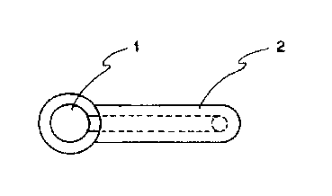
A single figure which represents the drawing illustrating the invention.
Administrative Status

2024-08-01:As part of the Next Generation Patents (NGP) transition, the Canadian Patents Database (CPD) now contains a more detailed Event History, which replicates the Event Log of our new back-office solution.

Please note that "Inactive:" events refers to events no longer in use in our new back-office solution.

For a clearer understanding of the status of the application/patent presented on this page, the site Disclaimer , as well as the definitions for Patent , Event History , Maintenance Fee  and Payment History  should be consulted.

Event History

Description Date
Inactive: IPC from MCD 2006-03-11
Time Limit for Reversal Expired 2002-12-30
Letter Sent 2001-12-28
Grant by Issuance 1999-02-02
Inactive: Final fee received 1998-11-09
Pre-grant 1998-11-09
Inactive: Received pages at allowance 1998-11-09
Notice of Allowance is Issued 1998-05-12
Letter Sent 1998-05-12
Inactive: Status info is complete as of Log entry date 1998-05-04
Inactive: Application prosecuted on TS as of Log entry date 1998-05-04
Inactive: IPC assigned 1998-03-23
Inactive: IPC removed 1998-03-23
Inactive: First IPC assigned 1998-03-23
Inactive: Approved for allowance (AFA) 1998-03-20
Application Published (Open to Public Inspection) 1995-06-29
All Requirements for Examination Determined Compliant 1994-12-28
Request for Examination Requirements Determined Compliant 1994-12-28

Abandonment History

There is no abandonment history.

Maintenance Fee

The last payment was received on 1998-11-16

Note : If the full payment has not been received on or before the date indicated, a further fee may be required which may be one of the following

  • the reinstatement fee;
  • the late payment fee; or
  • additional fee to reverse deemed expiry.

Patent fees are adjusted on the 1st of January every year. The amounts above are the current amounts if received by December 31 of the current year.
Please refer to the CIPO Patent Fees web page to see all current fee amounts.

Fee History

Fee Type Anniversary Year Due Date Paid Date
MF (application, 3rd anniv.) - standard 03 1997-12-29 1997-11-18
Final fee - standard 1998-11-09
MF (application, 4th anniv.) - standard 04 1998-12-29 1998-11-16
MF (patent, 5th anniv.) - standard 1999-12-28 1999-11-15
MF (patent, 6th anniv.) - standard 2000-12-28 2000-11-16
Owners on Record

Note: Records showing the ownership history in alphabetical order.

Current Owners on Record
NEC CORPORATION
Past Owners on Record
MICHITAKA SISIDO
TOSHIO YOSHIDA
Past Owners that do not appear in the "Owners on Record" listing will appear in other documentation within the application.
Documents

To view selected files, please enter reCAPTCHA code :


To view images, click a link in the Document Description column (Temporarily unavailable). To download the documents, select one or more checkboxes in the first column and then click the "Download Selected in PDF format (Zip Archive)" or the "Download Selected as Single PDF" button.

List of published and non-published patent-specific documents on the CPD .

If you have any difficulty accessing content, you can call the Client Service Centre at 1-866-997-1936 or send them an e-mail at CIPO Client Service Centre.

({010=All Documents, 020=As Filed, 030=As Open to Public Inspection, 040=At Issuance, 050=Examination, 060=Incoming Correspondence, 070=Miscellaneous, 080=Outgoing Correspondence, 090=Payment})


Document
Description 
Date
(yyyy-mm-dd) 
Number of pages   Size of Image (KB) 
Abstract 1995-06-28 1 18
Description 1995-06-28 7 214
Claims 1995-06-28 2 40
Drawings 1995-06-28 3 65
Claims 1998-02-24 2 32
Drawings 1998-11-08 3 43
Representative drawing 1998-06-09 1 5
Representative drawing 1999-01-26 1 2
Commissioner's Notice - Application Found Allowable 1998-05-11 1 164
Maintenance Fee Notice 2002-01-27 1 179
Correspondence 1998-05-11 1 99
Correspondence 1998-11-08 4 103
Fees 1996-11-19 1 89
Prosecution correspondence 1994-12-27 115 330
Prosecution correspondence 1997-10-19 2 52
Examiner Requisition 1997-06-19 2 42
Prosecution correspondence 1997-11-11 1 29
Prosecution correspondence 1997-12-17 1 18
Prosecution correspondence 1997-11-11 4 130