Language selection

Search

Patent 2139215 Summary

Third-party information liability

Some of the information on this Web page has been provided by external sources. The Government of Canada is not responsible for the accuracy, reliability or currency of the information supplied by external sources. Users wishing to rely upon this information should consult directly with the source of the information. Content provided by external sources is not subject to official languages, privacy and accessibility requirements.

Claims and Abstract availability

Any discrepancies in the text and image of the Claims and Abstract are due to differing posting times. Text of the Claims and Abstract are posted:

  • At the time the application is open to public inspection;
  • At the time of issue of the patent (grant).
(12) Patent Application: (11) CA 2139215
(54) English Title: VEHICLE GLASS RUN CHANNEL WITH CORNER INSERT
(54) French Title: PUITS DE GLACE DE VEHICULE, MUNI D'UN ELEMENT RAPPORTE D'ANGLE
Status: Deemed Abandoned and Beyond the Period of Reinstatement - Pending Response to Notice of Disregarded Communication
Bibliographic Data
(51) International Patent Classification (IPC):
  • B60J 10/76 (2016.01)
  • B60J 10/21 (2016.01)
  • B60J 10/23 (2016.01)
  • B60J 10/80 (2016.01)
(72) Inventors :
  • MESNEL, GERARD (France)
(73) Owners :
  • THE STANDARD PRODUCTS COMPANY
  • COOPER-STANDARD AUTOMOTIVE INC.
(71) Applicants :
  • THE STANDARD PRODUCTS COMPANY (United States of America)
  • COOPER-STANDARD AUTOMOTIVE INC. (United States of America)
(74) Agent: MACRAE & CO.
(74) Associate agent:
(45) Issued:
(22) Filed Date: 1994-12-28
(41) Open to Public Inspection: 1995-07-22
Examination requested: 2001-12-24
Availability of licence: N/A
Dedicated to the Public: N/A
(25) Language of filing: English

Patent Cooperation Treaty (PCT): No

(30) Application Priority Data:
Application No. Country/Territory Date
184,473 (United States of America) 1994-01-21

Abstracts

English Abstract


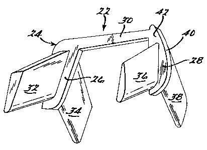
A vehicle glass run channel comprises a pair of elongated members
which are joined in a mitered corner at the intersection of the vehicle door
header and vertical pillar. The elongated members are secured together and
reinforced by a corner insert. The corner insert has a generally U-shaped
body providing an inner and outer leg joined by a web. Generally horizontally
extending inner and outer wings extend respectively from the inner and outer
leg and generally vertically disposed inner and outer wings extend
respectively from the inner and outer legs. The wings slidably fit within
corresponding internal (channels) formed in legs of the glass run header
channel and glass run vertical channel.


Claims

Note: Claims are shown in the official language in which they were submitted.


-5-
What is claimed is:
1. A glass run channel for a vehicle, the glass run channel having:
(A) an elongated header glass run member;
(B) an elongated pillar glass run member; and
(C) a corner insert;
each said header member and pillar member having a generally U-
shaped channel for receiving an edge of an associated glass pane, each said
channel having a leg comprised of elastomeric material and having a pocket
therein, said header member and said pillar member having mitered ends
joined at a corner by said corner insert positioned therebetween and secured
thereto, said insert having a generally U-shape with legs joined by a web,
each leg having a wing extending outwardly therefrom into an associated
pocket and being fixedly secured therein.
2. A glass run channel as in claim 2 wherein said insert has an
outer leg having a surface exposed to view and a pair of opposing surfaces,
each in contacting relationship with an associated end surface of one of said
header member and said pillar member.
3. A glass run channel as in claim 3 wherein each of said wings is
tapered.
4. A glass run channel as in claim 4 wherein each said wing is
secured within an associated pocket by elastomeric material.
5. A glass run channel as in claim 4 wherein each said wing is
secured within an associate pocket by press fit.
6. A glass run channel as in claim 5 wherein each said member
has a metal core with an elastomeric skin.

- 6 -
7. A glass run channel as in claim 2 wherein said wings are in
pairs, each wing extending generally perpendicular to another wing.

Description

Note: Descriptions are shown in the official language in which they were submitted.


2139215
-
v
VEHICLE GLASS RUN CHANNEL WITH CORNER INSERT
Background of the Invention
The present invention relates to glass run channel for automotive
5 vehicles and, more particularly, to a vehicle glass run channel having a corner
insert.
Vehicle glass run channel is used in automotive vehicles and the like
to movably support window panes which have translational movement
between an open and closed position. The glass run channel guides and
10 supports the window pane and forms a seal around the perimeter of the
window pane to protect the passenger compartment from the weather
elements.
Glass run channel must be structurally sound and while also allowing
translational movement of the window pane with~ut undue resistance.
15 Automotive window openings are often designed to have a shape which
poses a challenge to the design and manufacture of a glass run channel
which extends around the necessary periphery of the window opening and yet
meet the above requirements. In particular, the corner structure of glass run
channel is problematic with respect to structural integrity and visual
20 appearance.
In accordance with the present invention, a glass run channel is
provided for an automotive vehicle which has an improved corner insert. The
glass run channel is structurally sound and has a pleasing visual appearance
particularly in the traditionally difficult corner area. Furthermore, the corner25 insert facilitates improved accuracy in manufacture of the length of glass run
channel.
Further understanding of the invention will be had from the
accompanying drawings and following specification.

21 392 1~
-
- 2 -
Summary of the Invention
In accordance with the present invention, a vehicle glass run channel
comprises a pair of elongated members which are joined in a mitered corner
at the intersection of the vehicle door header and vertical pillar. The
5 elongated members are secured together and reinforced by a corner insert.
The corner insert has a generally U-shaped body providing an inner and outer
leg joined by a web. Generally horizontally extending inner and outer wings
extend respectively from the inner and outer leg and generally vertically
disposed inner and outer wings extend respectively from the inner and outer
10 legs. The wings closely fit within corresponding pockets formed in legs of the
glass run header channel and glass run vertical channel.
Brief Description of the Drawings
Figure 1 is a partial elevational view of a vehicle showing a preferred
15 embodiment of a vehicle class run channel with corner insert of the present
invention.
Figure 2 is an enlarged perspective view of a preferred embodiment of
a corner insert of the present invention.
Figure 3 is a partial exploded elevational view showing the corner
20 insert of Figure 2 in relationship to associated horizontal header glass run and
pillar glass run members.
Figure 4 is a partial elevational view showing the vehicle glass run
channel with corner insert of Figure 1.
Figure 5 is a sectional view taken along line 5-5 in Figure 1.
Description of the Preferred Embodiment
Now referring to the figures, a preferred embodiment of the glass run
channel with corner insert of the present invention is illustrated in Figure 1
and indicated by the numeral 10. Glass run channel 10 is shown installed on
30 door 12 of automobile 14 and is in operative association with window pane
16 which is vertically translational between open and closed positions as is
conventional in modern automotive vehicles.

213g21~
-
- 3 -
Broadly speaking, glass run channel 10 comprises a header 18 and a
pillar 20 which are joined in a mitered corner at the intersection of the vehicle
door header and vertical pillar with insert 22.
Insert 22 has a generally U-shaped body 24 with inner leg 26 and outer
5 leg 28 joined by web 30. The terms "inner" and "outer" as used herein are
with reference to the interior and exterior of automotive vehicle 14. Extending
outwardly from inner leg 26 and generally at a right angle with respect to
each other are inner header wing 32 and inner pillar wing 34. Extending
outwardly from outer leg 28 generally at a right angle with respect to each
10 other are outer header wing 36 and outer pillar wing 38. Outer leg 28 has a
show surface 40 which is presented to view exterior of the automotive
vehicle. Body 24 of insert 22 has a thin width, on the order of 2mm, so that
show surface 40 is presented as a thin clean line to an observer. U-shaped
body 24 has side surfaces 42 and 44 which abut against mitered ends 46 and
15 ~8 of respective header 18 and pillar 20. This allows accurate sizing of the
lengths of header 18 and pillar 20.
As is best shown in Figure 5, header 18 includes a metallic reinforcing
core 50. Core 50 may be a solid metal core as illustrated in the figure or
optionally may be formed from flexible wire, lanced or perforated metal core
20 or even suitable polymeric material. Core 50 is formed into a generally S-
shape thereby providing a U-shaped channel portion 52 to attach to flange
54. Core 50 also has a U-shaped glass run channel portion 56 which
receives edge 58 of glass pane 16. U-shaped channel portion 52 and U-
shaped glass run channel portion 56 share a common leg 60. An elastomeric
skin 62 covers core 50 and has polymeric retention ribs 64 within U-shaped
channel portion 52 and glass guiding and sealing members 66 and 68 within
U-shaped glass run channel portion 56 and also has sealing ribs 70, 72 and
74 extending from elastomeric skin 62 to provide a weather seal with respect
to door 12.
U-shaped glass run channel portion 56 of core 50 has common leg 60
and outer leg 76 joined by web 78. Elastomeric skin 62 has a portion 78
associated with leg 60 and a portion 80 associated with leg 76. Elastomeric

2139215
-
- 4 -
skin leg 78 has a pocket 82 therein while elastomeric leg 80 has a pocket 84
therein. Pocket 82 is selectively sized to tightly receive inner header wing 32
while pocket 84 is selectively sized to tightly receive outer header wing 36 of
insert 22.
Generally vertically extending pillar 20 is of cross-sectional shape
analogous to header 18 as shown in Figure 5 with corresponding pockets in
the elastomeric skin to receive inner pillar wing 34 and outer pillar wing 38 ofinsert 22.
In the manufacture of glass run channel 10, header 18 and pillar 20 are
extruded and miter cut to length as is conventional in the art. Then, insert 22
is joined to the mitered ends of header 18 and pillar 20. In a rubber mold,
wings 32, 34 are inserted into associated pockets in header 18 and pillar 20
and wings 36 and 38 are inserted into associated pockets in header 18 and
pillar 20. Surfaces 46 and 48 of header 18 and pillar 20 are brought into
abutting relationship with facing surfaces 42 and 44 of insert 22. The
accuracy of the length of header 18 and pillar 20 is not affected by the
molding process. This allows accurate sizing of the length of each of header
18 and pillar 20. Then rubber is injected into the cavity around insert 22
proximate to web 30 to bond the corner structure.
While the above description describes a preferred embodiment of the
present invention, it will be understood that the present invention is
susceptible to modification, variation and alteration without varying from the
scope and fair meaning of the following claims. For example, the cross-
section of header 18 and pillar 20 can be varied somewhat within the broad
25 scope of the present invention.

Representative Drawing
A single figure which represents the drawing illustrating the invention.
Administrative Status

2024-08-01:As part of the Next Generation Patents (NGP) transition, the Canadian Patents Database (CPD) now contains a more detailed Event History, which replicates the Event Log of our new back-office solution.

Please note that "Inactive:" events refers to events no longer in use in our new back-office solution.

For a clearer understanding of the status of the application/patent presented on this page, the site Disclaimer , as well as the definitions for Patent , Event History , Maintenance Fee  and Payment History  should be consulted.

Event History

Description Date
Inactive: IPC assigned 2024-05-29
Inactive: First IPC assigned 2024-05-29
Inactive: IPC expired 2016-01-01
Inactive: Dead - Final fee not paid 2006-08-11
Application Not Reinstated by Deadline 2006-08-11
Inactive: IPC from MCD 2006-03-11
Deemed Abandoned - Failure to Respond to Maintenance Fee Notice 2005-12-28
Deemed Abandoned - Conditions for Grant Determined Not Compliant 2005-08-11
Letter Sent 2005-02-11
Notice of Allowance is Issued 2005-02-11
Inactive: Approved for allowance (AFA) 2005-02-01
Amendment Received - Voluntary Amendment 2004-12-15
Letter Sent 2004-12-15
Inactive: S.30(2) Rules - Examiner requisition 2004-12-06
Amendment Received - Voluntary Amendment 2004-09-20
Inactive: S.29 Rules - Examiner requisition 2004-03-18
Inactive: S.30(2) Rules - Examiner requisition 2004-03-18
Inactive: Status info is complete as of Log entry date 2002-01-25
Letter Sent 2002-01-25
Inactive: Application prosecuted on TS as of Log entry date 2002-01-25
All Requirements for Examination Determined Compliant 2001-12-24
Request for Examination Requirements Determined Compliant 2001-12-24
Application Published (Open to Public Inspection) 1995-07-22

Abandonment History

Abandonment Date Reason Reinstatement Date
2005-12-28
2005-08-11

Maintenance Fee

The last payment was received on 2004-12-29

Note : If the full payment has not been received on or before the date indicated, a further fee may be required which may be one of the following

  • the reinstatement fee;
  • the late payment fee; or
  • additional fee to reverse deemed expiry.

Patent fees are adjusted on the 1st of January every year. The amounts above are the current amounts if received by December 31 of the current year.
Please refer to the CIPO Patent Fees web page to see all current fee amounts.

Fee History

Fee Type Anniversary Year Due Date Paid Date
MF (application, 3rd anniv.) - standard 03 1997-12-29 1997-09-29
MF (application, 4th anniv.) - standard 04 1998-12-29 1998-09-28
MF (application, 5th anniv.) - standard 05 1999-12-28 1999-09-24
MF (application, 6th anniv.) - standard 06 2000-12-28 2000-09-27
MF (application, 7th anniv.) - standard 07 2001-12-28 2001-09-27
Request for examination - standard 2001-12-24
MF (application, 8th anniv.) - standard 08 2002-12-30 2002-09-26
MF (application, 9th anniv.) - standard 09 2003-12-29 2003-09-24
Registration of a document 2004-11-23
MF (application, 10th anniv.) - standard 10 2004-12-29 2004-12-29
Owners on Record

Note: Records showing the ownership history in alphabetical order.

Current Owners on Record
THE STANDARD PRODUCTS COMPANY
COOPER-STANDARD AUTOMOTIVE INC.
Past Owners on Record
GERARD MESNEL
Past Owners that do not appear in the "Owners on Record" listing will appear in other documentation within the application.
Documents

To view selected files, please enter reCAPTCHA code :


To view images, click a link in the Document Description column. To download the documents, select one or more checkboxes in the first column and then click the "Download Selected in PDF format (Zip Archive)" or the "Download Selected as Single PDF" button.

List of published and non-published patent-specific documents on the CPD .

If you have any difficulty accessing content, you can call the Client Service Centre at 1-866-997-1936 or send them an e-mail at CIPO Client Service Centre.


Document
Description 
Date
(yyyy-mm-dd) 
Number of pages   Size of Image (KB) 
Representative drawing 1998-08-04 1 5
Description 1995-07-21 4 177
Drawings 1995-07-21 2 54
Claims 1995-07-21 2 40
Abstract 1995-07-21 1 20
Claims 2004-09-19 2 41
Claims 2004-12-14 2 43
Representative drawing 2005-02-08 1 10
Reminder - Request for Examination 2001-08-28 1 129
Acknowledgement of Request for Examination 2002-01-24 1 178
Commissioner's Notice - Application Found Allowable 2005-02-10 1 161
Courtesy - Abandonment Letter (NOA) 2005-10-19 1 167
Courtesy - Abandonment Letter (Maintenance Fee) 2006-02-21 1 174
Fees 1996-09-26 1 55