Language selection

Search

Patent 2139275 Summary

Third-party information liability

Some of the information on this Web page has been provided by external sources. The Government of Canada is not responsible for the accuracy, reliability or currency of the information supplied by external sources. Users wishing to rely upon this information should consult directly with the source of the information. Content provided by external sources is not subject to official languages, privacy and accessibility requirements.

Claims and Abstract availability

Any discrepancies in the text and image of the Claims and Abstract are due to differing posting times. Text of the Claims and Abstract are posted:

  • At the time the application is open to public inspection;
  • At the time of issue of the patent (grant).
(12) Patent: (11) CA 2139275
(54) English Title: SMOKE EXHAUSTER
(54) French Title: EVACUATEUR DE FUMEE
Status: Expired and beyond the Period of Reversal
Bibliographic Data
Abstracts

English Abstract


A smoke exhauster comprises a filtration member of a
rectangular framelike construction. The filtration member is
disposed in the smoke exhauster such that the periphery of the
filtration member urges the inner wall of a stopping portion of
the base board of the smoke exhauster, and that the top and the
bottom of the filtration member are attached respectively to
the bottom of the bottom board of the smoke exhauster and the
top of a main plate portion of the base board of the smoke
exhauster. The filtration member serves to purify the fume so
as to reduce the discharge of the air pollutant into the
atmosphere.


French Abstract

Évacuateur de fumées comprenant un filtre de construction rectangulaire semblable à un cadre. Le filtre est disposé dans l'évacuateur de manière à ce que son pourtour exerce une pression et pousse la paroi intérieure de la portion d'arrêt située sur la plaque de montage de l'évacuateur et de manière à ce que les parties supérieure et inférieure du filtre soient fixées respectivement sur la portion inférieure de la plaque inférieure de l'évacuateur et sur la portion supérieure de la plaque principale située sur la plaque de montage de l'évacuateur. Ce dispositif sert à purifier les émanations en vue de réduire les émissions de polluants atmosphériques.

Claims

Note: Claims are shown in the official language in which they were submitted.

THE EMBODIMENTS OF THE INVENTION IN WHICH AN EXCLUSIVE
PROPERTY OR PRIVILEGE IS CLAIMED ARE DEFINED AS FOLLOWS:
1. A smoke exhauster having a housing provided with a
bottom board under which a base board is detachably fastened,
said base board being greater in area than a fume admitting
hole of said bottom board, said base board having a main plate
portion provided peripherally with a stopping portion extending
upwards for locating a filtration member of a rectangular
framelike construction such that periphery of said filtration
member urges an inner side wall of said stopping portion of
said base board, and that a top and a bottom of said filtration
member are attached respectively to a bottom of said bottom
board and a top of said base board.
2. A smoke exhauster according to claim 1 wherein said
main plate portion of said base board has a left outer edge and
a right outer edge, which are extended inwards and slanted
oppositely toward a center line of said base board so as to
conjugate.
3. A smoke exhauster according to claim 1 wherein said
filtration member is composed of four long striplike filtration
elements.
4. A smoke exhauster according to claim 1 wherein said
filtration member is made up of four long striplike filtration
elements, each of which has a bottom plate portion provided
therein with an inner wall plate portion extending upwards and
- 7 -

with an outer wall plate portion extending upwards, each of
said filtration elements further having a top provided with an
upper cover pivoted thereto and fastened to a bottom of said
bottom board, each of said filtration elements still furthere
having respectively at both ends of a longitudinal axis thereof
an end plate for forming therein a receiving space dimensioned
to receive therein a filtration material, said bottom plate
portion provided with a short plate portion extending outwards
from an outer edge thereof, said short plate portion provided
with an upright plate portion extending upwards from an outer
edge thereof, said upright plate portion having a top provided
with a locating portion for locating said upright plate portion
on said stopping portion of said base board, said bottom plate
portion and said short plate portion provided respectively with
a plurality of oil dripping holes, said inner wall plate
portion and said outer wall plate portion provided respectively
with a plurality of through holes.
5. A smoke exhauster according to claim 4 wherein said
filtration material of said filtration elements is an active
carbon.
6. A smoke exhauster according to claim 5 wherein said
filtration elements are provided therein respectively with a
deodorant.
7. A smoke exhauster according to claim 2 wherein said
filtration member is composed of four long striplike filtration
- 8 -

elements.
8. A smoke exhauster according to claim 2 wherein said
filtration member is made up of four long striplike filtration
elements, each of which has a bottom plate portion provided
therein with an inner wall plate portion extending upwards and
with an outer wall plate portion extending upwards, each of
said filtration elements further having a top provided with an
upper cover pivoted thereto and fastened to a bottom of said
bottom board, each of said filtration elements still further
having respectively at both ends of a longitudinal axis thereof
an end plate for forming therein a receiving space dimensioned
to receive therein a filtration material, said bottom plate
portion provided with a short plate portion extending outwards
from an outer edge thereof, said short plate portion provided
with an upright plate portion extending upwards from an outer
edge thereof, said upright plate portion having a top provided
with a locating portion for locating said upright plate portion
on said stopping portion of said base board, said bottom plate
portion and said short plate portion provided respectively with
a plurality of oil dripping holes, said inner wall plate
portion and said outer wall plate portion provided respectively
with a plurality of through holes.
- 9 -

Description

Note: Descriptions are shown in the official language in which they were submitted.


- ~139275
-
SMOKE EXHAUSTER
BACKGROUND OF THE INVENTION
The conventional smoke exhauster is provided over the
housing thereof with a smoke discharging tube to facilitate the
exhausting of smoke and oil vapor which are drawn by the motor
and the impeller. Such a conventional smoke exhauster is
defective in design in that the fume so exhausted can pollute
the environment.
SUMMARY OF THE INVENTION
It is therefore the primary objective of the present
invention to provide a smoke exhauster capable of filtering the
fume so that the fume so exhausted does not pollute the air of
our environment.
The foregoing objective of the present invention is
attained by a smoke exhauster comprising a filtration member of
a rectangular construction. The filtration member has a
periphery urging the inner wall of the stopping portion of the
base board of the smoke exhauster. The top and the bottom of
the filtration member are attached respectively to the bottom
of the bottom board of the smoke exhauster and the top surface
of the main board portion of the smoke exhauster.
The foregoing objective, features and advantages of the
present invention will be more readily understood upon a

21:39~75
,
thoughtful deliberation of the following detailed description
of the present invention in conjunction with the accompanying
drawings.
BRIEF DESCRIPTION OF THE DRAWINGS
FIG. 1 shows a perspecive view of the present invention;
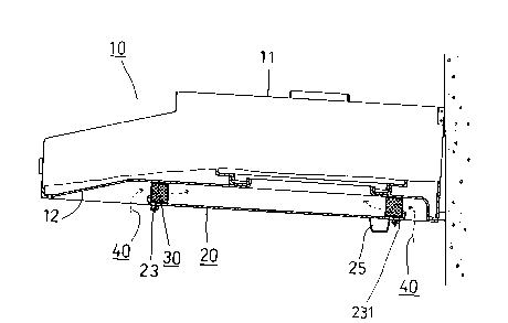
FIG. 2 shows a sectional view of a portion taken along the
line 2-2 as shown in FIG. 1;
FIG. 3 shows a secitonal view of a portion taken along the
line 3-3 as shown in FIG. 1;
FIG. 4 shows a plan view illustrating the position
relationship between the filtration member and the base board
of the present invention;
FIG. 5 shows the filtration member of a second preferred
embodiment of the present invention;
FIG. 6 shows the filtration member of a third preferred
embodiment of the present invention;and
FIG. 7 shows an enlarged sectional view of the filtration
member as shown in FIG. 6.
DETAILED DESCRIPTION OF THE EMBODIMENTS
As shown in FIGS. 1-4, a smoke exhauster of the first
preferred embodiment of the present invention comprises the
component parts which are described explicitly hereinafter.
A housing 10 is made up of an upper casing 11 and a bottom

21~9275
board 12. The upper casing 11 is provided therein with a fume
drawing device 13 which is composed of a bellows 131 and an
impeller 132. The bottom board 12 is provided with a fume
admitting port 121.
A base board 20 of a rectangular shape is provided with a
main board portion 21 which is smaller in size than the flat
board portion 122 of the bottom board 12 and is provided
peripherally with a stopping portion 22 of an appropriate
height. The four corners of the base board 20 are provided
respectively with a hole 24 extending from the left and the
right outer edges of the main board portion 21 toward the
front and the rear center lines in an opposite and slightly
slanted manner. The base board 20 can be detachably fastened
under the bottom board 12 by means of four fastening members
23. An oil depositing member 25 is disposed at the rear side
of the main board portion 21.
A filtration member 30 of a rectangular frame body has a
periphery urging the inner side wall of the stopping portion 22
of the base board 20. The top and the bottom of the filtration
member 30 are attached respectively with the bottom of the
bottom board 12 and the top of the main board portion 21.
As the smoke exhauster is started, the impeller 132 is
actuated to draw the cooking fume to move in the direction
indicated by an arrow 40 to pass through the filtration member
30. The filtered fume is then allowed to flow into the fume

21~92~5
drawing device 13 via the fume admitting port 121 before being
exhausted via the fume discharging port 14 located at the top
of the upper casing 11. The used and dirty filtration member
30 can be removed for replacement by loosening a leakproof ring
231 and a nut 232 of the fastening member 23 so as to
facilitate the removal of the base board 20. The dirty
filtration member 30 may be washed or replaced.
As shown in FIG. 5, the filtration member 30A of the
second preferred embodiment of the present invention is
different from the filtration member 30 of the first preferred
embodiment in that the former is composed of four long
striplike filtration elements 31, 32, 33 and 34.
As shown in FIGS. 6 and 7, the filtration member 50 of the
third preferred embodiment of the present invention is composed
of four long striplike filtration elements 60 which form a
rectangular frame. Each of the four filtration elements 60 is
made of a fireproof and heat-resistant material and is provided
with a bottom plate portion 61 which is in turn provided
therein with an inner wall plate portion 62 extending upwards
and an outer wall plate portion 63 extending upwards. The
filtration elements 60 are further provided respectively and
pivotally at the top thereof with an upper cover 64. In
addition, each filtration element 60 is provided respectively
at both ends of the longitudinal axis thereof with an end plate
( not shown in the drawing ) for forming therein a receiving

21~92~5
space in which a filtration material 68, such as active carbon,
is disposed. The bottom plate portion 61 is provided on the
outer edge thereof with a short plate portion 65 extending
outwards and having on the outer edge thereof an upright plate
portion 66 extending upwards. The upright plate portion 66 is
provided on the top thereof with a locating portion 67.
Futhermore, the bottom plate portion 61 and the short plate
portion 65 are provided respectively with a plurality of oil
dripping holes 6-11, 651. The inner wall plate portion 62 and
0 the outer wall plate portion 63 are provided respectively with
a plurality of through holes 621, 631. In combination, the
locating portion 67 is joined with the stopping portion 22
surrounding the base board 20. The bottom plate portion 61 and
the top of the main board portion 21 of the base board remain
apart by a predetermined distance. The upper cover 64 is
attached to the bottom of the bottom board 12. In operation,
the cooking fume is allowed to flow through the filtration
material 68 via the through holes 631 of the outer wall plate
portion 63 and is then let out via the through holes 621 of the
inner wall plate portion 62. The fume is then guided to the
bellows 131 via the fume admitting port 121 of the bottom board
12. As the filtration material 68 gets dirty, it can be
replaced by opening the upper cover 64.
The filtration element 60 of the third preferred
embodiment of the present invention may be provided therein

21~9275
with a deodorant in addition to the filtration material 6a.
While the invention has been described in connection with
what is presently considered to be the most practical and
preferred embodiments, it is to be understood that the
invention is not to be limited to the disclosed embodiments but
on the contrary, is intended to cover various moditications and
equivalent arrangements included within the spirit and scope of
interpretation so as to encompass all such modifications and
equivalent structures.

Representative Drawing
A single figure which represents the drawing illustrating the invention.
Administrative Status

2024-08-01:As part of the Next Generation Patents (NGP) transition, the Canadian Patents Database (CPD) now contains a more detailed Event History, which replicates the Event Log of our new back-office solution.

Please note that "Inactive:" events refers to events no longer in use in our new back-office solution.

For a clearer understanding of the status of the application/patent presented on this page, the site Disclaimer , as well as the definitions for Patent , Event History , Maintenance Fee  and Payment History  should be consulted.

Event History

Description Date
Inactive: Agents merged 2013-10-18
Time Limit for Reversal Expired 2004-12-29
Letter Sent 2003-12-29
Grant by Issuance 1997-07-22
Notice of Allowance is Issued 1997-02-18
Application Published (Open to Public Inspection) 1996-06-30
All Requirements for Examination Determined Compliant 1994-12-29
Request for Examination Requirements Determined Compliant 1994-12-29

Abandonment History

There is no abandonment history.

Fee History

Fee Type Anniversary Year Due Date Paid Date
MF (patent, 3rd anniv.) - small 1997-12-29 1997-11-18
MF (patent, 4th anniv.) - small 1998-12-29 1998-12-11
MF (patent, 5th anniv.) - small 1999-12-29 1999-12-14
MF (patent, 6th anniv.) - small 2000-12-29 2000-12-19
MF (patent, 7th anniv.) - small 2001-12-31 2001-12-13
MF (patent, 8th anniv.) - small 2002-12-30 2002-12-12
Owners on Record

Note: Records showing the ownership history in alphabetical order.

Current Owners on Record
SUN-SING JANG
Past Owners on Record
None
Past Owners that do not appear in the "Owners on Record" listing will appear in other documentation within the application.
Documents

To view selected files, please enter reCAPTCHA code :


To view images, click a link in the Document Description column. To download the documents, select one or more checkboxes in the first column and then click the "Download Selected in PDF format (Zip Archive)" or the "Download Selected as Single PDF" button.

List of published and non-published patent-specific documents on the CPD .

If you have any difficulty accessing content, you can call the Client Service Centre at 1-866-997-1936 or send them an e-mail at CIPO Client Service Centre.


Document
Description 
Date
(yyyy-mm-dd) 
Number of pages   Size of Image (KB) 
Cover Page 1996-08-21 1 13
Abstract 1996-08-21 1 17
Drawings 1996-08-21 5 76
Claims 1996-08-21 3 102
Description 1996-08-21 6 176
Description 1996-06-30 6 176
Abstract 1996-06-30 1 17
Cover Page 1996-08-20 1 13
Claims 1996-06-30 3 102
Drawings 1996-06-30 5 76
Abstract 1997-05-26 1 18
Cover Page 1997-05-26 1 11
Description 1997-05-26 6 179
Claims 1997-05-26 3 104
Drawings 1997-05-26 5 75
Representative drawing 1999-06-22 1 7
Maintenance Fee Notice 2004-02-23 1 175
Fees 2002-12-12 1 45
Fees 2001-12-13 1 57
Fees 1998-12-11 1 57
Fees 1997-11-18 1 59
Fees 1999-12-14 1 56
Fees 2000-12-19 1 55
Prosecution correspondence 1994-12-29 2 96
Correspondence related to formalities 1997-03-27 1 52