Language selection

Search

Patent 2139370 Summary

Third-party information liability

Some of the information on this Web page has been provided by external sources. The Government of Canada is not responsible for the accuracy, reliability or currency of the information supplied by external sources. Users wishing to rely upon this information should consult directly with the source of the information. Content provided by external sources is not subject to official languages, privacy and accessibility requirements.

Claims and Abstract availability

Any discrepancies in the text and image of the Claims and Abstract are due to differing posting times. Text of the Claims and Abstract are posted:

  • At the time the application is open to public inspection;
  • At the time of issue of the patent (grant).
(12) Patent: (11) CA 2139370
(54) English Title: ELECTRICAL RECEPTACLE AND TERMINALS
(54) French Title: PRISE DE COURANT ET BORNES
Status: Expired and beyond the Period of Reversal
Bibliographic Data
(51) International Patent Classification (IPC):
  • H01R 13/11 (2006.01)
  • H01R 04/48 (2006.01)
  • H01R 13/115 (2006.01)
  • H01R 25/00 (2006.01)
  • H01R 43/16 (2006.01)
(72) Inventors :
  • MEHTA, PARAG J. (United States of America)
(73) Owners :
  • PASS & SEYMOUR, INC.
(71) Applicants :
  • PASS & SEYMOUR, INC. (United States of America)
(74) Agent: MACRAE & CO.
(74) Associate agent:
(45) Issued: 1998-04-07
(22) Filed Date: 1994-12-30
(41) Open to Public Inspection: 1995-07-15
Examination requested: 1994-12-30
Availability of licence: N/A
Dedicated to the Public: N/A
(25) Language of filing: English

Patent Cooperation Treaty (PCT): No

(30) Application Priority Data:
Application No. Country/Territory Date
181,042 (United States of America) 1994-01-14

Abstracts

English Abstract


A duplex receptacle consisting of molded plastic base and
cover portions, a pair of terminals having female contacts for
receiving plug blades, and a mounting strap. The terminals are
formed with a minimum of bending operations from blanks cut in
succession from a metal strip in a manner minimizing the distance
of die progression per blank, and reducing scrap. The contacts
have a configuration which enhances electrical communication with
the inserted plug blades. Portions of the cover cooperate with the
contacts to increase blade retention force. A portion of the
mounting strap is exposed through an opening in the cover to
provide further advantages. The spring arms on the terminals
include structure which inhibits dislodgement of conductors
connected to the receptacle by push-wire terminations.


French Abstract

Prise de courant double comprenant : une base et un recouvrement de plastique moulé; une paire de bornes ayant des contacts femelles qui reçoivent des tiges de fiche; une bride de fixation. Les bornes sont formées grâce à un minimum d'opérations de flexion des ébauches coupées en succession dans une bande métallique, de façon à diminuer la distance de progression de la matrice pour chaque ébauche, et à réduire les rognures. La configuration des contacts permet d'améliorer la communication électrique avec les tiges de fiche insérées. Des parties du recouvrement collaborent avec les contacts, afin d'augmenter la force de rétention des tiges. Une partie de la bride de fixation est exposée par une ouverture pratiquée dans le recouvrement, afin de présenter encore plus d'avantages. Les bras à ressort sur les bornes comportent une structure qui empêche le détachement des conducteurs reliés à la prise de courant par des raccords de fil- poussoir.

Claims

Note: Claims are shown in the official language in which they were submitted.


What Is Claimed Is:
1. An electrical terminal having female contacts for sliding
insertion and withdrawal along a predetermined, linear path of a
plug blade having opposite, flat surfaces, said terminal
comprising:
a) a first wall portion having first, inner and outer
surfaces;
b) means for connecting an electrical conductor in
conducting contact with a predetermined, planar part of said first
wall portion;
c) a second wall portion having second, inner and outer
surfaces;
d) a first, resilient arm integrally connecting said
first and second wall portions;
e) a third wall portion having third, inner and outer
surfaces;
f) a second, resilient arm integrally connecting said
first and third wall portions;
g) said second and third wall portions being inwardly
offset by said first and second arms from said first wall portion
in a direction transverse to the plane of said planar part;
h) said second and third wall portions being positioned
with said second inner surface contacting said third outer surface
along a free edge of said second wall portion remote from said
first arm; and
i) blade entry means defined by flared end portions
18

extending outwardly from said second outer and said third inner
surfaces for insertion therebetween of said plug blade along said
linear path as at least one of said first and second arms is flexed
to permit separation of said free edge from said third outer
surface with said opposite surfaces of said blade respectively
contacting said free edge and said third outer surface.
2. The invention according to claim 1 wherein said free edge
is substantially linear and disposed at an acute angle with respect
to said linear direction.
3. The invention according to claim 2 wherein said angle is
about 45°.
4. The invention according to claim 1 wherein said first wall
portion is bent inwardly at a first angle with respect to said
planar part, and both said first and second arms are curved
outwardly.
5. The invention according to claim 4 wherein said first
angle is substantially 90°.
6. The invention according to claim 5 wherein said second arm
is curved about 90°, and said third wall surfaces are planar and
substantially parallel to the plane of said planar part of said
first wall portion.
7. The invention according to claim 1 wherein said third
inner and outer surfaces are in parallel planes substantially
parallel to said planar part of said first wall portion, and said
second inner surface is disposed in a plane at an acute angle to
said third outer surface when said free edge is in contact with
19

said third outer surface.
8. The invention according to claim 7 wherein said acute
angle is between about 5° and 10°.
9. The invention according to claim 8 wherein said first arm,
over at least most of its length, is closer than said second arm to
said first wall.
10. The invention according to claim 9 wherein said first and
second arms are in spaced, substantially side-by-side relation.
11. An electrical receptacle for placing a pair of plug
blades having planar surfaces of predetermined width in electrical
communication with a source of AC power, said receptacle
comprising:
a) a base portion of dielectric material;
b) a cover portion of dielectric material having a pair
of openings through which said blades may be inserted and withdrawn
by movement along a predetermined, linear path, said base and cover
portions cooperatively defining an internal cavity;
c) a pair of terminals, each including
i) means for connection thereto of an
electrical conductor;
ii) a first contact strip having first,
planar, inner and outer surfaces bounded on
one side by a contact edge;
iii) a second contact strip having
second, planar, inner and outer surfaces;
iv) first and second support means for

said first and second contact strips,
respectively, at least one of said support
means being resilient to permit limited,
relative movement of said contact strips from
an unflexed position, to which said contact
strips are biased by said support means, to a
flexed position;
v) said contact strips, when in said
unflexed position, being supported with said
first strip contact edge in essentially linear
contact with said second strip outer surface,
and said first inner and second outer surfaces
disposed in planes extending at an acute angle
from said contact edge; and
vi) a pair of outwardly flared end
portions respectively extending from said
first and second contact strips; and
d) positioning means for holding said contact strips
within said cavity with said end portions of said terminals aligned
with a respective one of said pair of openings, whereby insertion
of said blades through said openings moves said blades between said
contact strips and moves the latter to said flexed position with
said first strip contact edge in contact with one and said second
strip outer surface in contact with the other of said blade
surfaces.
12. The invention according to claim 11 wherein said contact
21

edge is substantially linear.
13. The invention according to claim 12 wherein said edge is
disposed at a predetermined angle between about 30° to 60° with
respect to said linear path.
14. The invention according to claim 13 wherein said contact
edge is in contact over at least about 90% of its entire length
with said one of said blade surfaces when said blades are fully
inserted.
15. The invention according to claim 13 wherein at least a
portion of said contact edge is in contact with said one surface of
said blade over the full range of travel of said blade between said
first and second contact strips.
16. The invention according to claim 11 wherein said acute
angle is between about 5° and 10°.
17. The invention according to claim 11 and further including
means positioned within said cavity in the path of movement of one
of said contact strips of each of said terminals toward said flexed
position thereof.
18. The invention according to claim 17 wherein said means
within said cavity extend integrally from said cover portion
inwardly of said cavity.
19. The invention according to claim 18 wherein said means
within said cavity comprise a pair of post members respectively
positioned in the path of movement of one of said contact strips of
each of said pair of terminals.
20. The invention according to claim 19 wherein each of said
22

post members extends from said cover portion to a terminal end, and
said one contact strip contacts the respective one of said post
members adjacent said terminal end when said blade is fully
inserted between said contact strips, whereby said post members
oppose further movement of said one contact strip toward said
flexed position and enhance the retaining force exerted by said
contact strips on said blades.
21. The invention according to claim 20 wherein said one
contact strip is said first contact strip.
22. The invention according to claim 21 wherein said first
support means comprises a resilient arm upon which said first
contact strip is supported for movement between said unflexed and
flexed positions.
23. An electrical receptacle for connection in an AC circuit
to receive a pair of male plug blades, said receptacle comprising:
a) a base portion of dielectric material;
b) a cover portion of dielectric material affixed to
said base portion to define therewith an internal cavity and having
a pair of openings configured and positioned for insertion and
withdrawal therethrough of said plug blades;
c) a pair of terminals each having first and second
contact strips with opposed portions forming a pair of female
contacts for receiving said plug blades;
d) resilient support means for at least one of said
contact strips of each of said terminals, said support means
exerting a biasing force tending to move said one contact strip in
23

a direction toward contact of said opposed portions and to
resiliently resist movement of said one contact strip in the
opposite direction by insertion of said plug blades between said
opposed portions; and
e) obstruction means having a limited degree of
resilience positioned within said cavity in the path of movement in
said opposite direction of said one contact strip, insertion of
said blades between said opposed portions serving to move said one
contact strip of each of said terminals into contact with a
respective one of said obstruction means, whereby the latter
augments said biasing force and increases the retaining force
exerted on said blades by said opposed portions of said contact
strips.
24. The invention according to claim 23 wherein said
obstruction means comprise a pair of post members.
25. The invention according to claim 24 wherein said post
members extend into said cavity integrally from one of said base
portion and cover portion.
26. The invention according to claim 25 wherein said post
members extend integrally from said cover to terminal ends
respectively positioned adjacent said one contact strip of said
pair of terminals.
27. The invention according to claim 26 wherein said pair of
openings are elongated, parallel and laterally spaced from one
another, said cover portion has an inner surface directed toward
said cavity, and said post members extend integrally from said
24

inner surface adjacent respective ones of said openings.
28. The invention according to claim 27 wherein said post
members are laterally, outwardly adjacent an elongated side of
respective ones of said openings.
29. a duplex wall receptacle for connection to an AC power
source, said receptacle comprising:
a) a base portion of dielectric material having a rear
wall, opposite side walls and opposite end walls, said side and end
walls terminating in base edge portions;
b) a cover portion of dielectric material having a front
wall with front and back sides and wall means on said back side
defining cover edge portions configured for mating engagement with
said base edge portions, whereby said base and cover portions
cooperatively define an enclosed cavity;
c) said front side of said cover portion including first
and second end portions and a central portion, each of said end
portions having a plurality of first openings therethrough for
passage of the blades of an electrical plug, said end portions
having forward surfaces lying in a common, first plane and said
central portion having a forward surface lying in a second plane,
parallel to said first plane and spaced therefrom in the direction
of said base portion;
d) means defining a second opening of predetermined
peripheral outline extending through said central portion and
between said end portions; and
e) a mounting strap having an intermediate portion

positioned within and extending through said cavity and ear
portions extending outwardly from said opposite end walls, said
strap being captured between and held in a fixed position by
opposing parts of said base and cover portions with a planar
surface of said intermediate portion exposed through said second
opening and lying substantially in said second plane.
30. The invention according to claim 29 and further including
a threaded opening in said intermediate portion exposed through
said second opening for receiving a wall plate mounting screw.
31. The invention according to claim 30 wherein said threaded
opening is located substantially centrally of said second opening.
32. The invention according to claim 31 wherein said
predetermined outline is substantially rectangular.
33. The invention according to claim 32 wherein said second
opening extends longitudinally between said end portions and
laterally a distance slightly greater than the width of said
intermediate portion of said strap exposed through said second
opening.
34. The invention according to claim 29 wherein said
intermediate and ear portions of said strap have contiguous,
substantially flat and coplanar, opposite surfaces.
35. The invention according to claim 34 wherein said
intermediate portion has substantially linear, parallel, side
edges.
36. The invention according to claim 35 wherein said
intermediate portion of said strap exposed through said second
26

opening has a predetermined, uniform width and said second opening
has parallel side edges spaced a few thousandths of an inch greater
than said predetermined width.
37. The invention according to claim 36 wherein said strap is
of electrically conducting material and includes a pair of third
openings aligned with respective ones of each of said plurality of
first openings for receiving, in electrical contact, the grounding
prongs of plugs connected to said receptacle.
38. The invention according to claim 35 and further including
first and second retaining walls within said cavity having
opposing, parallel walls spaced a few thousandths of an inch
greater than the width of a predetermined length of said
intermediate portion of said strap lying between said retaining
walls.
39. The invention according to claim 38 wherein said
retaining walls are formed integrally with said base portion and
lie between and parallel to said opposite side walls.
40. The invention according to claim 30 and further including
support means positioned between said first and second retaining
walls, one of said opposite surfaces of said predetermined length
of said intermediate portion of said strap lying upon said support
means.
41. A wiring device for connection to hot and neutral
conductors of an AC electrical circuit, said device comprising:
a) housing means defining an enclosed cavity;
b) a terminal of electrically conducting material having
27

a fixed wall and a spring arm positioned within said cavity, said
spring arm extending from a resiliently supported end to a free end
having a central portion of predetermined width in close proximity
to said fixed wall and movable with respect thereto by application
of force to said spring arm;
c) a passageway through said housing means having a
central axis substantially aligned with central portion of said
free end, whereby forcible insertion of an end of an elongated
electrical conductor along said axis applies said force to said
spring arm, moving said free end away from said fixed wall and
engaging said conductor end between said central portion of said
free arm and said fixed wall in electrical communication with said
terminal; and
d) a protrusion extending outwardly from said free end
at one side of said central portion, laterally spaced from said
central axis and extending toward said fixed wall, whereby said
protrusions resist disengagement of said conductor end by lateral
movement thereof in the direction of said protrusion.
42. The invention according to claim 41 wherein said central
portion comprises an essentially linear edge of said free end.
43. The invention according to claim 42 wherein said
protrusion terminates in a linear edge substantially parallel to
said central portion linear edge.
44. The invention according to claim 41 wherein said wiring
device includes a pair of said terminals, each having a fixed wall
and spring arm, and said housing means includes a pair of said
28

passageways having axes respectively aligned with said free ends of
said spring arms for connection of a hot conductor to one and a
neutral conductor to the other of said pair of terminals.
45. The invention according to claim 44 wherein said
terminals each include female contacts for receiving blades of an
electrical plug.
46. A succession of identical blank layouts on a flat,
elongated metal strip having linear, parallel, side edges for cut-out
of successive blanks prior to the forming thereof into
electrical terminals of predetermined configuration, said
succession of blank layouts comprising:
a) a first blank layout having first side edges
coextensive with said side edges of said strip, and first,
continuous, non-linear, top and bottom edges extending between said
first side edges;
b) a second blank layout having second side edges
coextensive with said side edges of said strip, and second,
continuous, non-linear, top and bottom edges extending between said
second side edges;
c) said first bottom edge and said second top edge
having coextensive first and second portions thereof extending
inwardly from opposite ones of said first and second side edges,
and respective, non-coextensive, third portions defining a unitary
scrap portion;
d) each of said blank layouts having an overall length
L between the points on its top and bottom edges which are farthest
29

spaced in a longitudinal direction parallel to said side edges;
e) at least part of each of said first and second
portions of said first bottom edge being closer than at least part
of said third portion of said second top edge to said second bottom
edge, whereby the overall length L1 between the points on said
first top edge and said second bottom edge which are farthest
spaced in said longitudinal direction is less than 2L.
47. The succession of blank layouts of claim 46 wherein L1
equals approximately 1.85L.
48. The succession of blank layouts of claim 46 wherein the
total scrap associated with each of said blank layouts consists of
said unitary scrap portion and a pair of identical, discrete scrap
portion.
49. The succession of blank layouts of claim 46 wherein the
total surface area of scrap associated with each of said blank
layouts is approximately 20% of the surface area of one of said
blank layouts.
50. The succession of blank layouts of claim 46 wherein each
of said blank layouts consist of right and left halves which are
mirror images of one another on opposite sides of a centerline
parallel to said side edges.

Description

Note: Descriptions are shown in the official language in which they were submitted.


2139370
Improved Electrical Receptacle an~ Terminals
~ac~qround Of The Invention
The present invention relates to wiring devices, and more
particularly to novel and improved electrical receptacles having
terminals for receiving the blades of conventional plugs.
The prior art is replete with variations in the design of the
common receptacle which is connected to a source of AC power in the
wiring system of a house or other building structure. Although
such receptacles may be mounted in virtually any desired location
or environment, they are most familiar as household devices
commonly termed wall outlets or receptacles. An appliance, or
other item requiring AC power is connected to the power source by
male blades, usually extending from a plug at the end of a cord,
which are inserted in female contacts within the receptacle.
Building codes in many localities require the use of wall
outlets, as well as other wiring devices, which conform to certain
standards prescribed by agencies or associations such as UL and
NEMA. Therefore, it is not surprising that the wall outlets of
different manufacturers have many features in common. Countless
variations are possible, however, while remaining within the
prescribed guidelines, and efforts to improve and simplify such
devices continue.
In the most general terms, it is the object of the present
invention to provide a wiring device in the nature of a wall outlet
which conforms to all presently required standards while having

2139370
improved structural features contributing to both enhanced
operating characteristics and economy of manufacture.
Additional, more specific objects are to provide a wall
outlet:
having terminals including female contacts which are
configured to ~h~nce good electrical communication with male
blades inserted into such contacts throughout travel of the blades
into and out of the contacts,
including terminals with spring contacts for push-wire
terminations with improved wire-retention characteristics,
having a base, cover, mounting strap and terminals with
structural features and positional relationships of the elements,
particularly the cover and strap, permitting conformity to required
parameters while simplifying and economizing manufacture,
wherein the cover includes integral portions cooperatively
positioned with respect to portions of the female contacts to
enhance the blade-retaining capabilities thereof,
-having terminals formed from sheet metal blanks in a manner
minimizing the distance of progression between successive blanks,
and reducing scrap, and
having terminals, including blade-receiving contacts, of
improved design permitting elimination of bending steps, as
compared to prior art terminals of this type, in forming the
terminals from precut blanks.
Other objects will in part be obvious and will in part appear
hereinafter.

2139370
,
Summary of The Invention
The aforementioned objects are achieved in a disclosed,
preferred embodiment of a duplex wall outlet configured for
mounting in a st~n~rd junction box and covered by a conventional
wall plate. The duplex receptacle is designed to comply with all
current NEMA and UL specifications, thus having many features in
common with other commercial receptacles. For example, receptacles
of the prior art and of the present invention include a base and a
cover of molded plastic which fit together to define internal
cavities which hold portions of a pair of terminals and a mounting
strap. Hot and neutral lines of the wiring system wherein the
receptacle is included are respectively connected to the two
terminals and a ground line is connected to the mounting strap.
The cover includes two sets of openings for receiving the blades of
st~n~rd plugs connected to the receptacle.
The mounting strap is of the type extending straight through
the cover and base, between the outwardly extending parts at each
end through which the mounting screws extend. The only bends in
the strap are to form the tab at the side, adjacent one end, having
a tapped opening for the screw which retains the ground line when
such is utilized. The cover has an opening to expose a central
portion of the strap which includes a tapped opening for the wall
plate mounting screw. As will be explained later, this unique
arrangement permits the use of this advantageous form of strap
while complying with both NEMA and UL dimensional standards.
The terminals are formed by appropriately bending blanks cut

2139370
from a strip of electrically conductive sheet metal. The blanks
are designed with parts overlapping adjacent blanks to minimize the
distance of progression between successive blanks, and to reduce
scrap. Also, the terminals are designed to minimize the number of
bends necessary to provide the final configuration, and to ensure
good contact with the plug blades throughout movement thereof when
being inserted into and withdrawn from the female contacts of the
terminals.
The terminals are provided with both screw and push-wire
termination means for the connection of electrical lines to the
receptacle. The push-wire terminations include the usual spring
arms which urge the end of a bare wire inserted through an opening
in the bac~ of the base into firm engagement with a stationary part
of the terminal. In the terminals of the present invention, the
spring arms are formed with an outward projection at each side to
inhibit dislodgement of the wire retained thereby.
An additional feature of the receptacle is the provision of a
plurality of semi-rigid posts extending integrally from the inner
side of the cover into the cavities where the female, blade-
receiving, terminal contacts are positioned. The posts arecooperatively positioned with respect to the portions of the
contacts which are moved outwardly as the blades are inserted so
that such portions contact the posts and are inhibited from free,
outward movement. This arrangement enhances the blade-retaining
capability of the receptacle.
The features of the receptacle summarized above will be more

2139370
fully understood and appreciated from the following detailed
description of the preferred embodiment,~taken in conjunction with
the accompanying drawings, wherein:
Brief Description Of The Drawinqs
5Figure 1 is a perspective view of the receptacle in fully
assembled condition;
Figure 2 is a side elevational view of the assembled
receptacle, with portions broken away;
Figure 3 is an exploded perspective view of the components of
10the receptacle, together with a junction box and wall plate
employed with the receptacle;
Figures 4 and 5 are front and rear elevational views,
respectively, of the receptacle base;
Figures 4A and 4B are elevational views in section on the
15lines 4A-4A and 4B-4B, respectively, of Figure 4;
Figures 6 and 7 are front and rear elevational views,
respectively, of the receptacle cover;
Figures 8 and 9 are side elevational views, taken from
opposite sides, of one of the two, identical, receptacle terminals;
20Figure 10 is a top plan view of the terminal of Figures 8 and
9;
Figure 11 is an enlarged, fragmentary, elevational view, in
section on the line 11-11 of Figure 7;
Figure 12 is a fragmentary, elevational view, in section on
25the line 12-12 of Figure 6 which includes, in addition to portions
of the cover, portions of the base and one of the terminals with a

2139370
-
plug blade positioned between the contacts;
- Figure 13 is a fragmentary, elevational view taken on the line
13-13 of Figure 5, showing portions of the receptacle contacts with
the end of a conductor inserted therein to effect a push-wire
termination;
Figure 14 is an enlarged, fragmentary, elevational view as
seen from the line 14-14 of Figure 8, showing the inserted
electrical wire of Figure 13 engaged between two portions of the
ter~i~l; and
Figure 15 is a plan view of a strip of sheet metal showing a
succession of blanks from which the receptacle terminals are formed
laid out thereon.
Detailed Description
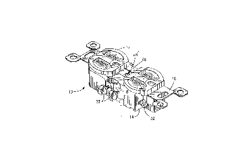
Referring now to the drawings, in Figures 1 and 2 is shown an
assembled duplex receptacle, denoted generally by reference numeral
10, embodying the features of the present invention. Receptacle 10
includes cover 12 and base 14, each formed as a unitary, molded
part of a dielectric material such as a suitable plastic, and strap
16. Receptacle 10 further includes a pair of terminals 18 and 20,
exteriorly exposed portions of which are seen in Figures 1 and 2,
both terminals being shown in their entireties in the exploded
perspective view of Figure 3. Respective pairs of screws 22 and 24
engage threaded openings in terminals 18 and 20 for securing the
stripped ends of electrical wires thereto.
As will be apparent from the exploded perspective view (Fig.
3), receptacle 10 consists essentially of the aforementioned five

2139~0
elements, i.e., cover 12, base 14, strap 16 and two terminals 18
and 20. Details of construction of the-~over, base and terminals
are shown and described in connection with later drawing Figures.
Mounting and grounding strap 16 is shown in its entirety only in
Figure 3, and portions thereof are visible in Figures 1 and 2.
Strap 16 is formed from a blank of galvanized steel or other
appropriate sheet metal having a thickness of substantialIy .040"
to comply with certain dimensional requirements of both NEMA and UL
codes, as explained later in more detail.
Strap 16 is essentially flat, having opposite, planar
surfaces, with no bends other than the ones necessary to form
depending tab 26 and small tabs 28 extending outwardly therefrom.
Threaded opening 30 (Fig. 3~ in tab 26 receives screw 32 (Fig. 1)
for the purpose of securing a ground wire (not shown) to the strap
in appropriate installations. Ear portions 34, 34', having
respective openings 36, 36', extend from opposite ends of
intermediate portion 38 of strap 16. In the assembled condition of
receptacle 10, intermediate portion 3B extends through a cavity
between cover 12 and base 14, as described later in more detail,
with ear portions 34, 34' extending outwardly from opposite ends of
the receptacle.
As indicated in Figure 3, receptacle 10 is mounted in the
usual manner in a st~n~rd utility box 40 by means of screws 42,
42' passing through openings 36, 36' and received in threaded
2S openings 44, 44' in box 40. Strap 16 further includes a centrally
located, threaded opening 46 for receiving screw 48 which passes

2139370
-
through oren; n~ 50 in conventional wall plate 52 which is provided
in the usual manner to cover portions of~the installed receptacle.
Grounding contacts 54, 54' are riveted to strap 16 and include
resilient contacts extending through respective openings in strap
16 to receive the ground prongs of electrical plugs connected to
receptacle 10.~
Referring now to Figures 4 and 5, as well as to Figure 3, the
configuration of base 14 will be described in greater detail. Base
14 includes rear wall 54, opposite side walls 56, 56' and opposite
end walls 58, 58'. Side walls 56, 56' are seen to be
discontinuous, providing open spaces at the center through which
the screw-receiving portions of terminals 18 and 20 are exposed.
The outwardly-facing surfaces of walls 54, 56, 56' and 58, 58'
define the exterior of base 14, and the inwardly-facing surfaces
define a cavity, open at the top (front) and closed by cover 12 in
the assembled condition of receptacle 10, the cover and base
meeting in permanently bonded relation along the line indicated by
reference numeral 60 in Figure 2.
A plurality of internal wall means are provided within the
cavity formed by the peripheral walls of base 14. A pair of
spaced, parallel walls 62, 62~ (Fig. 3) extend longit~ n~lly of
the cavity, from rear wall 54 to terminal edges. Wall 62 has
terminal edge portions 64 extending from opposite ends of the wall
toward the center and separated by intermediate edge portion 66;
likewise, wall 62' has edge portions 64' separated by intermediate
edge portion 66'. It will be noted that edge portions 64 and 64'

2139370
-- , .
lie in a plane higher (i.e., farther from rear wall 54) than
intermediate portions 66 and 66'. - A plurality of wall means 68
extend-laterally between walls 62, 62', and all terminate in the
plane of edges 66 and 66'.
S Wall means 70, 70' extend laterally from walls 62, 62',
respectively, to the spaces between opposite side walls 56, 56'.
A pair of identical wall means, both denoted by reference numeral
72, extend laterally from wall 62, on opposite sides of and equally
spaced from wall means 70; a second pair of wall means 72' extend
laterally from wall 62' on opposite sides of wall means 70'. Four
pedestals 74 are provided at essentially the corners of the cavity,
extending from the inner surface of rear wall 54. Four round
openings 76 extend through rear wall 54, and four open slots 78 are
positioned respectively adjacent openings 76, for purposes
explained later.
Details of cover 12 are shown in Figures 6 and 7, as well as
in certain sectional views. As in the usual duplex receptacle, the
outwardly facing side of cover 12 includes a pair of identical,
plug-receiving portions 80, 80' ! each having first (82, 82') and
second (84, 84') elongated, through openings for receiving flat
blades or prongs of an electrical plug, and D-shaped, through
openings 86, 86' for receiving plug grounding prongs. In the
receptacle of the present invention, portions 80 and 80' are
connected to one another by bridging portions 88 and 88' with
2S rectangular opening 9o bounded on its ends by plug-receiving
portions 80, 80' and on its sides by bridging portions 88, 88'.

2139370
.
Ribs 92 extend from the inner surface of cover 12 adjacent
each of elongated openings 82, 82', 84, and 84', each rib having a
surface flush with one side of its respective opening. Posts 94
extend from the inner surface of cover 12 on the opposite sides of
s openings 82, 82', 84 and 84' from ribs 92, the posts being spaced
somewhat from the sides of the openings nearest thereto.
Relatively short ribs 96 extend along portions of openings 82, 82',
84 and 84' on the same sides as posts 94, and a surface of each of
ribs 96 is flush with the side of the opening opposite ribs 92.
Wall means 98 extend longitudinally of the inner surface of cover
12, midway between openings 82, 84 and 82', 84'. Wall means 100
extend from the inner surface of the cover, bounding opposite sides
of opening go.
One of the two identical terminals 18 and 20 is shown in
detail in Figures 8-10, with portions shown in other, fragmentary,
sectional views. As discussed later in more detail, the terminals
are formed from successive blanks cut from a flat sheet of metal
and bent to the final configuration. Each terminal includes two
identical halves, connected by bridging portion 102. On each side
of the bridging portion are first wall portions 104, 104', having
tapped openings 106, 106~ for receiving wire termination screws 22
and 24. Tabs 108, 108' extend from the lower edges of first wall
portions 104, 104' for the purpose of mating with notches in base
14 when the terminals are assembled therewith.
First wall portions 104, 104' are bent at substantially 90~,
as indicated at 110, 110' and connected by first, resilient arms

2139370
-
112, 112' to second wall portions 114, 114'. First wall portions
104, 104' are further connected by second, resilient arms 116, 116'
to third wall portions 118, 118~. End portions 120, 120' of second
wall portions 114, 114' and end portions 122, 122' of third wall
portions 118, 118' are flared outwardly with respect to one
another. Aside from flared end portions 120, 120', 122 and 122',
the inner and outer surfaces of all of wall portions 104, 104',
114, 114', 118 and 118' are planar, the wall surfaces seen in
Figures 8 and 9 being termed outer and inner surfaces,
respectively. The outer surfaces of first wall portions 104, 104'
are the only externally exposed portions of terminals 18 and 20 in
the assembled condition of receptacle 10.
Flared end portions 120, 120' and 122, 122' provide entry
means for blade 124 of an electrical plug inserted linearly in the
lS direction of arrow 126 through one of the elongated openings 82,
82', 84 and 84' for engagement of opposite blade surfaces between
the contacts provided by second and third wall portions 114 and 118
or 114' and 118'. Edges 128, 128' of second wall portions 114,
114' are at an acute angle, preferably about 45~, to plug insertion
direction 126, as are edges 130, 130~ of third wall portions 118,
118'. As best seen in Figure 10, arms 112 and 116 are bent or
curved, the bend in arm 112 being closer to wall 104 than the bend
in arm 116. The bend in arm 116 is substantially 90~, whereby the
inner and outer surfaces of wall 118 are essentially parallel to
those of wall 104. The bend in arm 112 is less than 90~, whereby
the surfaces of wall 114 are at an acute angle, preferably between
.... . . . . .

2139370
about 5~ and 10~, to the surfaces of wall 118. The relative
positions and the degree of curvature of the bends in arms 112 and
116 results in some amount of overlapping of walls 114 and 118 with
the inner surface of wall 114 contacting the outer surface of wall
5118 essentially along the line of free edge 128. Thus, opposite
surfaces of blade 124 are contacted by the outer surface of wall
118 and by free edge 128 of wall 114 during essentially the full
range of travel of the blade between the terminal contacts, thereby
providing excellent electrical communication.
10The relative positions of certain portions of the cover, base
and terminals, in the assembled condition of receptacle 10 and with
plug blade 124 inserted, are shown in the fragmentary, sectional
view of Figure 12. Terminals 18 and 20 are placed within the
cavities formed by previously described wall portions of base 14.
15When so positioned, outer portions 71, 71' (Fig. 4B) of walls 70,
70' extend into gaps 101 (Figs. 8, 9) between the two halves of the
terminals, end portions 122, 122' of terminal walls 118, 118'
essentially abut base wall portions 64, 64' and lower portions 134,
134' of the terminals rest upon base pedestals 74. After placing
20strap 16 upon the base, with intermediate portion 38 supported by
base wall portions 68, cover 12 is placed on the base with opposing
edge portions meeting along line 60 (Fig. 2), and the cover and
base are permanently joined by ultrasonic welding.
When cover 12 and base 14 are joined, wall portion 92 on the
25inside of the cover extends to a position directly above end
portion 122 of terminal wall 118, essentially fixing the position

2I39370
of terminal wall 118. Terminal wall 114, of which only a small
fragment is seen in Figure 12 due to t~e position at which the
section is taken, is movable by blade 124 away from wall 118. When
blade 124 is inserted, flared end portion 120 is moved into contact
with post 94. Although end portion 120 and post 94 have some
degree of resilience, both are relatively stiff and the constraint
of movement of terminal wall portion 114 by post 94 provides a
higher degree of holding force on the plug blade than would be
available only from the biasing force of arm 112 on the moveable
contact (wall 114). This feature, coupled with the previously
described line contact of edge 128 with the surface of the plug
blade, ensures both good electrical communication and blade
retention.
The component parts of receptacle 10 are suited for
expeditious assembly, by fully automated means, if desired, simply
by sliding terminals 18 and 20 into the pockets provided by the
wall means within base 14, placing strap 16 on supporting wall
means 68 of the base, and placing cover 12 with its edges in mating
engagement with edge portions of base 14. Referring again to
Figure 2, it will be seen that the distance between the plane of
the upper or front surfaces of cover bridging portions 88, 88' and
line 60, where the cover and base are joined, is indicated as
dimension D. Current NEMA standards require that dimension D have
a maximum of 0.040", while UL standards required that the strap
have a minimum thickness of 0.040". Thus, by making both dimension
D and the thickness of strap 16 equal to 0.040", both standards are
,, . .. , . . ~ . . . .

2139370
,, ,
met in a receptacle having a flat strap, extending straight through
the receptacle with no bends.
Third wall portions 118, 118' are connected at 132, 132' to
spring arms 134, 134' which provide so-called "push wire"
connection of electrical conductors to the terminals. Spring arms
134, 134' are narrower at their connections to third wall portions
118, 118' than at their free ends, which terminate in linear edges
136, 136' with protrusions 138, 138' at each end thereof. The
configuration of spring arms 134, 134' is such that the free ends
are in contact with or close proximity to surfaces of the terminal
formed by portions llo, 110' and arms 116, 116'.
~ n the assembled form of receptacle 10, the axes of the
passageways through base 14 provided by openings 76 intersect
spring arms 134, 134' at or near their free ends. Thus, the end of
an electrical conductor stripped of insulation may be axially
inserted through one of openings 76 and will move the free end of
spring arm 134, 134' away from the adjacent wall of the terminal.
As shown in Figures 13 and 14, conductor 140 is engaged between
terminal edge 136' and the facing surface of arm 116', thus being
in electrical communication with the terminal. Protrusion 138'
inhibits dislodgement of conductor 140 by lateral movement in the
direction of wall 56' of base 14. Conductor 140 may be released
from engagement by insertion of an appropriate tool through the
adjacent slot 78 to temporarily deflect the spring arm away from
the conductor.
As previously mentioned, the terminals are formed from blanks
14

2139370
cut by a conventional die (not shown) successively from a flat
strip of copper or other a~u~riate metal. The layouts of two
successive bla~ks on strip 142 are shown in Figure 15. Portions of
the strip which are used to form the terminals are shown with
conventional surface shading, while portions which become scrap are
cross-hatched. The blank layout permits overlapping of portions of
successive blanks, thereby reducing both the amount of scrap and
the distance of progression through the die between successive
blanks. More specifically, the portions of the blanks which become
10spring arms 134, 134' of one terminal are laterally adjacent
portions which become the wall portions 104, 104', 114, 114', 118
and 118', as well as bridge portions 102 of another terminal. As
is apparent, the side edges of the blank layouts are coextensive
with the side edges of strip 142.
15Each blank layout has non-linear top and bottom edges
extending continuously between the side edges. Top edge 144 of the
first (upper) blank layout of Figure 15 extends between points A
and B. Bottom edge 1~6 of the first blank layout and top edge 148
of the second (lower) blank layout each extend between points A'
and B'. Bottom edge 150 of the second blank layout extends between
points A" and B~. Each blank layout is symmetrical on opposite
sides of the indicated centerline, i.e., the two halves of each
blank layout are mirror images of one another. Each blank layout
has an overall length L (measured in a direction parallel to the
side edges) between the farthest spaced points on the top and
bottom edges. Due to the overlapping of the blank layouts, the

-2139370
-- . ,,
overall length L1 of two successive blank layouts is less than
twice the overall length L of a -sing-~e blank layout; in the
preferred successive blank layouts of the present invention L1 is
approximately 1.85L.
It will be noted that the bottom edge of one blank layout and
the top edge of the next blank layout (e.g., edges 146 and 148)
have first and second, coextensive portions extending inwardly from
the side edges. In Figure 15, edges 146 and 148 are coextensive
between points A' and C, as well as between points B' and C'. Over
third portions of their respective lengths, between points C and
C', edges 146 and 148 are not coextensive and define a unitary
scrap portion 152. The only other scrap portions associated with
each blank layout are relatively small, identical portions 154,
154'. It will be further noted that a single line in each half of
the blank layouts becomes overlapped edges 128 and 130 of the two
contact portions in the finished terminal, being indicated by these
reference numerals in Figure 15.
From the foregoing, it may be seen that receptacle 10 has a
number of features which achieve the objects and advantages
previously enumerated. The strap may be flat, with no bends other
than those forming the tab for attachment of a ground wire, while
still providing a receptacle complying with all current NEMA and UL
standards. The terminals, both in themselves and in con~unction
with other parts of the receptacle, provide enhanced blade contact
and retention, as well as improved spring arms for push-wire
terminations. The terminals are economically formed with a minimum
16

2139370
of h~n~;ng operations from blanks cut successively from a metal
strip with minimized die progression and-scrap.

Representative Drawing
A single figure which represents the drawing illustrating the invention.
Administrative Status

2024-08-01:As part of the Next Generation Patents (NGP) transition, the Canadian Patents Database (CPD) now contains a more detailed Event History, which replicates the Event Log of our new back-office solution.

Please note that "Inactive:" events refers to events no longer in use in our new back-office solution.

For a clearer understanding of the status of the application/patent presented on this page, the site Disclaimer , as well as the definitions for Patent , Event History , Maintenance Fee  and Payment History  should be consulted.

Event History

Description Date
Inactive: IPC deactivated 2011-07-27
Inactive: IPC from MCD 2006-03-11
Time Limit for Reversal Expired 2003-12-30
Letter Sent 2002-12-30
Inactive: Late MF processed 2001-01-12
Grant by Issuance 1998-04-07
Inactive: Final fee received 1997-10-24
Pre-grant 1997-10-24
Notice of Allowance is Issued 1997-09-02
Letter Sent 1997-09-02
Inactive: Status info is complete as of Log entry date 1997-08-27
Inactive: Application prosecuted on TS as of Log entry date 1997-08-27
Inactive: IPC assigned 1997-08-06
Inactive: IPC removed 1997-08-06
Inactive: First IPC assigned 1997-08-06
Inactive: IPC removed 1997-08-06
Inactive: IPC assigned 1997-08-06
Inactive: Approved for allowance (AFA) 1997-07-25
Application Published (Open to Public Inspection) 1995-07-15
Request for Examination Requirements Determined Compliant 1994-12-30
All Requirements for Examination Determined Compliant 1994-12-30

Abandonment History

There is no abandonment history.

Maintenance Fee

The last payment was received on 1997-12-15

Note : If the full payment has not been received on or before the date indicated, a further fee may be required which may be one of the following

  • the reinstatement fee;
  • the late payment fee; or
  • additional fee to reverse deemed expiry.

Patent fees are adjusted on the 1st of January every year. The amounts above are the current amounts if received by December 31 of the current year.
Please refer to the CIPO Patent Fees web page to see all current fee amounts.

Fee History

Fee Type Anniversary Year Due Date Paid Date
Final fee - standard 1997-10-24
MF (application, 3rd anniv.) - standard 03 1997-12-30 1997-12-15
MF (patent, 4th anniv.) - standard 1998-12-30 1998-11-18
MF (patent, 5th anniv.) - standard 1999-12-30 1999-11-17
Reversal of deemed expiry 2001-01-02 2001-01-12
MF (patent, 6th anniv.) - standard 2001-01-02 2001-01-12
MF (patent, 7th anniv.) - standard 2001-12-31 2001-11-19
Owners on Record

Note: Records showing the ownership history in alphabetical order.

Current Owners on Record
PASS & SEYMOUR, INC.
Past Owners on Record
PARAG J. MEHTA
Past Owners that do not appear in the "Owners on Record" listing will appear in other documentation within the application.
Documents

To view selected files, please enter reCAPTCHA code :


To view images, click a link in the Document Description column (Temporarily unavailable). To download the documents, select one or more checkboxes in the first column and then click the "Download Selected in PDF format (Zip Archive)" or the "Download Selected as Single PDF" button.

List of published and non-published patent-specific documents on the CPD .

If you have any difficulty accessing content, you can call the Client Service Centre at 1-866-997-1936 or send them an e-mail at CIPO Client Service Centre.

({010=All Documents, 020=As Filed, 030=As Open to Public Inspection, 040=At Issuance, 050=Examination, 060=Incoming Correspondence, 070=Miscellaneous, 080=Outgoing Correspondence, 090=Payment})


Document
Description 
Date
(yyyy-mm-dd) 
Number of pages   Size of Image (KB) 
Description 1995-07-14 17 677
Abstract 1995-07-14 1 23
Claims 1995-07-14 13 493
Drawings 1995-07-14 6 188
Representative drawing 1998-04-05 1 10
Commissioner's Notice - Application Found Allowable 1997-09-01 1 164
Late Payment Acknowledgement 2001-01-24 1 169
Maintenance Fee Notice 2003-01-26 1 174
Correspondence 1997-10-23 1 32
Fees 1997-12-14 1 43
Fees 1996-12-26 1 50
Prosecution correspondence 1995-07-09 1 36