Note: Descriptions are shown in the official language in which they were submitted.
2~441~4
PIVOTAL BALL-END LINK
BACKGROUND OF THE INVENTION
This invention is generally directed to an end link for a
stabilizer bar used in a suspension system for a vehicle, such as
an automobile or a truck.
Suspension systems of the type contemplated herein usually
include a stabilizer bar, a control element and an end link
connecting an end of the stabilizer bar with the control element so
as to transmit forces therebetween. These end links have included
pairs of grommets which embrace the stabilizer bar and the control
element, respectively, a connecting rod or bolt extending through
the grommets and a spacer mounted on an intermediate portion of the
bolt between the innermost grommets for spacing the stabilizer bar
and the control element. The grommets include a generally straight
axial passageway therethrough to allow the grommets to pivot around
the rod. A suspension system and end link of the above-described
type are disclosed in U.S. Patent No. 4,944,523.
While these types of end links are effective in many
applications, under some conditions the rod must be able to pivot
to a larger degree with respect to the grommets than what is
provided by the prior art end links. The present invention is
intended to overcome this problem as well as to present several
other improvements over prior art end links.
1
~. 21 40 1 7r~
OBJECTS AND SUNBKARY OF THE INVENTION
The present invention seeks to provide a novel end link having
a modified universal ball joint connection with elements of a
vehicle suspension, which end link includes a ball structure which
may be relatively economically produced.
Further the present invention seeks to provide an end link
having grommets or ball members which are capable of pivotal
movement with respect to a connecting member or rod.
Still further the present invention seeks to provide an end
link that permits a lighter torsion bar to be used.
Further still the present invention seeks to provide an end
link that includes grommets which allow loads to be transmitted
directly through the grommets.
Moreover the present invention said to provide an end link
having grommets which include a pivot promoting slot.
The invention in one broad aspect provides a link for
accommodating adjustment between first and second elements
comprising: an elongated connecting member for extending between
the first and second elements and an end member on an end portion
of the connecting member for embracing the first element. The end
member has a central vertical axis therethrough and means for
permitting universal pivotal movement of the connecting member
around substantially a center of the end member and for permitting
positive and negative pivotal movement of the connecting member
relative to said central vertical axis of the end member only
substantially in a single plane relative to the end member.
More particularly and in accordance with the foregoing, the
present invention discloses an end link for a stabilizer bar of a
vehicle suspension system which includes an elongated connecting
member or rod having a head at an end and a nut in threaded
engagement with the rod at the other end, washers in engagement
with the nut and head, a spacer which surrounds an intermediate
portion of the rod, washers in engagement with the ends of the
spacer and pairs of grommets generally at each end of the rod.
2
B
21 ~0 1 74
Each grommet includes a plastic bushing and washer which are
interengaged and rotatable with respect to each other and combine
to provide a ball member universal connection with the rod. Each
grommet further includes a central passageway that which the rod is
disposed within and permits pivotal movement of the rod only
substantially in a single plane relative to said grommets and
permit substantially universal pivotal movement of the rod around
the center of the grommets.
2A
B
2140174
BRIEF DESCRIPTION OF THE DRAWINGS
The organization and manner of the structure and operation of
the invention, together with further objects and advantages
thereof, may best be understood by reference to the following
description, taken in connection with the accompanying drawings,
wherein like reference numerals identify like elements in which:
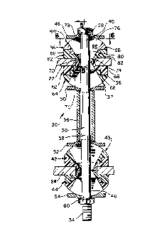
FIGURE 1 is an elevational view of an end link incorporating
features of the present invention fully assembled and embracing
portions of a stabilizer bar and a control element, portions of
which are shown in cross-section.
FIGURE 2 is an exploded side elevational view of the end link
shown in FIGURE 1.
FIGURE 3 is a cross-sectional view of the end link shown in a
first position.
FIGURE 4 is a cross-sectional view of the end link shown in a
second, pivoted position and taken generally along line 4 - 4 in
FIGURE 7.
FIGURE 5 is a partial cross-sectional view taken along line
5 - 5 in FIGURE 3.
FIGURE 6 is a plan view of the end link taken along line 6 - 6
in FIGURE 3.
FIGURE 7 is a plan view of the end link partially broken away
taken along line 7 - 7 in FIGURE 4 and without the head or washer
at the top of the end link.
3
214017
DETAILED DESCRIPTION OF THE PREFERRED EMBODIMENT
While the invention may be susceptible to embodiment in
different forms, there is shown in the drawings and herein will be
described in detail, a specific embodiment with the understanding
that the present disclosure is to be considered an exemplification
of the principles of the invention and is not intended to limit the
invention to that as illustrated and described herein.
An end link 20 incorporating features of the present invention
is shown in the drawings. The end link 20 is adapted to be
assembled with first and second elements, for example, a torsion or
stabilizer bar 22 and a control arm or element 24 of a vehicle
suspension of known construction. The first and second elements 22
and 24 are preferably made of metal.
In the embodiment shown, the end link 20 includes an elongated
connecting member or bar 26, which may be in the form of a bolt
having an abutment or a head 28 at one end thereof or a stud having
opposite threaded ends for receiving nuts (not shown). An
elongated rod or shank 30 extends axially from the head 28 and
includes an unthreaded portion 32 having a predetermined diameter
and a threaded end portion 34.
As shown in FIGURE 1, a first pair of grommets 36, 38, or
first and second portions, which will be described in detail
herein, is assembled generally at a first end 40 of the bolt 26, in
a manner described in detail herein. The grommets 36, 38 combine
to provide a first ball member 37 which embraces the suspension
element 22. A second pair of grommets 42, 44, or first and second
portions, is assembled generally at a second end 46 of the bolt 26.
The grommets 42, 44 combine to provide a second ball member 43
which embraces the suspension element 24.
Washers 48, 50, 52, 54 engage the outermost extents of the
grommets 36, 38, 42, 44 as described more fully in detail herein.
A spool or spacer 56 is mounted on an intermediate portion 58 of
the bolt 26 between the innermost grommets 38, 42 and engages the
innermost washers 50, 52. The spacer 56 supports the innermost
4
214014
grommets 38, 52 thereby maintaining the desired spacing between the
first element or stabilizer bar 22 and the second element or
control element 24. A nut 60 is applied to the threaded end
portion 34 of the bolt 26 for maintaining the parts in assembled
relationship. Outermost washer 54 is disposed between the nut 60
and the outermost grommet 44. Outermost washer 48 is disposed
between the head 28 and the outermost grommet 36.
The pairs of grommets 36, 38 and 42, 44 will be described in
detail with respect to the first pair of grommets 36, 38 which
combine to form the first ball member 37, with the understanding
that the second pair of grommets 42, 44 which combine to form the
second ball member 43, is identical in construction except that the
second pair of grommets 42, 44 engages the control element 24.
Referring now to FIGURE 2, it is seen that each grommet 36, 38
is comprised of first and second sections, a washer 62 and a
bushing 64. The washer 62 and bushing 64 are interengaged with
each other and are relatively rotatable with respect to each other
in response to universal movement between the rod 30 and the ball
members 37, 43 as described more in detail hereinbelow. The washer
62 and bushing 64 are made of suitable materials, preferably hard
plastic, for reasons described herein.
Each washer 62 has an annular body portion 66 which defines a
first end 68 and a protruding generally cylindrically shaped
shoulder 70 which defines a second end 72. Each end 68, 72 has a
circular aperture formed therein and the washer 62 has a central
passageway 74 therethrough which is generally conically shaped such
that the passageway 74 generally tapers from the first end 68 to
the second end 72. The aperture at the second end 72 of the washer
62 is of a predetermined diameter which is larger than the diameter
of the rod 30 so as to allow the rod 30 to pivot with respect to
the washer 62.
Each bushing 64 includes an arcuate or partially spherical
body portion 76 which defines a first end 78 and a protruding
portion 80 extending therefrom which defines a second end 82. The
5
2144174
bushing 64 may include ribs 84 to reinforce and strengthen the
arcuate body portion 76.
A straight, elongated slot 86, as best shown in FIGURES 6 and
7, is formed in the first end 78 of the bushing 64 and promotes the
pivoting of the rod 30 with respect to the ball members 37, 43 as
described hereinbelow. The slot 86 extends generally along the
entire arc of the arcuate portion 76.
The bushing 64 further includes a central passageway 88
therethrough which commences at the straight slot 86 at the first
end 78 of the bushing 64 and terminates at the second end 82 of the
bushing 64. The passageway 88 includes four surfaces or walls 90,
92, 94, 96 with the side surfaces or walls 90, 92 being generally
vertical and the end surfaces or walls 94, 96 tapering from the
first end 78 of the bushing 64 to the second end 82 at an angle
similar to that of the conical passage 74. The slot 86 and
associated passageway 88 have a width which is approximately equal
to the diameter of the rod 30. When the washer 62 and bushing 64
are interengaged as described below, the washer passageway 74 and
the bushing passageway 88 are aligned to form a passageway 74, 88,
which has a cross-section, as best shown in FIGURES 3 and 4, that
tapers from the bushing first end 78 to the washer second end 72.
To interengage the washer 62 and the bushing 64, the
protruding portion 80 of the bushing 64 is snapped into and is held
securely within a complementarily shaped recess 98 generally at the
first end 68 of the washer 62. The washer 62 includes a shoulder
or annular rib 100 interengageable with a complementary shoulder 80
on the bushing 64 whereby the washer 62 and bushing 64 are securely
held together. With this configuration, the washer 62 and bushing
64 simply snap together to form the completed grommet 36 or 38
while permitting the washer 62 and bushing 64 to freely rotate
relative to each other. It is to be understood that other
interengaging structures are within the scope of the invention so
long as the washer 62 and bushing 64 are able to freely rotate
relative to each other. For example, a hook shaped boss may be
6
214fl1'l4
formed on the bushing with a complementarily shaped recess in the
washer.
The bottom surface 102 of the bushing 64 and the top surface
104 of the washer 62 provide bearing surfaces along which the
washer 62 and bushing 64 may rotate with respect to each other.
These bearing surfaces 102, 104 are generally smooth and so as to
allow the parts to rotate easily relative to each other. Since the
washer 62 and bushing 64 are preferably made of plastic, a desired
ease of rotation between these parts can be achieved by modifying
the coefficient of friction of the plastic material used. For
example, nylon may be used to produce the washer 62 and the bushing
64 may be made of acetal copolymer or acetal homopolymer.
To form the grommets 36, 38 and 42, 44 which are disposed on
each end 40, 46, respectively, of the bolt 26, the washer 62 and
the bushing 64 are interengaged, as described above, to form a
completed grommet 36, 38 and 42, 44. The second ends 72 of each of
the washers 62 are placed in an abutting relationship to form the
ball members 37 and 43. The stabilizer bar 22 or control element
24 is held between the washers 62. It is to be understood that the
coefficient of friction of the plastic washer 62 is sufficiently
related to the coefficient of friction of the metal stabilizer bar
22 or the metal control element 24 such that the ball members 37
and 43 generally do not rotate relative to the elements 22, 24
which prevents undue wear of the washers 62. The rod 30 is
disposed within the aligned passageways 74, 88 of each grommet 36,
38 and 42, 44.
The washers 48, 50, 52, 54 which engage the outermost extents
of each grommet 36, 38 and 42, 44, respectively, include a seat 106
that is complementarily shaped to the arcuate portion 76 of the
bushing 64. The washers 48, 50, 52, 54 are formed from a suitable
material, preferably metal, such as steel and the seat 106 may be
formed by any suitable known method, such as stamping or coining.
When a washer 48, 50, 52 or 54 is disposed on the arcuate portion
76 of the bushing 64, the washer 48, 50, 52 or 54 is free to travel
7
2~4~174
along the arc of the arcuate portion 76 when there is relative
movement between the stabilizer bar 22 and the control element 24.
Each washer 48, 50, 52, 54 also includes a circular aperture 108
generally in the center thereof to allow the rod 30 to pass through
the washer 48, 50, 52, 54.
Now that the specifics of the end link 20 have been described,
a general description of how the end link 20 operates will be
explained. Initially, the bolt 26 extends generally
perpendicularly between the first element or stabilizer bar 22 and
the second element or control element 24, as shown in FIGURE 3 and
as shown in FIGURE 6, sits generally in the center of the ball
member 37.
When an input load is incurred, the rod 30 begins to move or
pivot along a single plane in the straight slot 86. When the rod
30 pivots, the seat 106 of each washer 48, 50, 52, 54 slides along
the arc of the arcuate portion 76. Since the aligned passageway
74, 88 is tapered, the rod 30 is free to pivot plus or minus 30°
from the vertical position or some lesser or greater angle
determined by the slope of the passage 74, 88 surface.
In other words, connecting member 32 extends between first
element 22 and second element 24 with end member of grommets 36 on
the end of member 32 embracing first element 22. The end member 36
has a central vertical axis therethrough and its construction
provides means for permitting universal pivotal movement of the end
member 36 and for permitting positive and negative movement of the
connecting member 32 relative to the central vertical axis of the
end member only substantially in a single plane relative to the end
member.
As the rod 30 leaves the center of the slot 86 and as any
amount of side load is incurred, the rod 30 begins to push against
the vertical side wall 90 or 92 of the slot 86. This force results
in a moment about the center of the bushing 64 causing a.t to rotate
relative to the washer 62 as shown in FIGURES 4 and 7. The rod 30
can universally pivot generally around the center of each ball
21 40 1 7Q~
member 37, 43, that is, move 360° conically by this pivoting on
each end of the end link 20.
Since the rod 30 passes directly through ball members 37 and
43 which are respectively provided by the grommets 36, 38 and 42,
44, loads are directly transmitted through the grommets 36, 38 and
42, 44. This allows a lighter torsion bar to be used.
Furthermore, since the end link 20 is comprised of few parts and is
easily assembled, the end link 20 may be economically produced.
While a preferred embodiment of the present invention is shown
and described, it is envisioned that those skilled in the art may
devise various modifications of the present invention without
departing from the spirit and scope of the appended claims. The
invention is not intended to be limited by the foregoing
disclosure.
9