Language selection

Search

Patent 2140391 Summary

Third-party information liability

Some of the information on this Web page has been provided by external sources. The Government of Canada is not responsible for the accuracy, reliability or currency of the information supplied by external sources. Users wishing to rely upon this information should consult directly with the source of the information. Content provided by external sources is not subject to official languages, privacy and accessibility requirements.

Claims and Abstract availability

Any discrepancies in the text and image of the Claims and Abstract are due to differing posting times. Text of the Claims and Abstract are posted:

  • At the time the application is open to public inspection;
  • At the time of issue of the patent (grant).
(12) Patent Application: (11) CA 2140391
(54) English Title: STRAW TIP
(54) French Title: POINTE DE PAILLE
Status: Deemed Abandoned and Beyond the Period of Reinstatement - Pending Response to Notice of Disregarded Communication
Bibliographic Data
(51) International Patent Classification (IPC):
  • A47G 21/18 (2006.01)
  • A47G 19/22 (2006.01)
  • B65D 47/24 (2006.01)
(72) Inventors :
  • BARNWELL, KEITH D. (Canada)
(73) Owners :
  • LIFOAM OF CANADA INC.
(71) Applicants :
  • LIFOAM OF CANADA INC. (Canada)
(74) Agent: BLAKE, CASSELS & GRAYDON LLP
(74) Associate agent:
(45) Issued:
(22) Filed Date: 1995-01-17
(41) Open to Public Inspection: 1996-07-12
Examination requested: 1995-01-17
Availability of licence: N/A
Dedicated to the Public: N/A
(25) Language of filing: English

Patent Cooperation Treaty (PCT): No

(30) Application Priority Data:
Application No. Country/Territory Date
08/371,100 (United States of America) 1995-01-11

Abstracts

English Abstract


A straw for a drinking container that is self-ventilating
and self-sealing. The straw has two parts, a straw tip and a
straw cover. The cover is retained on the straw tip and is
movable by manual pressure between a closed position and an
open position. The tip has a solid closed top and an open
bottom to allow for a straw extension piece to extend into the
container for drawing liquid up into the straw. The straw is
self-sealing in that a hole in the cover through which a user
would suck is sized to sealingly fit the end of the tip in the
closed position. In addition, the cover and tip are sealed at
the open bottom in the closed position and drainage holes in
the tip allow any liquid that falls between the cover and the
tip to flow back into the container. The tip has an abutment
surface around its perimeter between holes that release liquid
in the user's mouth and holes that allow for air intake. The
straw is self ventilating in that when the cover, which is
attached to the tip just above the abutment surface, is moved
to the open position, ridges on the inner surface of the cover
grasp the tip's surface at certain points so as to
automatically allow air into the container to draw out liquid,
while at the same time preventing air from entering the user's
mouth.


Claims

Note: Claims are shown in the official language in which they were submitted.

THE EMBODIMENTS OF THE INVENTION IN WHICH AN EXCLUSIVE
PROPERTY OR PRIVILEGE IS CLAIMED ARE DEFINED AS FOLLOWS:
1. A straw for a drinking container comprising:
(i) a tip having an internal channel terminating at
a solid closed top and an open bottom and at
least one first hole for liquid egress through
the side of the tip into the channel and having
at least one second hole through the side of
the tip into the channel for air intake lower
than the first hole;
(ii) an abutment surface of the tip around the
outside of the perimeter of the tip between the
first hole and the second hole;
(iii) a hollow cover movably retained on the tip
and surrounding the tip having a hole at
its upper end sized to fit around the
solid top of the tip in sealing engagement
when in a first closed position and in
disengagement when in a second opened
position so as to allow liquid to be
removed in such second position;
(iv) a first ridge on an inner surface of the cover
which is sized to sealingly engage the abutment

surface between the first and the second hole
when in the second open position; and
(v) a second ridge on an inner surface of the cover
below the first ridge which is sized to
sealingly engage the tip below the second hole
when in the first closed position and which
disengages from the tip when in the second open
position so as to allow air into the second
hole in such second position.
2. The straw of claim 1, wherein a straw extension is
sealingly attached to the open bottom of the tip and extends
downwardly to reach a liquid in the container.
3. The straw of claim 1, wherein the straw is part of a
closure cap for a drinking container.
4. The straw of claim 1 wherein the tip has a third
hole through the side of the tip into the channel located
between the first hole and the abutment surface.
5. The straw of claim 4 wherein any of the first,
second or third holes are a plurality of holes spaced around
the perimeter of the tip.
6. The straw of claim 5 in which the tip and cover are
cylindrical.

7. The straw of claim 1 in which the abutment surface
extends around the entire outside perimeter of the tip and the
first ridge extends around the entire inside perimeter of the
cover.
8. The straw of claim 7 in which the second ridges
extend around the entire inside perimeter of the cover.

Description

Note: Descriptions are shown in the official language in which they were submitted.


2140391
-
1 --
This invention relates to straws for containers that hold
liquids for drinking. In particular, this invention relates
to a self-ventilating and self-sealing straw tip and straw tip
cover for a drinking container which is attached to a closure
cap for the container. The straw tip is self-ventilating in
its open position and self-sealing in its closed position and
also has means for draining fluid back into the container.
A number of straws are known that provide venting means
and sealing means.
United States Patent No. 4,448,316 shows a bottle
containing a spring loaded straw. When the bottle cap is open
the straw pops out and the venting action is provided directly
around the body of the straw.
United States Patent No. 4,966,300 shows a drinking
container having two straw portions. The iower straw portion
is fixed in position and the upper straw portion is movable
between a down storage position and an up in-use position.
When the upper straw is pulled upwardly, it opens the liquid
path from the container. When the upper straw is pushed back
down, it closes the liquid path. A separate vent is provided
through the cap and this vent is open and closed by the
closure cap not by movement of the upper straw.

214~391
-
-- 2
United States Patent No. 5,048,705 shows a cap with a
centre straw and a separate side vent open independently of
the straw.
Unites States Patent No. 3,173,566 shows a container with
a vertically movable straw and a vent which is opened and
closed by means of a rotating cap on the container.
United States Patent No. 4,909,408 describes a specific
venting structure but does not describe a straw or spout
movable in combination with a vent.
The present invention provides, in a first aspect, a
straw for a drinking container, having a tip with (a) an
internal channel terminating at a solid closed top and an open
bottom, (b) at least one first hole for liquid egress through
the side of the tip into the channel and (c) at least one
second hole through the side of the tip into the channel for
air intake lower than the first hole. The tip has an abutment
surface around the outside of the perimeter of the tip between
the first hole and the second hole. The straw has a hollow
cover movably retained on the tip and surrounding the tip, the
cover having a hole at its upper end sized to fit around the
solid top of the tip in sealing engagement when in a first
closed position and in disengagement when in a second opened
position so as to allow liquid to be removed in such second
position. A first ridge on an inner surface of the cover is
sized to sealingly engage the abutment surface of the tip when

2140391
-- 3
in the second open position. A second ridge on an inner
surface of the cover below the first ridge sealingly engages
the tip below the second hole when in the first closed
position and disengages from the tip when in the second open
position so as to allow air into the second hole in such
second position.
The straw may include a straw extension which is
sealingly attached to the open bottom of the tip and extends
downwardly to reach a liquid in the container.
The straw may be part of a closure cap for a drinking
container.
The tip may have a third hole through the side of the tip
into the channel located between the first hole and the
abutment surface.
Any of the first, second or third holes may be a
plurality of holes spaced around the perimeter of the tip.
The tip and cover may be cylindrical.
The abutment surface may extend around the entire outside
perimeter of the tip and the first ridge may extend around the
entire inside perimeter of the cover.

_ 4
The second ridges may extend around the entire inside
perimeter of the cover.
For a better understanding of the present invention and
to show more clearly how it may be carried into effect,
reference will now be made by way of example to the
accompanying drawings, which show an apparatus according to
the preferred embodiment of the present invention and in
which:
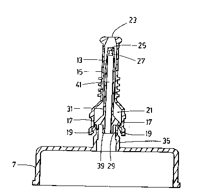
Figure 1 is an exploded perspective view of a straw
according to the preferred embodiment of the present invention
shown with a closure cap, a straw extension and a drinking
container.
Figure 2 is a side elevation of the straw and the closure
cap of Figure 1.
Figure 3 is a cross-section of the straw and the closure
cap of Figure 2 shown in a closed position and taken along
lines 3-3.
Figure 4 is a cross-section of the straw and the closure
cap of Figure 2 shown in open position and taken along lines
3-3.
Referring to Figure 1, there is shown a drinking
container 1 which is normally designed to hold a cold or hot

214~391
-- 5
liquid and is therefore surrounaed by a thermally insulated
outer layer 3. Container 1 has threads 5 on which is screwed
a closure cap 7. Attached to the closure cap is a straw 9
having two parts (not shown in Figure 1), a straw tip and a
straw cover, to be described further later.
The straw has connected to it a straw extension piece 11
which extends from the straw on underside of the closure cap 7
into the container 1 for drawing liquid up into straw 9.
The closure cap and straw are shown in more detail in
Figure 2.
In Figure 3, a cross-section taken along the lines 3-3 in
Figure 2, the closure cap 7 and the straw tip 13 are moulded
from a single piece so that the straw tip 13 extends upwardly
from the closure cap 7. While shown as a single moulded
piece, it is possible for the straw tip 13 to be screwed onto
the closure cap or in any other way attached to the closure
cap in a sealing engagement. Straw tip 13 has cover 15
retained on it.
Cover 15 is movable by manual pressure between a closed
position shown in Figure 3 and an open position shown in
Figure 4.
Cover 15 contains a hole 23 through which a user would
suck to create a vacuum. The end 25 of tip 13 is solid and is

, 2I~0391
sized to fit snugly and in sealing engagement into hole 23
when the cover 15 is in the closed position as shown in Figure
3. Tip 13 also contains holes 27 (only one of which is
visible) along the side of thé tip through which liquid can be
pulled by the action of the vacuum created by the user at hole
23.
The maximum extension of upward travel of cover 15 is
limited by abutment surface 17 which extends around the
periphery of tip 13 and which contacts ridge 19 which also
extends around the periphery of the inner surface of cover 15.
In addition to preventing removal of cover 15 from tip 13,
ridge 19 seals against the abutment surface 17 to limit air
from entering into cavity 21 when a partial vacuum is created
in the straw channel 41 and cavity 21 by the sucking action of
a person at the end of the straw at hole 23.
In assembly, straw cover 15 must be press-fit over straw
tip 13. Ridges 17 and 19 are designed as "one-way" tapers to
allow for assembly, yet through normal use will not disengage.
Tip 13 also contains holes 29 which communicate into the
interior of the container 1 through the closure cap 7, so that
when liquid is evacuated through holes 27 and 23 into the
mouth of the user, air can enter the container to replace the
liquid removed by the user through sucking.

~l~o39l
-- 7
Because there is a seal between abutment surface 17 and
ridge 19, air is generally drawn into the container and not
into cavity 21 and into the mouth of the user. Additional
holes 31 are contained on the straw tip 13 for removal of
excess liquid in the cavity 21 after the user has stopped
sucking on straw 9. These holes help prevent liquid pressure
from building up in cavity 21 when cover 15 is closed, as any
excess liquid in cavity 21 will strain into the container
through holes 31. As the holes 31 are contained in cavity 21
above the seal created by abutment surface 17 and 19 (when in
the open position), air is not easily drawn into the straw
through holes 31 when the user sucks at hole 23.
The cover 15 also contains a second ridge 33 which, in
the closed position as shown in Figure 3, abuts the base of
the tip along sealing surface 35 so that the cover is sealed
to the base below hole 29. An additional ridge may be
provided near ridge 33, to touch surface 35 and provide an
additional seal at the base of straw 9. In addition, ridge 19
may also touch the base of the tip to provide an additional
measure of sealing between the tip 13 and the cover 15.
When in the closed position as shown in Figure 3, end 25
of tip 13 acts as a stopper completely filling hole 23 to
sealingly stop liquid from exiting through hole 23.

2140391
-- 8
Thus, in the closed position cavity 21 is entirely sealed
both at the top by end 25 of tip 13 in hole 23 and at the
bottom by ridges 19 and 33 abutting sealing surface 35.
As can be seen in Figures 3 and 4, the base of the tip 13
is not of uniform diameter. The sealing surface 35 is of a
larger diameter than space 37 immediately below abutment ridge
17, so that when the cover is drawn to the open position shown
in Figure 4, neither ridge 33 nor ridge 19 contact the base of
tip 13 so as to allow air to enter into hole 29 as previously
described.
Tip 13 also contains end 39, the interior of which is
adapted so that straw extension 11 (shown in Figure 1) can be
fitted into end 39 to create a continuous internal channel
through straw extension 11 and up through channel 41 through
holes 27 and 23 so that liquid can exit the container under a
vacuum created by a user sucking on straw cover 15.
The tip, cover, container and closure cap are preferably
made of plastic or other non-breakable material. The tip and
cover are preferably cylindrical in shape but could be made of
any matching size and shape.
This description is made with reference to the preferred
embodiment of the invention. However, it is possible to make
other embodiments that employ the principles of the invention

4o39l
- 9
and that fall within its spirit and scope as defined by the
following claims.

Representative Drawing
A single figure which represents the drawing illustrating the invention.
Administrative Status

2024-08-01:As part of the Next Generation Patents (NGP) transition, the Canadian Patents Database (CPD) now contains a more detailed Event History, which replicates the Event Log of our new back-office solution.

Please note that "Inactive:" events refers to events no longer in use in our new back-office solution.

For a clearer understanding of the status of the application/patent presented on this page, the site Disclaimer , as well as the definitions for Patent , Event History , Maintenance Fee  and Payment History  should be consulted.

Event History

Description Date
Inactive: IPC from MCD 2006-03-11
Application Not Reinstated by Deadline 2000-10-06
Inactive: Dead - Final fee not paid 2000-10-06
Deemed Abandoned - Failure to Respond to Maintenance Fee Notice 2000-01-17
Deemed Abandoned - Conditions for Grant Determined Not Compliant 1999-10-06
Notice of Allowance is Issued 1999-04-06
Letter Sent 1999-04-06
Inactive: Status info is complete as of Log entry date 1999-03-29
Inactive: Application prosecuted on TS as of Log entry date 1999-03-29
Inactive: Approved for allowance (AFA) 1999-03-01
Application Published (Open to Public Inspection) 1996-07-12
All Requirements for Examination Determined Compliant 1995-01-17
Request for Examination Requirements Determined Compliant 1995-01-17

Abandonment History

Abandonment Date Reason Reinstatement Date
2000-01-17
1999-10-06

Maintenance Fee

The last payment was received on 1999-01-07

Note : If the full payment has not been received on or before the date indicated, a further fee may be required which may be one of the following

  • the reinstatement fee;
  • the late payment fee; or
  • additional fee to reverse deemed expiry.

Patent fees are adjusted on the 1st of January every year. The amounts above are the current amounts if received by December 31 of the current year.
Please refer to the CIPO Patent Fees web page to see all current fee amounts.

Fee History

Fee Type Anniversary Year Due Date Paid Date
MF (application, 3rd anniv.) - standard 03 1998-01-20 1998-01-16
Registration of a document 1998-11-24
MF (application, 4th anniv.) - standard 04 1999-01-18 1999-01-07
Owners on Record

Note: Records showing the ownership history in alphabetical order.

Current Owners on Record
LIFOAM OF CANADA INC.
Past Owners on Record
KEITH D. BARNWELL
Past Owners that do not appear in the "Owners on Record" listing will appear in other documentation within the application.
Documents

To view selected files, please enter reCAPTCHA code :


To view images, click a link in the Document Description column. To download the documents, select one or more checkboxes in the first column and then click the "Download Selected in PDF format (Zip Archive)" or the "Download Selected as Single PDF" button.

List of published and non-published patent-specific documents on the CPD .

If you have any difficulty accessing content, you can call the Client Service Centre at 1-866-997-1936 or send them an e-mail at CIPO Client Service Centre.


Document
Description 
Date
(yyyy-mm-dd) 
Number of pages   Size of Image (KB) 
Claims 1999-02-16 3 67
Description 1996-07-11 9 249
Abstract 1996-07-11 1 33
Drawings 1996-07-11 4 40
Claims 1996-07-11 3 61
Representative drawing 1997-12-11 1 8
Courtesy - Certificate of registration (related document(s)) 1998-12-21 1 114
Commissioner's Notice - Application Found Allowable 1999-04-05 1 164
Courtesy - Abandonment Letter (NOA) 1999-12-08 1 171
Courtesy - Abandonment Letter (Maintenance Fee) 2000-02-13 1 185
Fees 1999-01-06 1 34
Fees 1998-01-15 1 38
Fees 1996-12-19 1 45
PCT Correspondence 1995-03-26 1 15
Courtesy - Office Letter 1995-06-12 1 9
Courtesy - Office Letter 1995-03-05 1 10
Courtesy - Office Letter 1995-07-31 1 23
Examiner Requisition 1998-07-30 2 24
Prosecution correspondence 1999-01-22 1 24