Note: Descriptions are shown in the official language in which they were submitted.
21~04~1
EXTRUDED BUILDING AND METHOD AND APPARATUS RELATED TO SAME
BACKGROUND OF THE INVENTION
The present invention generally concerns building structures, and more specifically
concerns a building structure made from a large extrusion of polymeric material which facili-
5 tates m~nllf~ctllre of the building structure while advantageously m~int~ining the appearanceof conventional wood frame residential housing. The present invention further concerns a
method and a~alalus for m~nllf~ctllring the building structure.
A number of building structures have been proposed for making low cost affordable
housing. However, t-h-e known low cost building structures usually look "low cost" and lack
10 ~çsth~tir appeal, making them lm~ttr~tive to tenants. The known building structures can be
made more attractive by customizing the building structure on-site; however, on-site
cu~lollli~lion is not "low cost" since it requires use of skilled labor on-site. Also, additional
features facilit~tin~ on-site construction and/or cu~Lollli~dlion of the building structure are
desired. At the same time, improvements yielding greater mass production efficiencies are
15 desired.
Some low cost structures use cement as the load bearing structural material. Forexample, in U.S. Patent 2,691,291 (to Henderson) there are disclosed multiple precast con-
crete segments that can be assembled to form a building structure. However, prefabricated
cement segments are cast, which is a batch type process requiring multiple forms and
20 Co~ "~ g con~ hle time while the cement cures. Further, the segments are solid
concrete, making them heavy even if they are only a few feet long. For example, Henderson
discloses that the segments must be made relatively short in length to avoid segments that are
"too large or unwieldy". (See Henderson, column 1, lines 13-14). It is noted that the short
length makes the on-site assembly tedious since not only must multiple pieces be carefully
25 ~lign~l, but also equipment for manipulating the heavy segments must be present on-site.
Still further, concrete is not always the material of choice. For example, concrete is
thermally conductive, and thus has a poor energy efficiency making it less desirable in cold
c~imates. Still further, precast and uncovered concrete tends to have a cold, "uninviting"
~_ `` 21404~i
appearance that is very di~clcllL from conventional wood frame residential housing. This
often makes the bl1ilding~ unacceptable to tenants, unless substantial work is pelr~,lllled on-
site to customiæ the building. However, the on-site customization is costly, as noted above.
Additionally, it is noted that it is very difficult to make on-site modifications and/or
5 customizations in the cement structure, such as the addition of windows or doors, since the
walls and roof are solid concrete.
In U.S. Patent 3,923,436 (to Lewis) there is disclosed an elongated building structure
m~nllf~rtllred on-site from foamed-in-place material. The load bearing material of the
building structure is the foamed-in-place material, which must be made strong enough to
10 with~t~n-l the stresses and abuse encountered by a typical building. Lewis notes that it may
be desirable to increase the durability and tol~ghnPss of the exterior skin of the foamed-in-
place material, and for this purpose Lewis discloses that surfacing material may optionally
be added to the inside and/or outside of the foamed-in-place material (see column 3, lines 18
et seq). However, even with the addition of the surfacing material, the foamed-in-place
15 material forms substantially the entire load bearing portion of the building structure. Lewis
does not suggest constructing a load bearing wall section having structurally stiff layers at
the inner and outer surfaces which, from an engineering standpoint, is where the load bearing
structure is most nPede~l Further, in Lewis there are no flanges on the surfacing material
that facilitate fini~hing the building structure, nor are there any features on the surfacing
20 material or on the foam material of the wall that facilitate installation onto a foundation.
Also, it is noted that the foamed structure in Lewis is substantially limited to on-site
fabrication since the foam has a poor tensile ~LlcngLll and may crush or break if impacted or
bent, such as often happens during shipping. However, on-site fabrication is expensive,
difflcult to control, and does not take m~ximum advantage of mass production. Still further,
25 even with the addition of surfacing material to the foamed-in-place material in Lewis, the
long term durability of the building walls is potentially not as good as desired.
In regard to the appaldLus and method disclosed in Lewis, Lewis teaches use of am~ in~ including a foaming device and adjustable forms which can be used on-site.
2140~1
~,
However, such equipment tends to be cumbersome to use, is expensive to ship, and requires
skilled labor to safely operate. Further, the a~aldlus requires use of hazardous materials
on-site, such as isocyanate material in the case of polyurethane foam. Still further, it is
noted that the appaldLus is not productive during transport or setup, and further is subject to
v~n~ m while on-site, thus making the overall cost higher than may initially be appal~
As a practical matter, it is noted that the sidewalls of a foam structure made by the Lewis
m~rhin~ may tend to bulge or wander as the structure is being formed or as the foam is
curing, thus leading to later complaints from tenants about the building quality. This is a
difficult problem since the building is constructed on-site where there is less than optimal
quality control. Lewis also suggests that the machine can be used to m~nllf~r.ture a building
structure including a floor (column 6, lines 62 et seq). However, any such floor structure
would require continuous support until the floor cured to a self-supporting state, which would
be a slow and tedious process for foamed-in-place material or cement, and thus which is not
conducive to mass production.
It is noted that the Lewis patent also discloses that cement can be used instead of
foamed-in-place materials, however this produces a building structure having limitations not
unlike those disclosed in Henderson, which were discussed above.
Thus, a building structure and method and appal~lus for m~nllf~cturing same solving
the aforementioned problems are desired.
SUMMARY OF THE INVENTION
In one aspect, the present invention includes a building structure comprising anelongated tubular extrusion including integral wall sections r.~ hlg a floor, sidewalls, and
a roof. The wall sections define an interior space large enough for a person to comfortably
stand in, with the wall sections defining the floor and the sidewalls being generally planar
and orthogonally related to each other, and further the wall section defining the roof having
an inclined surface so that the extrusion has the shape and appe~ranre of a conventional wood
frame residential building. The wall sections include at least one layer of non-foamed
polymeric material forming a load bearing structural part of the wall section.
~ .
21~04~1
In another aspect, the present invention includes a building structure comprising an
elongated extrusion including integral wall sections forming sidewalls and a roof, the wall
section defining an interior space large enough for a person to stand in. The wall sections
of a first layer and a second layer, the first layer being structural non-foamed polymeric
5 material and the second layer being one of lcil~l-;ement webs integrally extending from the
first layer and a slab of rigid foam bonded to the first layer. In one aspect, the wall sections
comprise inner and outer layers of non-foamed structural polymeric material bonded to and
spaced apart by an interm~ te layer of foam material.
The plcrcllcd embodiments disclosed herein include several advantages over known10 prior art. The extruded building construction having a tubular shape has the rigidity,
structure and leak proof shape of a tube. Further, the extruded wall sections have a high
strength and durability due to the inner and outer layers of structural polymeric materials
which are supported by an intermediate layer of rigid foam and/or reinforcement webs. Still
further, the inner and outer layers can include multiple features "as-molded", such as
15 molded-in color (including different colors between the sidewalls and the roof, and di~clcllL
colors between the inner and outer surfaces), dilIelcnl surface textures and pattcrns on all
surfaces, molded-in mounting flanges and other flanges facilitating installation of secondary
components, and properties of light weight and high ~lcngLIl-to-weight ratio facilit~ting
shipment and on-site in~t~ tion. Unlike other known products and processes, the present
20 invention aims to provide a "user friendly" product which sim~ tes conventional wood frame
residential construction while siml-lt~n~-ously providing advantages of permanent color,
moisture resistance, low air infiltration, high energy efficiency, and dramatically lower total
cost after assembly and in~t~ tion. Notably the extruded structure of the present invention
can be extruded in any length desired, and the ends of the extruded structure can be cut to
25 mate with other building structures. Further, the wall sections of the extruded home can be
modified on-site with conventional hand tools such as with a skill saw or the like, yet are
durable enough to with~t~n(l typical wear and tear on the exterior of a building. Still further,
the low weight and high ~ sLh-to-weight ratio permit the extruded building structure to be
21~0421
, , ,
m~nllf~rt~lred at a central location for m~ximum mass production advantage, but permit the
building structure to be readily shipped over roads and highways. Still further, the extruded
home is compatible with a "co~ uLer integrated m~,k~ and m~mlf~hlring process" in
which a mass produced but customer tailored high quality building can be provided. For
5 example, the colll~uL~l int~gr~ted m~krti~g and m~nllf~rtllring process allows the customer's
applvv~d order to be lliln.~ iLI~d by modem directly to the com~uL~l driven m~mlf~ctllring
processes and machinery. Notably, the extruded building unit itself is structurally whole,
elimin~ting the need for a structural frame (such as is required in mobile homes).
These and other features, advantages, and objects of the present invention will be
10 further understood and appreciated by those skilled in the art by reference to the following
specification, claims, and appended drawings.
BRIEF DESCRIPTION OF THE DRAWINGS
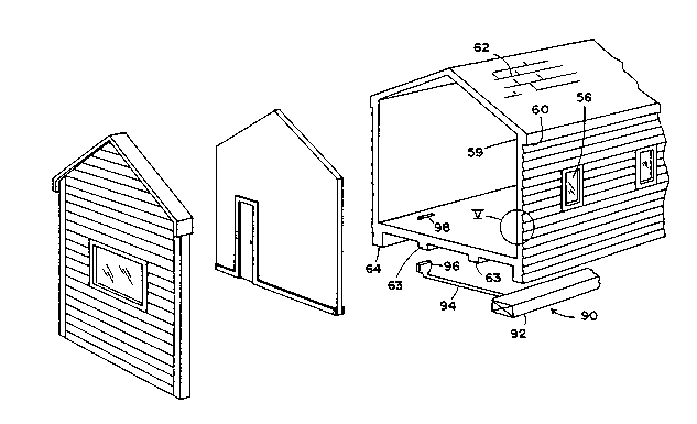
Fig. 1 is a perspective view of a building structure embodying the present invention,
the building structure including a tubular extrusion with wall sections defining sidewalls, a
15 roof, and a floor, and further including end walls (only one of which is shown)for closing
the ends of the tubular extrusion, and an intermediate wall for subdividing interior space of
the tubular extrusion;
Fig. 2 is an end view of the building structure shown in Fig. l;
Fig. 3 is a side view of the building structure shown in Fig. 1 but including both end
20 walls;
Fig. 4 is an exploded, perspective view of the building structure shown in Fig. 1,
including an end wall, an intermediate wall, a main building extrusion, and a forced air heat
duct assembly;
Fig. 5 is an enlarged, fragmentary side cross-sectional view of the circled area V-V
25 in Fig. 4;
Figs. 5A and 5B are fragmentary side views of two alternative wall sections having
di~l~nl exterior surfaces;
` 2140~1
Fig. 6 is an enlarged, fragmentary cross-sectional view of the building structure rested
on and joined to a foundation;
Figs. 7-9 are enlarged, fragmentary cross-sectional views of alternative modified
extruded building structures rested on and joined to a foundation;
Fig. 10 is an enlarged, fragmentary cross-sectional view of the circled area X in
Fig. 1 showing a baseboard at the corner defined by the floor and sidewall;
Fig. 11 is a side elevational view of the interm~ te wall shown in Figs. 1 and 4;
Fig. 12 is a cross-sectional view taken along the plane XII-XII in Fig. 11 showing the
baseboard at the corner defined by the intermediate wall and the floor;
Fig. 13 is a cross-sectional view taken along the plane XIII-XIII in Fig. 11 showing
the door casing and doorway opening;
Fig. 13A is a cross-sectional view comparable to Fig. 13 but showing an alternative
door casing construction;
Fig. 14 is a fragmentary cross-sectional view of an end corner of the building
lS structure taken along the plane XIV-XIV in Fig. 3;
Fig. 14A is a fragmentary cross-sectional view comparable to Fig. 14 but of an end
corner of an alternative construction;
Fig. 15 is an end view of a modified extruded building structure embodying the
present invention, the modified building structure including enlarged beam-like structures for
en~ging a transport trailer;
Fig. 16 is an end view of another modified building structure embodying the present
invention, the modified building structure being configured to form a double wide building
structure and including a field applied roof cap/cover plate;
Fig. 17 is a side view of the building structure shown in Fig. 1 on a transport trailer;
Fig. 18 is a cross-sectional view taken along the planes XVIII-XVIII in Fig. 17;Fig. 19 is a perspective view of a building structure embodying the present invention,
the building structure including a main extruded building structure configured to be used as
21404~1
~f
living quarters and an extruded garage structure attached to the main building structure by
an extruded blee;~w~y structure defining a three-season room;
Fig. 20 is a front view of the building structure shown in Fig. 19;
Fig. 21 is a plan view of the building structure shown in Fig. 19;
Fig. 22 is a plan view of a modified building structure embodying the present
invention, the building structure including a main extruded building structure configured to
be used as living quarters and an attached garage structure attached to the main building
structure by an extruded roof structure;
Fig. 23 is a cross-sectional view taken along the plane XXIII-XXIII in Fig. 22
showing the garage structure;
Fig. 24 is a cross-sectional view of a modified building structure generally similar to
that shown in Fig. 23 but including integral but discrete truss members;
Fig. 25 is a cross-sectional view of another modified building structure generally
similar to that shown in Fig. 23 but including non-unirollllly positioned discrete truss
members;
Fig. 26 is a side elevational view of the extruded breeæway roof structure shown in
Fig. 22;
Fig. 27 is an end view of the breeæway roof structure in Fig. 26; and
Figs. 28 and 29 are flow diagrams for a method of m~nllf~turing the extruded
building structures noted above.
DETAILED DESCRIPTION OF THE PREFERRED EMBODIMENTS
An extruded building structure 30 (Figs. 1-4) embodying the present invention
includes a one piece extruded and cut-to-length extrusion 32, including integral sidewalls 33
and 34, a roof 35, and a floor 36 defining an interior space 38. The sidewalls 33 and 34,
roof 35, and floor 36 include various flanges and other features to facilitate mass production
and shipping of the building structure while mi~ lli7.i~-g or simplifying secondary operations
such as attaching the building structure to a foundation and assembling fixtures and secondary
parts such as baseboards to the building structure. The extrusion 32 is configured to simulate
- I 21401~i
a quality conventional wood frame construction and allows a customer to select the siæ,
shape, and color of various parts of the structure while m~int~ining advantages including
pellllallell~ color, moisture resistance, low air infiltration, high energy efficiency, and
lr~m~ti~lly lower total costs. Building structure 30 further includes a pair of end walls 40
5 and at least one interm~di~te wall 42 for eng~ging extrusion 32 to subdivide the interior space
38 within extrusion 32.
The wall sections defining members 33-36 include an inner layer 44 and an outer
layer 46 spaced from inner layer 44 and interconn~ct~d to layer 44 by a supporting
intermediate layer of r~il~l~;ement webs 48 and rigid foam 50, such as is illustrated in Fig.
5. Inner layer 44 and outer layer 46 are comprised of non-foamed structural materials such
as thermoplastic polymeric materials chosen to provide load bearing structure to the wall
sections. Reinforcement webs 48 are integr~lly extruded with inner and outer layers 44 and
46. Reinforcement webs 48 stabiliæ layers 44 and 46 at locations of relatively high stress
along the wall sections, and at strategically located points, can include thicker sections to
provide additional support for attached items such as cabinets or doors. Further, inner and
outer layers 44 and 46 provide a very durable and long lasting surface that can withstand the
abrasion and wear required of a building structure. Notably, layers 44 and 46 can be
increased in thickness or otherwise shaped for added ~lell~Lh and/or aesth~qtirs as desired.
For example, outer layer 46 can be shaped to replicate clapboard or beveled siding (Fig. 5),
dutchlap siding 46' (Fig. 5A), or log-type wall construction 46" (Fig. 5B). It is also
contemplated that flanges can be extended inwardly from inner layer surface 45 into interior
space 38 or that layer 44 can be made thicker in certain areas to facilitate locating and
supporting baseboards, kitchen cabinets, and other building fixtures. Also, longit~ in~lly
extending bosses or apertured webs 49 can be positioned on webs 48, such as for receiving
a screw or fastener 58 for holding a door casing to a doorway opening (see Fig. 13A), as
li~c~lssed below.
Still further, the surfaces 45 and 47 of inner and outer layers 44 and 46 respectively
can be textured and colored as desired. For example, outer layer surface 47 can be colored
21404~
and textured to sim~ tP siding (e.g. al~ lll siding or wood siding) or a log home, while
inner layer surface 45 can be colored a di~el~llL color and textured to simulate drywall,
paneling or another surface. Still further, the inner and outer surfaces of any of sidewalls
33 and 34, roof 35 and floor 36 can be colored with di~l~llL colors selected by a customer.
5 The colors would be continuous throughout layers 44 and 46, and thus would be long lasting.
It is contemplated that the coloring could be efficiently and economically done as part of the
extruding process such as by adding colorant to the polymer feedstock being fed into the
extruding process. Also, additives resisting degradation from ultraviolet radiation could be
added to outer layer 46 as desired.
The extruded thermoplastic layers 44 and 46 and lch~l~;ement webs 50 quickly
solidify and become rigid after exiting the extruder and extruder die during the extrusion
process. Thus, immP(li~tP.ly after extruding layers 44 and 46 or at some time soon thereafter,
foam material 50 can be added to the wall section in the space between layers 44 and 46.
The inner and outer layers 44 and 46 contain the foam material 50 as it PYp~n~l~ As the
foam material solidifies/cures, the foam 50 securely bonds and interconnects layers 44 and
46 to form a rigid "stressed skin" structure having structural elements or "skins" spaced apart
by a rigid interconnPcting element in a beam-like manner. This stressed skin structure
positions structural "skin" portions of the wall section at the outer edges of the wall section
at an optimal position based on engineering principles for supporting loads.
It is contemplated that layers 44 and 46 and webs 48 will be about 1/8" thick, and
will be a structural plastic such as thermoplastic, although alternative materials and thickness
can be used. By use of these materials, the wall sections provide a rigid construction which
can be cut, drilled, and sawed much like wood, and thus the wall sections readily permit
modifications to the extrusion 32. For example, such modifications would be desired for
such items as the addition of windows 56 (Fig. 4). Regarding windows, conventional
window structures can be positioned in an openillg cut into wall section sidewall 33.
iv~ly, an inner and outer window frame 57 and 57' could be secured together in asandwich-like ~ n~lllent on sidewall 33 (Fig. 18).
` 21404~1
The wall sections also advantageously provide many final features sim~ ting features
of a conventionally built wood frame building. For example, the wall section rullnillg the
corner 59 (Fig. 4) defined by the roof 35 and sidewall 33 defines a drip edge 60. Notably,
an eaves trough (not shown) could also be integrally formed in the extrusion, or,
5 alternatively, a flange could be added for secllrin~ an eaves trough to the building structure.
Shingles are also simlll~te~l by the exterior surface 62 of roof 35.
A pair of foundation eng~ging sections 64 extend duwllwdldly from floor 36 undersidewalls 33 and 34. Integral foundation en~ging side sections (64) allow space for a
hydraulically lowered transport trailer (Fig. 17) to be removed at the construction site, allow
10 a crawlspace for on-site hook-up of utilities such as electricity, water, sewer lines, and
elimin~te a need for skirting such as is required on conventional modular units. In this
regard, a number of variations are possible. For example, foundation eng;~gin~ section 64
provides a flat surface 66 for resting on the upper surface 68 of a foundation 70 (Fig. 6).
A strap 72 attaches to the side of section 64 and foundation 70 to secure the extrusion 32 to
the foundation 70. Strap 72 is interconn~cte~l by bolts or fasteners 76 to section 64 and to
foundation 70. Al~lllaliv~ly, a foundation eng~ging section 64' (Fig. 7) can be provided
which includes a laterally extending web 74' that extends laterally from the side of flat
surface 66'. Foundation eng~gin~ section 64' is secured by a fastener 76' that extends
through laterally extending web 74 into foundation upper surface 68'. A diagonallc;inrul~;elllent web 77' is used to stabilize laterally extending web 74 on foundation eng~ging
section 64'. For example, the foundation eng~ging section 64' could be used when the
building structure is to be secured to a concrete slab.
In another modification (Fig. 8), a web 74" is extended duwllwdldly so that it forms
a pocket with flat surface 66" for eng;lging the side and upper surface 68" of foundation 70".
A fastener 76" is extended through web 74" to secure extrusion 32" to foundation 70". Still
another modification (Fig. 9) includes an L-shaped web 78"' having a lateral web portion
80"' and a dowllwdl-lly extending portion 82"', lateral web portion 80"' eng~ging the top
of a foundation 70''' and dowllwdldly extending portion 82''' eng~ging the side of the
-10-
2140421
foundation 70"'. Notably, an opposing web 84"' can be positioned opposite d~wllw~ldly
t;AL~lldillg portion 82"'. Opposing web 84"' forms a channel or guide with portion 82"'
which engages both sides of foundation 70"' and thus guides extrusion 32"' onto foundation
70"' such as when a trailer is pulling extrusion 32 onto foundation 70"'. Notably, a
removable fixture could also be temporarily attached to the side of foundation eng~ging
section 64"' to accomplish a similar function as web 84"'.
In another modification (Fig. 15), beam-like sections 63A extend the length of
extrusion 32 to help rigidify floor 36. Also, jack-like supports on footers (not shown) can
be used to support beam-like sections 63A interm~di~t~ their length over a crawlspace or
basement. Still further, beam-like sections 63 and 63A provide structure that can be engaged
by a trailer, as ~ cllcsed hereinafter. (See Figs. 17 and 18.)
Rega,dillg duct 90 (Fig. 4), duct 90 includes a preassembled main heat duct 92
~tt~h~cl to the underside of floor 36. One or more flexible tubular branches 94 are
cormectable to main duct 92 and lead to an outlet 96. An opening 98 is cut into floor 36 to
define an opening configured to receive outlet 96. One or more openings 98 can be located
in the floor of each room. It is contemplated that flexible branch ducts 94 will be connected
to the outlets after transporting building structure 30 to the construction site and transport
trailer is removed.
A first baseboard en~gin~ flange 102 (Fig. 10) extends upwardly into interior space
38 from floor 36 and a second baseboard en~ging flange 104 extends laterally from sidewall
33 (or 34) proximate a corner 100 defined by floor 36 and sidewall 33. Baseboard 106
includes a cover section 108 for covering wires 101, and flange eng~gin~ edges 110 and 112
for en~ging flanges 102 and 104. Baseboard 106 is snap-locked onto flanges 102 and 104
to cover wires extending along the corner 100. Electrical outlets 114 are located along
baseboard 106 as often as desired. It is contemplated that the wiring 101 will be
prefabricated units that snap together much like a wiring harness in an automobile, although
conventional wiring could also be used. The wiring 101 can be extended through
` 2140~21
I_
intermediate wall 42 through a hole 107 in interm~ te wall 42 (Fig. 11) at the corners of
wall 42 or through doorway openings cut into wall 42 (see Fig. 13).
Fig. 12 shows an alternative all~n~,~lllent wherein both of baseboard eng~gin~ flanges
102' and 104' extend from, in this case, interm~ te wall 42. A modified baseboard 106'
is configured to engage and be frictionally retained on flanges 102' and 104'. Wires 101'
are routed through the space defined by baseboard 106' and corner 100' defined by floor 36
and intermediate wall 42. Notably, flanges 102' and 104' are located on both sides of
intermediate wall 42, and baseboards 106' are also locatable on both sides of interm~ te
wall 42.
It is contemplated that interm~ t~ wall 42 and end wall 40 will be constructed of an
extrusion including inner and outer layers supported by an intermediate layer of foamed
material and/or l~il~l~;ement webs not unlike the wall sections previously described. (See
Figs. 12 and 13.) End wall 40 and interrn~ t~ wall 42, after extrusion, are precisely cut
to the n~cess~ry shape to match up with main extrusion 32. Advantageously, excess material
cut away from walls 40 and 42 can be separated and recycled back into the extrusion
process. However, it is also contemplated that al~ iv~ intermediate wall constructions
are possible, such as conventional 2 x 4 wood and drywall constructions. Advantageously,
the extruded interrn~ t~ wall 42 can be cut with conventional hand-held or hand-operated
equipment such as a skill saw or the like. Thus, doorway openings 120 (Fig. 11) and other
Opellillg~ or holes can be readily formed in interrnP~ t~ walls 42.
Casings such as extruded C-shaped casings 122 (Fig. 13) can be positioned in
doorway openings 120, with the legs 124 of C-shaped casings 122 eng~ging and ret~ining
casings 122 in doorway opening 120. Casing 122 is shaped to mateably receive conventional
wood casing 122A and is configured to be sufficiently rigid to support a door 123 including
door hinges and a door catch or striker plate (not specifically shown). In one version, casing
legs 124 are hollow and the web 124' conn~cting legs 124 has at least a hole through it so
that wires 101 can be routed in casing 122 around and through doorway opening 120.
21404~ 1
. . , , i
An al~lllaLiv~ door casing 122' (Fig. 13A) includes a pair of hollow casing legs 124'
that are not unlike baseboard covers 106. In this ~ ge~ent, conventional wood casing
122A is secured to wall 42 by a fastener 58 that extends into a boss 49 in web 48 of
intermediate wall 42.
End wall 40 (Fig. 14) is connected to the end of extrusion 32 by an extruded
connector 125. Extruded connector 125 includes flanges 126, 127 and 128 for defining a
first pocket 130 for receiving an edge of end wall 40. Connector 125 further includes
flanges 132 and 133 that form with flange 128 a second pocket 134 for receiving an end of
extrusion 32. Pockets 130 and 134 are oriented perpendicularly to each other. It is
contemplated that multiple connectors 125 will be positioned around the five linear sides of
end wall 40. The connectors 125 will be secured to end wall 40 and extrusion 32 by
a&esive 136 which will seal the joint so that the joint is leak-free. Optionally, fasteners (not
shown) such as nails, screws or bolts can be used to secure the joint together if desired. It
is noted that a variety of di~el~lllly shaped connectors 125 are possible. For example,
connector 125 could be made thinner, or flanges 126, 132 or 133 could be elimin~te~l.
In another al~ liv~, an L-shaped extruded connector 125' (Fig. 14A) including side
pieces 126' and 127' is used. Outer layer 46' is extended past the end of extruded wall
sections 33-36 to create a rabbit joint. End wall 42' is extended into the rabbit joint and the
joint is secured together by adhesive, sealant, and fasteners as desired. Notably, separate
connectors could be used inside and outside the joint, or the connectors could be elimin~t~cl
by use of an a&esive that adequately seals and bonds the joint together.
It is contemplated that extrusions 32 can be modified for particular applications. For
example, modified extrusion 32B (Fig. 16) includes a trapezoidal shape configured to mate
with a second extrusion 32B (shown in phantom) to form a double-wide building structure.
Notably, it is not n~cess~ry that both extrusions (32B) have identical shapes. A roof cap or
cover plate 147B is applied to the peak of the double wide building structure on-site to
prevent moisture intrusion at the peak. The ends of the double wide building structure are
covered or sealed as desired.
21404~;1
. . , , j
Building structure 30 (Figs. 17 and 18) is transportable on a trailer 150. Trailer 150
includes a bed 151 supported by axles 152 and tires 153. Extrusion eng~ging jacks 154 are
positioned on bed 151. Jacks 154 include an upper end 155 configured to engage beam-like
sections 63 under floor 36 to hold building structure 30 on trailer 150 during transport.
Also, jacks 154 allow building structure 30 to be carried at a desired height on trailer 150
to meet local highway regulations, and in particular allow the building structure to be carried
high enough so that the foundation eng~gin~ sections 64 do not drag on a road surface during
transport. Jacks 154 allow building structure 30 to be lifted or lowered for positioning the
building structure over a foundation 70. Building structure 30 can then be lowered onto the
foundation 70 and secured thereto (see Figs. 6-9). A front cover or skirt applied after trailer
is removed and utility connections are made.
A building structure 170 (Figs. 19 and 20) incorporates a building structure 30 with
an extruded building structure 172 positioned parallel building structure 30 andinterconn~ctçcl to building structure 30 by an extruded breeæway 174. Building structure
30 is about 40 feet long to accommodate the floor plan illustrated in Fig. 21, but can be
made subst~nti~lly any length desired. Breezeway structure 174 (Fig. 20) includes a tubular
shape comparable to building structure 32. Specifically, breeæway structure 174 includes
orthogonally related sidewalls and a floor having a length of about 10 to 12 feet in order to
form a good siæd room. The sidewalls and floor are cut vertically so that the end of
breezeway structure 174 closely engages the sides of building structure 30 and building
structure 172. However, the roof of breeæway structure 174 is cut at an angle longihl(lin~lly
so that the ends 176 and 177 of the roof mateably engage the sloping sides of the roofs on
building structure 30 and building structure 172. Notably, the "garage" building structure
172 can be constructed as a double-wide structure in order to receive two cars (see Figs. 16
and 21), or as two short extrusions cut transversely to a siæ that will allow the building
structure to be shipped on a highway. Optionally, the "garage" building structure can be
made long enough to receive two cars (see Fig. 22). Notably, for tooling economy, the die
-14-
214049~1
for m~nllf~ctllring the building structure 172 could utilize the same extruding die as main
building structure 32, except with the floor portion 36 closed off or "blocked out".
As illustrated in Fig. 22, modified building structure 170A includes an extrudedbuilding structure 30A, an extruded building structure 172A, and an extrusion 174A
interconnPcting same. Building structure 30A is extruded and cut to a shorter length than
building structure 30 to accommodate a reduced floor plan. Notably, building structure 172A
is a one car structure and is smaller in width than the building structure 172 shown in Fig.
21. Breezeway structure 174A defines a roof with ends 186A and 188A (Figs. 26 and 27)
that rest on and engage the sloping sides of the roofs of building structure 30A and 172A.
(See Fig. 20 for comparison.) Notably, breezeway structure 174A does not includesidewalls. It is noted that dilTerelll breezeway structures could be developed that incorporate
one or more sidewalls, and that the blee~w~ structures can be of any length or shape as
desired.
Breeæway structure 174A (Fig. 27) includes inner and outer layers l90A and 192A
interconnPcte~l by truss sim~ ting webs 194A. The spaces within breezeway structure 174A
can be filled with foam 196A for additional rigidity or load bearing capability if needed. The
thicknPss of breezeway structure 174A increases to a thickness Tl near the peak 198A and
the thicknP-ss lessens near the edges l95A to a thickness T2.
Building structure 172A (Fig. 23) includes a roof 196A not unlike breezeway structure
174A, however building structure 172A further includes sidewalls 200A and 201A. Notably,
building structure 172A does not include a floor but rather is rested on a concrete slab 202A
with footers 204A, slab 202A providing a rough non-slip surface 205A for supporting an
automobile.
Additional various garage-like building structures are disclosed in Figs. 24 and 25.
Rllil(lin~ structure 172B (Fig. 24) is similar to building structure 172A except it includes
discrete truss sim~ ting beams 206B that extend longihl~lin~lly. Access to the attic area
208B can be achieved by cutting an access opening through one or more locations in the
lowermost of beams 206B. Building structure 174C (Fig. 25) is similar to building structure
2l~0~a~
174B, except it includes non-ullirollllly positioned truss sim~ ting beams 210C for
supporting non-ulliro~ loads on the roof of building structure 172C. For example, non-
unirollll loads may be experienced by placing a breezeway structure such as extrusion 174A
thereon. (See Figs. 26 and 27.) The beams 210C support this increased load from
5 breezeway structure 174A.
The method of m~nllf~tllre of an extruded building structure such as structures 30,
40, 42, 124, 172, 172A, 172B, 172C, 174 and 174A is illustrated in Figs. 28 and 29. The
process of extruding thermoplastic material is generally known, and thus detailed equipment
disclosure is not n.ocess~ry for a wulhhlg underst~ntling of the present invention. Initially
10 in a step 214, thermoplastic material is extruded by an extruder through an extruding die to
form integral wall sections, such as wall sections 33-36 for building structure 30 (Fig. 28).
Notably, where a multicolored extrusion is desired, multiple extruders (such as extruders
220A, 220B and 220C) (Fig. 29) can be used to process different materials (such as materials
and colorants 222A, 222B and 222C) through a die 224. Thus, extrusion 32 would have
15 multicolored wall sections customized to a customer's specifications. For example, the
sidewall and roof interior surfaces could be off-white in color, while the sidewall interior
surface could be tan in color and the roof exterior surface could be black in color. In step
216 the extrusion is extruded to the desired length and cut off by cutoff device 226 (Fig. 29).
It is contemplated that cutoff device 226 will move with the extrusion during the step of
20 cutting so that the extrusion process is continuous, although the extrusion process could also
be stopped temporarily to permit cutting if desired. Simlllt~n~ously, while extruding
extrusion 32 (i.e. step 218) or some time soon thereafter, foam material 50 is injected into
the space between thermoplastic inner and outer layers 44 and 46. Optimally it is
contemplated that the foaming device will attach to and be an integral part of the extruding
25 die.
Once the wall sections of the extrusion are sufficiently rigid, window openings and
doorways are cut into the extrusion (i.e. step 230) by a device such as a colnL Ul~l controlled
traveling saw. Window assemblies, doorway c~in~s, fixtures and other items are then
-16-
21404~1
attached to the wall sections in a step 232. Also, intermediate walls and end walls are added
as required. Building structure 30 is otherwise substantially completely assembled at the
factory such as by the in~t~ tion of kitchen appliances and cabinets, bathroom fixtures, and
etc.
Once subst~nti~lly completed, the building structure is loaded onto a trailer for
transport (i.e. step 234). After in~t~ tion on a foundation (step 236), the building utilities
of building structure 30 are connPcted to utility hook-ups on-site in a step 238. Also, in the
case of multiple extrusions, the extrusions are interconnPcted in a predetermined alldngelllent
according to a layout (i.e. step 240).
Thus, a plurality of building structures are provided including a one piece tubular
extrusion which is a "user friendly" product that sim~ tes conventional wood frame housing,
but which provides advantages of permanent color, moisture resistance, low air infiltration,
high energy efficiency, and dram~tir~lly lower cost. The extruded home is capable of high
volume mass production, but allows custom m~mlf~-~tllre with high quality product. The wall
construction includes inner and outer layers of structural polymeric materials bonded with
rigid foam, which allows fabrication of an extrusion having flanges and other structural
members specifically adapted to allow transportation of the building structure, attachment of
the building structure to a foundation, and assembly of secondary parts to the building
structure. In another aspect, a tubular extrusion providing living quarters is connPcted to an
inverted U-shaped extrusion r~lllfillg a garage for an automobile, which components are
interconnPcted by an extruded breezeway structure.
In the foregoing description, it will be readily appreciated by those skilled in the art
that modifications may be made to the invention without depal~illg from the concepts dis-
closed herein. Such modifications are to be considered as included in the following claims,
unless these claims by their language expressly state otherwise.