Note: Descriptions are shown in the official language in which they were submitted.
~ 1~ 047
-1-
SWIVEL FLUID FITTING
This invention relates to rotary fluid connectors. It is
disclosed in the context of a rotary fluid connector for a robot
painter arm. However, it is believed to be useful in other
applications as well.
The arm of a typical robot painter includes a manifold plate
through which connections are made to the various services
necessary to conduct coating operations using the robot painter.
Such services include, for example, atomizing air, fan shaping
air, coating material, waste drain line and several pilot air
lines. Current design manifold plates utilize standard threaded
fluid fittings. These fittings work well for fluid connections on
stationary equipment, but they are not suited for rotation. Fluid
lines quickly become twisted, sometimes to the point of breakage,
when used in robot applications. When the paint hose breaks,
paint can leak into the robot arm and the robot must be taken out
of service and disassembled for clean up. Such a procedure can
often take up to eight hours to complete. Swivel connections at
the end of the fluid hose opposite the manifold plate end provide
little relief from this problem because the torque at this end of
the fluid hose is low and even with a swivel connection at this
end, the fluid hose can still be twisted into a knot at the
manifold plate.
Standard threaded fluid fittings are also difficult to
install and remove because all connections through the manifold
plate to the atomizer are bundled together in about a two inch
(about 5.1 cm) diameter. The close proximity of all the threaded
fittings to one another causes considerable difficulty in the use
of standard wrenches on these fittings.
Because of these difficulties, considerable time is required
to change a broken fluid hose.
The invention in one aspect provides a rotary fluid coupling
comprising a first member through which the coupling is to extend,
the first member having a first surface and a second surface and
means provide a first passageway through the first member between
2'4 ~ 474
-lA-
the first surface thereof and the second surface thereof. The
first passageway having first and second ends. A second member
has a first end for slidable insertion into the first passageway
and a second end with means providing a second passageway through
the second member from the first end thereof to the second end
thereof. Means provide a third passageway through the first
member, the third passageway intersecting the first passageway.
The second member has an exterior surface for being rotatably
received in the first passageway and the exterior surface of the
second member is provided with a discontinuity. A third member is
provided for insertion into the third passageway, the third member
having a first end for insertion into the third passageway and a
second end. The first end of the third member is resiliently
urged away from the second end thereof and toward engagement with
the discontinuity and configured to engage the discontinuity to
permit relative rotation of the second member and the first member
while preventing sliding movement of the second member axially of
the first passageway when the first end of the third member
engages the discontinuity.
The coupling is particularly useful in coupling a source of
fluid with an atomizing device.
More particularly, the invention contemplates a
machined hose fitting that passes through
. 2~40~74
-2-
bearings mounted in the hose assembly manifold plate.
These bearings can be of any of several known types. The
hose fitting employs a nut and ferrule on the fluid line
to attach the fluid line, and contains between its
bearing surfaces a groove that accepts a spring loaded
locking pin. After the hose connection has been made,
the fitting is manually pushed into the manifold plate
through the bearings. The spring loaded locking pin is
inserted into the edge of the manifold plate through a
threaded hole which intersects the groove in the fluid
fitting. When the locking pin is tightened in place, its
spring-loaded pin engages and bottoms out in the groove
of the fluid fitting. The spring tension of the locking
pin is kept at a minimum to reduce friction, but as the
fluid fitting wears, the spring keeps the locking pin
bottomed in the groove of the fluid fitting. The locking
pin and fluid fitting groove are square shouldered so
that, once the locking pin engages the groove in the
fluid fitting, the fluid fitting cannot be pulled out of
the manifold plate unless the locking pin is removed.
The flat bottomed locking pin makes only line contact
with the machined diameter of the fluid fitting groove.
This line contact keeps friction at a minimum but
provides high "pull-out" force to counterbalance the
forces created by robot arm movement tending to pull the
fluid hose and fitting out of the manifold plate.
The fluid fitting also has a machined diameter in
its end opposite the fluid hose connection to accept a
fluid fitting from the atomizer with which the robot
painter arm is equipped. This connection is sealed with
an O-ring. The swivel fluid fitting is penaitted to
rotate around the atomizer fitting without fear of fluid
leaks because of the O-ring.
As previously noted, the fluid hose is attached to
the fitting with a ferrule and nut. A wrench is required
2140474
-3-
to tighten this nut, but since the hose and fitting can
be assembled with the fitting out of the manifold, there
is no concern about wrench clearance. This swivel fluid
fitting permits connections to the atomizer to be closely
5 spaced, since the swivel fluid fittings can be pushed by
hand into the manifold plate. The locking pins for the
fittings are then installed into the edge of the manifold
plate where there is abundant wrench clearance.
The swivel fluid fitting of the invention virtually
eliminates fluid hose failures due to twisting. Because
of the locking pin, these fittings can be replaced
quickly. Hose assemblies with the fluid fittings already
installed can conveniently be inventoried to reduce
downtime.
15 According to an aspect of the invention, a robot is
provided for manipulating an atomizing device. The robot
has an arm having a proximal end for coupling to a robot
controller and a distal end for supporting the atomizing
device. Means are provided for coupling the atomizing
20 device to the source of fluid to be atomized. The
coupling means includes a first flexible conduit having a
first end coupled to the source of fluid and a rotary
fluid coupler for coupling a second end of the first
flexible conduit to the atomizing device.
25 Illustratively, the combination further comprises a
second flexible conduit. The rotary fluid coupler
couples the second end of the first flexible conduit to
the atomizing device through the second flexible conduit.
According to another aspect of the invention, a
30 rotary fluid coupling comprises a first member having a
first surface and a second surface. A first passageway
extends through the first member. A second member has a
first end for rotatably engaging the first member and a
second end. A second passageway is provided through the
35 second member from the first end thereof to the second
. 2~40~~4
-4-
end thereof. The second passageway communicates with the
first passageway when the first end of the second member
rotatably engages the first member. Means provide first
and second bearing surfaces for bearing against the first
and second surfaces, respectively, of the first member.
Means fix the first bearing surface-providing means and
the first surface in bearing orientation and the second
bearing surface-providing means and the second surface in
bearing orientation to couple the second member rotatably
to the first member.
Illustratively, according to this aspect of the
invention, the rotary fluid coupling defines an axis of
rotation. The means providing first and second surfaces
on the first member comprises a flange, and the first and
second surfaces comprise an axially facing, radially and
circumferentially extending first surface and an
oppositely axially facing, radially and circumferentially
extending second surface on the flange.
Additionally, illustratively, the first end of the
second member comprises a recess for receiving, in order,
the first bearing-providing means, the flange, and the
second bearing-providing means. The recess includes
means defining a groove adjacent the second bearing-
providing means when the first bearing-providing means,
the flange and the second bearing-providing means are
received in the recess. A locking ring is received in
the groove to fix the first bearing-providing means, the
flange and the second bearing-providing means in rotary
fluid coupling orientation to couple the second member
rotatably to the first member.
Further, illustratively, the invention comprises a
fluid source, an atomizing device, a first flexible
conduit for coupling the fluid source to one of the first
and second passageways, and a second flexible conduit for
coupling the other of the first and second passageways to
214fl474
-5-
the atomizing device. Fluid from the source is supplied
through the first flexible conduit, the rotary fluid
coupling and the second flexible conduit to the atomizing
device for atomization thereby.
According to this aspect of the invention, a robot
has an arm having a proximal end for coupling to a robot
controller and a distal end for supporting the atomizing
device.
According to another aspect of the invention, a
rotary fluid coupling comprises a first member through
which the coupling is to extend. The first member has
first and second surfaces, and a first passageway through
the first member between the first and second surfaces.
A second member has a first end for slidable insertion
into the first passageway, a second end, and a second
passageway through the second member from the first to
the second end thereof. A third passageway also extends
through the first member and intersects the first
passageway. The second member has an exterior surface
rotatably received in the first passageway, and provided
with a discontinuity. A third member has a first end for
insertion into the third passageway and a second end.
The first end of the third member is resiliently urged
away from the second end thereof and toward engagement
with the discontinuity and is configured to engage the
discontinuity to permit relative rotation of the second
member and the first member when the first end of the
third member engages the discontinuity.
Illustratively, according to this aspect of the
invention, the discontinuity comprises a circumferential
groove having a bottom wall extending axially and
circumferentially of the rotary fluid coupling, a first
groove wall extending radially and circumferentially of
X140474
-6-
the rotary fluid coupling and a second groove wall
extending radially and circumferentially of the rotary
fluid coupling. The first groove wall lies between the
second groove wall and the first end of the second
member, and the second groove wall lies between the first
groove wall and the second end of the second member.
Illustratively, the third passageway and third
member are complementarily threaded along part of their
lengths.
Additionally, illustratively according to this
aspect of the invention, bearings ease the relative
rotation of the second member and the first member. The
bearings are mounted between the exterior surface and the
first passageway.
Further illustratively the bearings comprise either
ball or roller bearings. The bearings are provided
adjacent the first ends of the first passageway and
second member, and adjacent the second ends of the first
passageway and second member.
Illustratively, the rotary fluid coupling further
comprises a fluid seal adjacent the first end of the
first passageway. This fluid seal illustratively
comprises a groove adjacent the first end of the first
passageway and a resilient O-ring in the groove.
Additionally, illustratively, a fluid source is
coupled to the second end of the second member by a
flexible conduit. The flexible conduit has a first end
coupled to the fluid source, and provided with a ferrule
and nut. The second end of the second member is provided
with a thread on at least a portion of its exterior
surface. The nut engages the thread on the exterior
surface of the second member for coupling the second end
of the flexible conduit to the second member.
Further illustratively, an atomizing device is
coupled to the first end of the second passageway. The
2140474
_7_
atomizing device is mounted adjacent the first surface of the
first member. A robot having an arm with a proximal end for
coupling to the robot controller and a distal end for supporting
the atomizing device manipulates the atomizing device. The second
surface of the first member is mounted from the distal end of the
arm.
The invention may best be understood by referring to the
following description and accompanying drawings which illustrate
the invention. In the drawings:
Fig. 1 illustrates a diagrammatic, partly broken away and
partly sectional side elevational view of a system constructed
according to the present invention.
Fig. 2 illustrates a robot wrist-side elevational view of a
prior art hose assembly manifold plate for a robot painter arm.
Fig. 3 illustrates a robot wrist-side elevational view of a
hose assembly manifold plate according to the present invention,
appearing with Fig. 1.
Fig. 4 illustrates a fragmentary sectional view of the
manifold plate of Fig. 3, taken generally along section lines 4 -
4 of Fig. 3.
Fig. 5 illustrates a longitudinal sectional view through
another fitting constructed according to the invention.
Fig. 6 illustrates a longitudinal sectional view through
another fitting constructed according to the invention.
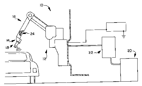
As best illustrated in Fig. 1, a system 10 incorporating
the present invention comprises a coating robot 12, such as
a General Motors-Fanuc Model P-150 robot, at the remote end 14
of the arm 16 of which is mounted a coating dispensing device
18, such as a Model EMF dual-headed, electrostatic, water-
or solvent-base base paint spray gun available from ITW
Automotive Division, 8227 Northwest Boulevard, Suite 230,
21~~~4'~4
_8_
Indianapolis, Indiana 46278. Depending upon the
application and/or the type of dispensing device employed
in a particular coating operation, it may be necessary to
mount the dispensing device 18 on an insulator (not
shown) to isolate it electrically from the robot arm 16.
The dispensing device 18 is selectively coupled to a
source 20 of coating material. If the coating material
is electrically conductive, it may be necessary to couple
the device 18 to the source 20 through a voltage block
22, for example, of the type described in U.S. Patent
5,154,357. A hose assembly manifold plate is provided
between the remote end 24 of the robot arm 16 and the
dispensing device 18 to couple the dispensing device 18
to the lines through which various services are provided
to the dispensing device 18.
A prior art manifold plate 30 is illustrated in Fig.
2. It includes connections for atomizing air 32, fan
shaping air 34,.electrical cable 36, a paint supply line
38, a waste fluid, or dump, line 40, exhaust air 42 and
pilot air signal lines for the paint pressure regulator
44, paint trigger valve 46, and dump valve 48.
Typically, these service lines extend through an
approximately two inch (about 5.1 cm) diameter robot
wrist some two to three inches (about 5.1 to about 7.6
cm) away from the manifold plate. Consequently, all of
these connections are made to the robot arm 16 side or
wrist side of manifold plate 30 within about a two inch
(about 5.1 cm) diameter circle. A hose or line for air
or liquid is attached to each of these connections,
except, of course, for the electrical connection. An
electrical cable is connected there. As will be
appreciated, this close spacing limits the amount of
manipulation of these fittings and the hoses that are
attached to them. Additionally, these connections are
not rotary connections. Movement of the robot arm 16 can
-g-
result in twisting and breakage of the lines. This can
be particularly messy if the paint line 38 or the dump
line 40 is broken. Paint or waste can leak into the
robot arm 16. This ordinarily will result in the robot
12 having to be taken out of service, disassembled,
cleaned, and reassembled prior to being placed back in
service. This can take a day or longer.
Referring now to Figs. -3-4, modified paint supply 60
and dump 62 connections have been incorporated into a
manifold plate 64. Each of the connections 60, 62 is
provided with an outer fluid fitting 66 provided with a
ferrule nut 68 for connecting the paint supply or dump
hose 70 to the fitting 66. An internal male stem 72
extends into the open lumen of the hose 70 to receive or
transfer the liquid paint or waste liquid, respectively,
from or to the hose 70. Fitting 66 extends through
bearings 76, 78 on the wrist 80 and atomizer 82 sides,
respectively, of the manifold plate 64. The illustrated
bearings 76, 78 are ball bearings. While ball bearings
are an excellent choice for this application because they
can be of the sealed and permanently lubricated type,
sealed, penaanently lubricated roller bearings or sleeve
bearings can also be used with satisfactory results.
Sleeve bearings will be characterized by slightly higher
friction because a sleeve bearing will contact the
fitting 66 along a substantially greater portion of its
length. However, since the entire fitting 66 is machined
for relatively free sliding insertion through the
manifold plate 64, even this friction should not be
excessive.
At its atomizer 82 end, each fitting 66 is adapted
to receive an atomizer fluid fitting 84 equipped with an
O-ring 86 to seal the connection against leakage of paint
or waste liquid. Additionally, a face-sealing 0-ring 90
and an O-ring seal 92 are provided to reduce the
2~.404'~~~
-10-
likelihood of leakage between the atomizer 82 and
manifold plate 64, and along the fitting 66 past the
bearing 78.
The outside surface 96 of each fitting 66 is
provided with a circumferential retaining groove 98. A
passageway 100 extends inwardly from the edge 102 of
manifold plate 64 and is threaded along part of its
length. Each passageway 100 threadedly receives a spring
loaded locking pin 104. The distal end 106 of each
locking pin 104 is designed to enter the retaining groove
98 of a respective fitting 66, and remain engaged with
the respective retaining groove 98 until the respective
locking pin 104 is removed, disengaging it and permitting
the respective fitting 66 to be withdrawn from the
manifold plate 64.
Referring now to Fig. 5, another embodiment of the
invention is provided with an outer fluid fitting 166
provided with a ferrule nut 168 for connecting the paint
supply or dump hose 170 to the fitting 166. Fitting 166
receives a thrust washer 176, the retaining flange or
collar 177 of a connector 179, and a thrust washer 178.
The opposite, axially facing surfaces of flange 177 are
flat and smooth to bear slidably against the abutting
faces of washers 176, 178. Relative rotation between
connector 179 and fitting 166 is thus achieved. A snap-
type locking ring 180 snaps into a,groove 181 provided
therefor in fitting 166 to capture fitting 166 and
connector 179 in this relatively rotatable configuration.
Threads 183 on the opposite end 185 of connector 179
engage complementary threads in the paint or waste
opening, respectively, of a manifold plate, not shown, of
the general type illustrated in Figs. 3-4 to.f ix
connector 179 in the manifold plate. The interior of end
185 of connector 179 is configured to receive an atomizer
fluid fitting of the general type illustrated at 84 in
2140474
-11-
Figs. 3-4. An appropriate O-ring seal 187 is provided in
a groove 189 around the interior circumference of fitting
166 to seal against the outer circumference of connector
179 where the outer circumference of connector 179 is
rotatably received within the interior circumference of
fitting 166.
Referring to Fig. 6, another embodiment of the
invention is provided with fluid fittings 266, 366
provided with ferrule nuts 268, 368 for placement in the
paint supply or dump hose 270 adjacent to, but spaced a
short distance from, the manifold plate. This connection
can be located, for example, in the wrist about two
inches (about 5 cm) from the manifold plate. Fitting 266'
receives a thrust washer 276, the retaining flange or
collar 277 of fitting 366, and a thrust washer 278. The
opposite, axially facing surfaces of flange 277 are flat
and smooth to bear slidably against the abutting faces of
washers 276, 278. Relative rotation between fittings
266, 366 is thus achieved. A snap-type locking ring 280
snaps into a groove 281 provided therefor in fitting 266
to capture fittings 266 and 366 in this relatively
rotatable configuration. The connection of hose 270 to
the manifold plate need not be a rotary connection. In
this embodiment, the hose 270 is cut at the location at
which the rotary connection is to be made. This gives
the user the flexibility to decide how far up the robot
arm from the manifold plate to place the rotary
connection.