Note: Descriptions are shown in the official language in which they were submitted.
OS 1 7
This is a divisional application of cop~n~ing
application 2,063,224, filed March 17, 1992.
~A-K(i~uNv OF THE lNVk.
l. Field of the Invention
The present invention relates to low temperature or cold
food storage e~i -nt and, more particularly, to low
tempeL~Lu~e food storage e~ nt with which it i8 pos8ihle ,, ~,~
to keep food in cold storage for a long period of time
.,
th~uy1~ utilization of low temperatures available during the
winter in cold districts and to transport the food while
keeping it cold in the storeroom without the n~cessity of
trAn~hirping it to a refrigerator truck or the like.
2. Description of the Prior Art -~
One method that has heretofore been used to keep food in
lS cold storage is to ut;l;ze low temperatures avA~lAhle during
the winter in cold districts. A simple storage of this kind
i~ a storage pit which 18 dug in the y-~ulld and ut;l; 70S .~ '.' .?} " '.
latent and sensible heat of the ~ul v~ ; ng frozen soil to
~; keep food in cold storage for a long period of time.
~20 There has been ~vpose~ the use of heat pipes for
c~ly forming a frozen soil layer around the storage pit as
disclosed in JApAne~e Patent Laid-Open Publication No. ',.,',',~':';'.,~'f~''i,'',
233957/90, for example. The cold storage e~ described
in this JArAn~ce do¢ument is made up of a water-barrier heat - 'f~
~25 ~n~ Ating layer provided in the yL~u~ld~ a food storeroom
pxovided inside the heat ~n~lAting layer, and heat pipes
' ~ .,. ' '
21~0517
~;:-
having their lower end portions inserted into the ~u.d
between the water-barrier heat insulating layer and the - -
stockroom However, the cold storage e~i - L of this kind
has technical problems described below
With the cold storage e~i -nt set forth in the above-
identified JApAnece document, food is kept at low
temperatures in the underyLound storeroom during the winter,
and hence in the case of shipment it must be carried out of
the storeroom and loaded on a refrigerated truck or the like;
this is very ~i - con~u~ming and laborious work~
Moreover, the frozen 80il layer, which serves as a ~-
cooling or chilling source, is frozen by letting in the cold ~-
or chilly outside air thl~uyh the heat pipes, and hence its
frozen state varies with the outside air tempe.~Lù~e
SUMMARY OF THE l~VL ~lON
The pLas6rL invention provides a low t~ -_aLu.e food
storage e~ L and a tem~e~Lu.e colL-ol which enables
food kept in cold storage to be Lr~oLLed without being
reFh~ rpe~ to other trA~ L Lation means and to be held in
.,, "- ,-
good preservation during the trAnsportation period, for
exampl-, for at least several days
More partic~larly, in one aspect (claimed in the parent ;~
application) the invention provides low temperature food
storage equipment compri~ing an iC~hollce and a food storeroom
each ~u.--~w ded by a heat insulator, a temperature sensor '
~ ose~ in said stol loom, a first heat eYchAnging pipe
:: ,. ~ ,.
' ~'' ' '' ~'' "'"''''''''''''
" ~ '' ,' ,''~
-' ~! 1'4 ~)~; 1 7
extPnA; ng from a lower portion of said icehouse to an upper
portion of said storeroom, a e-~conA heat ~YrhAnging pipe
ext~n~;n~ from an upper portion of said ic~ho~ee to a lower ~-
portion of said storeroom, fans provided in said pipes for
circulating air beL~een said iC~hsl~ce and said stG~eL. , and
means for selecting the air flow directions in said first and
secon~ heat eyr-hAnging pipes on the basis of the temperature
detected by said temperature sensor.
- With the low temperature food storage e~l; -nt of the
above construction, the temperature in the ic~ho~lee i~
substantially free from the influence of a r-h~nge in the
outside air temperature, bec~ee the icehollee is ~ULLO'"'ded
by the ine~lAtor. The heat source for coolin1 the sto~eL. ~ -i
is ice frozen by the outside air, and hence is stabl- in
temperature and humidity. The temperature in the storeroom ,'
wherein per;ehAhle foods are 8tock~A i8 conLlolled to etay
within a pleda-ermined tem~e~aLu~e range on the basis of a
detected value of a tempe.aLuLe s~ne~r. Ilo~eovér, the heat '
-h~ng~ intel~osed beL~3en the ic~ho~-ee and the StGle~ is
det~-r-hAhle, and when it is L. ~ed, the storeroom can be
loaded on a truck or the like, with foods s~ock~A therein. - ;~
. , . ,: .
In the tempe~aLu~e col.L.ol method aspect of the
" j j, ",
invention, the air flow directions in the first and s~cond ~ : :
heat ~Yr-hAnging pipes are selected on the basis of thc
temperature detected by the temperature s~n~or. ~ s
' " .'~"~"''''.'.
_ 3 _
. .. ~ ,'''. ~.
-
0~ 1 7
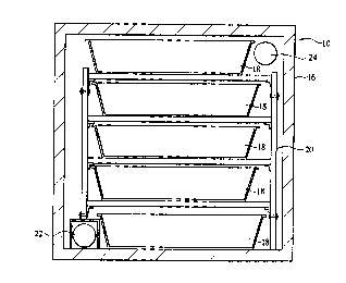
BRIEF DESCRIPTION OF THE DRAWINGS
Fig. 1 i5 a longit~;nAl-sectional view of low
temperature storage equipment according to an embodiment of
the present invention;
Fig. 2 is a cross-sectional view of the low tem~e~LuL~
storage e~~ nt shown in Fig. l;
Figs. 3 and 4 are schematic dia~ - for expl~ining
' ''- ~ - ' '' '
:: :25
- 3a -
', ;.',,'.',,''.',,'',''' ''',.'~ ,
': 21~10~1 ~
an iceho~ e of the storage e~
Fig. S ic a C~h -tic diagram ~or eXp2;~in;n~ a food
toreroo~ of the ctorage es{~ nt;
Fig~ md 6B are sahe~atic di~1~ ~ for ~Y~ ini~
tlle pr~n~ p~6 of heat ~Y~.hJ~ pipes for u~;e in t~e
D~ pment;
Fig. 7 16 a gche~at~¢ diagra~ ~or ~T1A~n;n~ the
~ ent of te~ ~ swi~ches in the food ~i~ of
tl~e.~ e equ~p~ent;
Fig. 8 i1; a table ~or ~yr~ n~ ,ol of
t~.~L~e in the food ~L~, -
Fig. 9 ~; a ~ n~ nAl view ~ g
another embodi~ënt of the ~torage ~i_ nt Of the ~.~.L
i~,_.ILion; and
Fig. 10 ~ its ~0~ ~ ~Al View. -
~ "" ~ L~ S
A ~'.q ~ e given, with ~er~---.~ to the f
~gs, of ~f~.~ e~ts o. f the present in~ n,
Flgs. 1 thr~ugh 8 ~ L~ ~ e~ t o* the l~r
.r~ ~ ~tor~g~ e~iuipm~nt ~Iccording to t~ t,.~~L
n~ Whi.Ch ha~ an ll~h~-6e 10 and a food ~torero~m 26 ~ .
~ eac:h envelaq?~ by a heat ~n~ tor~ The ic~hs~e 10 and the
_LOo~ 26 ~re i .~h.~ a ~4~h:~h-l,~ heat ' -
. 25 12 ~; ,posed, ~ _t. ~_. them.
q~he i~ 10 i~; re~n~
shape and i~ so~ed of an ;C~hov~e ~ 16 having a door 14
~t one end and entirely ~u. ~ e~ by a heat insulator and
--
21~0Sl ~
trays 18 placed therein. As shown in Figs. 3 and 4, the trays
18 are mounted on shelves 20 provided one above another at
predete~ ~ ne~ ~D~~L intervals in the ic~ho~e body 16. The
trays 18 are each inverted LL~l-e7~1~1 in crosC section and
~v~DL~u~ed 80 that it Will not break even when water
cont~ne~ therein freezes.
T.he water to be cont~no~ in such ~ tray 18 i8.water
that has dissolved therein a ~,~o~- mined .a~cunt of E~lt, for
i.~t~.oe. T.he water is coo7~ and E~oz_. into ice by the cold
~ ~C~ air which is admitted into the i¢ehouse body 16 by
oF~n~nq the door 14. Nhen the water in ench tr~y 18 i8 thus
~ frozen into ice, the door 14 i8 rl~ce~
The D~olG~vm 26 for storing per~ hl~ food~ is ~ -
provided adjacent the ~Ak~ 10, ~nd in this embodiment the -~
~5 former has about ~he sa~e shape ~ that of the latter. Fig. S
- is a ~.o~ ~e~ n~l v~ew of the D~ OO~ 26, which i8
DU~ ky a heat insulator and in which foods.(y~ oe_, .. .
for ~xample~ 26a pa¢ked in C~L~LC~ boxes or s~lar
co~t~n~s are rlr~ ~ one above another. -
The heat ~h , ~ 12 cooprises, ~n this e~kodi~ent, .
a rlrst heat exchanging pipe 22 whi¢h extends along the ~ot~om .
o~ the ~a~ e body 16 and Ih~ e to and along the ¢~ ng of
the ~O~eLOOm 26 and a ~ec~ heat ~ ...J;ng pipG 24 which
extend~ along the c~ n~ of the lo~ho~ bcdy 16 and lh-.-,~
to and along the bottom of the ~v,e~oom 26. The heat ..
~ ha~Jlng pipes 22 and 24 nre made of vinyl chloride and each
portion exten~ng in the la~ho-~-e bady 16 and the ~V.~Loom 26
has a number of ~eL~v.~ions. The 8um total of the areas of.
~1~051~
such perforations made in each pipe i8 nearly equal to the
cross-sectional area of the pipe.
The heat eYrhAnging pipes 22 and 24 are de~ArhAhly
c~ e~ed to the ~o~oom 26 ~y means of, for instance,
S col~rl~n~c composed of bolts and nuts and ~t~pose~ bet
L~ L lines 28 of the pipes 22 ~nd 24 and the DLvra~m Z6 in
6uch a ~anner that the pipes 22 ~n~ 24 are part~y left in the
~LG~e~Om 26 when they are d~sco~.G~Le~ fro~ the ~ ~~~ ~ 10.
Of ~v~e, the pipes 22 and 24 are ~lalt~ 80 that they can be
r~ e~ out of the ~u~Loom 26 entlraly.
The ~ir~t ~nd n~ ~-l heat ~ h_~J~ng pipes 22 snd 24
e~ch have its intermedi~te portion f~Gd into two bi~ 'h~ 28
whioh ~oin again. In the ~,A... hr~ 28 there are provided ~ .
~l~ct~omagn~t~c shutters Dl to D4 and fans Fl to F4 as shown
15 in Fig. 6. m e ~c~om~.gn~o Fh~tt~rs Dl to D4 and the :~
f~ns Fl t~ F4 are c~ in seriGs a~ -' ,1gte~ in Fig. 7
~nd thGy ~re c~LLolled ky the~r~6DL~L~ THl to TH4 (see Fig. .l) ~:
disposed at upper an~ lower pos~t$ons in the ~vi~uOOm 26.
Flg. 8 is ~ tabl~ show$ng combinations o~ the
20 sj.~s~cmagnetic sh~LLdL~ Dl to D4 ~nd the fan~ Fl to.F4 whidh . ~.
are driven or ~o~ in accordance with the ~tate of the .
thermcnL~L~ THl to TH4. In this example the thermGDL~L~ Tffl
and TH2 cLl jc' at the upper positions in the D~qlo~m 26
~ .
are set ~o that they turn ON at 4C~ ~nd OFF at'2C~. The
2S thermostats TH3 and TH4 at the lower poDitions.are ~et ~o that. -
they turn OFF at 2C~ and ON at OC~. The elec*roma~n~t~a ~ -
~huLLGl~ Dl, D4 and the fans Fl, F4 are drivèn or C~opFe~ by
the ON-OFF o~eL~ion of the thermostats THl and TH2 ~
.:
, . ;:
~ ' ' . , ' ' . ,. ";,~'.' '' -
. .
:. :: .
21~0S~
at the upper positions, where~s the electromagnetiC shutters
D2, D3 and the fans F2, F3 are driven or stopped ~y the ON-OFF
o~el~ion of the ~h-- - La~s TH3 and TH4 ~i~posed at the lower
positions.
When ~he tem~Lu,e at the upper portion in the
~~0La~dOm 26 i8 h~h~r than 4 C~, the ele~lom~n~ shutter~
Dl, D4 and the fans Fl, F4 arQ driven. -In thi8 ~ ~v~ the ~ :
firgt heat -'-'h''-J~ p~pe 22 takes therein chilly a~r at the
lower portion in the icehouse 10 ~nd ~rpli~fi it to the upper
10 - portion of the storQroo~ 26. ~he ~c~ heat ~Y-'~ JIn~ pipe ; ~'
24 ~ke6 therein air ~t the lower portion in the Dt ~m 26
and ~h~-~E it into the upper portion of the ~c~ 10.
Thus the chilly ~ix in the ~c~~ 10 circulate~ via the
route: lower portion of ~c~h~ 10 - upper portion of ;~
~LG.e oom 26 - lower portion of storeroom 26 ~ upper portion
of ~~k.~ 10 ~ lower portion of tc~ ? 10. . -~
When the te~e~L~ at the lower ~ide in the ~ -
storeroom 26 i8 belvw OC~, the ~lec~rom~ne~c ~h--~L~Jd D2, D3 ~ ~ -
an~ the fans F2, F3 are driven. In this case, the first h~at
~0 ~ Jt~g pipe 22 takes therein the air at the upper portion ~ :
ln tho ~ oom 26 ~nd A~ .h~ it into the low~r portion
o~ the lc~ e 10. The ~ac~ ~ heat ~ ".Jin~ pipe 24 t~kee
therein at the upper portion in the ia~h~ e 10 ohilly air
.with relati~ely higher tem~e~LuL~ than that of the air ~t the
~j .
25 lower portion in the ~oh,----e 10 and ~urrl;~ it to the lower; . ~ :
portion in tha ~L~leL~m 26. ~hus the chilly air in the
~C~ t 10 circNlates vla the route: upper portion of :.
~L~_ ~om 26 ~ lower portion of ~ce~o~e 10 ~ upper portion of
.
7 . ' ~
-' :': '., ~:'':
21~0Sl~ ~
ic~ho~ce 10 - lower portion of stol~c 26 - upper portion of
storeroom 26.
In this way, the tem~el~Lule in the sto~c 26 is
held in the range of ~eL~_e.. O and 4C~ and the humldity is
held at about 95%.
A deccription will be given, with refa~ e to Figs.
9 and 10, of ~ J1h,~ embodi~ent of the ~.~IL ~nvention. In
the low tem4~Lu~e food ~v~ _e equipment of thi8 embodiment
the ~~h~ ce 10 and the ~Lv~e~vm 26 are ~n~t~l~ed
~ lly of eadh other and they are ilte~c~ by the
det~dh~ble heat ~ 'r _ 12 ~I~G~e~ them.
The ~C~ t 10 and the ~Lv.~4vvm 26 are each formed
by a parall~lsr~re~c steel container having a door at the
outer end ~e~eor, whioh can be shut airtightly (not shv-wn3.
The ~c~ e lo and the sto~er~om 26 ~re both entirely
~u.,v~ d~ by heat ~n~lAtors.
In the ~fr~ 0 there are st~cked drums 18a, which
cont-~in water, for i~ta..~e, having ~i~sol~ea therein a
predeter-ln d a~ount o~ ~alt, and the water $8 f~v ~. into ice
wh~n the outside air temk_l~Lu~_ becomes low. In the
storeroom 26 there are ~v~c~ a large amount of food
~v~aLoes, for example) cont~n~ in ~ ~G~Ld boxes or the
like. The drums 18a may also be ~ubstituted with the trays 18
j ~
u~ed in the embodiment described above.
The heat ~ in~ t~es a pair of straight
heat ~ ng pipes 22a and 24a, Uh~v~h which the i~k, -e
10 and the ~v,_,oom 26 illteu~ommunicate, and ~C-driven axial -
~ans 28 and 28a a~'- h~ to the heat ~ n~.Jin~ pipes 22a and
- 8 --
2190Sl ~
24a, respectively. The heat ~Y~hAnging pipes 22a and 24a are
larger in A~ u than those of the axial fans 28 and 28a.
That one of the two heat ~Y~hAngi n~ pipes 22a and 24a which
inLlG~uces chilly air from the i~k, -e lO into the DLv~e
26 i8 prov~ded at the upper side and the other which
~.L,o~ce~ the air from the ~Lv~cu~m 26 into the ~c~ho~e 10
is provided at the lower sidQ. ~-
The heat ~ J~n~ pipes 22a ~nd 24a each have in
its~inter~ediate portion a fl~Y~hle pipe 30 for A~C~ in~
0 the ~c~ e 10 fro~ the D~U~e~ 26 while partly re~aining
itself in the latter, ~ - -l shutter 32 whidh i~ ~lo~e~ in
the case of free~ing the water in the Aru~s 18a in the ~ -
~c~~ - 10, and a blank flange 34 for taking in the o~
air. m e fl~Y~h~ pipes 30, the ~anual shutters 32 and the
blank fl~ng~5 34 are co.~l with heat ~n~ tors 36 ~ ~e~
a~ ~ them.
In the ~ ~ 10 there i~ provided a baL 38 for
dri~ing the axial fans 28 and 28a, the baLL~u~ 38 being
co~.e_t*d to a solar-cell panel ~0 ~.L~ on the top of the
1~ - 10. With the storage equipment o~ the above ~-
w~t~ Q~ the water conta~noA in the drums 18a in the
~o~h ~-? 10 is f~. and the chilly air in the io~h~-e 10 is
circulated as in~cAted by the a,~. as shown in Fig. 9, by
driving the axial fans 28 ana 28a, whereby food stored in the
storeroom 26 is kept in cold ~LG~
,,
Since the heat eYr-h ~ 12 interpo~ed ~et _e~. the
~c~ 10 and the storeroom 26 has the pair of straight heat
~han~ng pipes 22a and 24a and the DC-driven axial fans 28
~1~051'~
and 28a attached to the heat ~h~n~ n~ pipes 22a and 24a
respectively, and since the heat ~h~nging pipes 22a and 24a
are larger in diameter than those of the axial fans 28 and
28a, it is po~sihle to reduce p-e~ule lo~sss of the heat
~ J;ng pipes 22a and 24a m~ko~ly and to da~aa~e the ~low
velocity in the pipes while ce~ing a~ v~liate air flow rate-
~herein, thus the DC-driven axial f~ns 28 and 28a of low
~e~y~ 1088 are employable.
According to this embodiment, the use of the battery
38 and-the solar-cell panel 40 for driving the axial fans 28
~nd 28a m~kes it poF~h7e to keep food in cold D~V~, for
long F~rlo~ of time without the ~e~-~~ity of ~upplying ~,e~y~
from the outside by e-~e~y~ supply means such as a power supply
lead. Tn~ ntally, since the power consumption of the axial
fans 28 and 28a i~ a v~d 10 watts, they can al80 be driven ~y
wind power generation ~n place of the solar-cell panel 40.
A~ many ~a~.L~y and widely di$ferent embodiments ~ -
of thi~ invention may be m~de without departing fr-m the
spirit and scope LL_,e~L, it is to ~e ~ Lwd that the
~nVDnt~n i~ not li~ted to the ~ec-;ffc ~mbcdi-cnts LL evr
&'-~ a8 ~f~n~ in the ~ ~ claims.
- ::
.. , :
. .
-
. . . ~,,, :-:
. . ,~ -:~; .
- - . . ~.
~: "