Note: Descriptions are shown in the official language in which they were submitted.
2140~05
2339-21-00
1485.042
END BASE ASSEHBLY FOR VE~ICLE AIRBAG HODULE
RELATED APPLICATION
This application is a continuation-in-part of U.S.
Application Ser. No. 08/213,176 filed March 14, 1994 by D.R.
Lauritzen, D.J. Green, and L.D. Rose for COMBINED REACTION CAN
AND INFLATOR WITH EXTRUDED GENERANT and assigned to the same
assignee as the present invention.
TECHNICAL FIELD
This invention relates to the field of automotive
airbag modules. More particularly, it relates to an improved
filter pack and base construction for passenger side airbag
modules.
BACR~Ku~Nv ART
The passenger side airbag module assembly for a motor
vehicle normally includes a trough-shaped reaction canister which
holds the folded airbag and is installed behind the dash board.
An inflator housing is associated with the reaction canister and
encloses a gas generant normally contained, in turn, within a
cylindrical filter pack. The filter pack is a steel mesh
material retained within the inflator housing by a base or bases.
These bases are normally installed by welding, or swaging the
2140~05
-- 2
inflator housing around their ends. Upon the occurence of a
collision of sufficient magnitude, the generator is ignited and
gases from the burning charge pass through openings in the
inflator housing to inflate the airbag.
Airbag modules constructed in accordance with the prior
art have certain deficiencies which it would be desirable to
overcome. Many of these deficiencies relate to the end bases
which close the inflator housing. Conventionally, these bases
require a seal between the base and the filter pack and diameters
that fit tight in the inflator housing for centering. These
filter packs in turn require a sizing operation to control their
diameter tolerance for installation in the inflator housing.
Another problem arises where seals between the bases
and filter pack are used. There is a tendency for the seal to
off-gas causing flaming subsequent to airbag actuation.
A further problem arises from the need for an auto
ignition charge within the inflator. The purpose of this charge
is to set off the main gas generant causing the inflator to
function early, in the event of a warehouse or vehicle fire, at
a temperature where the inflator housing and reaction canister
still retain their structural integrity. This requires good heat
transfer to the auto ignition charge and good access of the
ignited auto ignition charge to the inflator igniter. To that
effect, it would be desirable to improve the heat transfer
characteristics from the outer wall to the auto ignition charge.
21407~5
- 3 -
Accordingly, it is a primary object of the present
invention to provide an end base construction which is not
orientation critical. Another object is to provide such a
construction wherein sealing is improved without the need for 0-
rings. Another object is to provide such a construction wherein
the ends of the filter pack are removed from the gas path.
Another object is to provide such a construction wherein the heat
transmission characteristics from the outer wall of the inflator
housing to the internally housed auto ignition charge is
improved. Other objects, features and advantages will become
apparent from the following description and appended claims.
DISCLOSURE OF INVENTION
The present invention includes a substantially
cylindrical inflator housing having a ported sidewall for venting
inflating gas to an airbag. A gas generant assembly is posi-
tioned within the housing and includes a substantially cylindri-
cal filter which encloses a gas generant. A first cup-shaped end
base has a circular main body which closes the end of the
inflator housing, a cylindrical outer wall which surrounds one
end of the filter within the inflator housing sidewall, and a
cylindrical inner wall which extends from the main body parallel
to the outer wall. A preload member is positioned between the
inner wall of the base and the gas generant.
A second end base closes the opposite end of the
inflator housing. It is very similar to the first end base, but
21~0705
-- 4
also includes means for retaining an initiator. Both end bases
are free of any positive restraints of rotational movement about
the longitudinal axis of the cylindrical filter. Means are
provided for compressing a sheet gasket against each of the end
bases to seal the ends of the inflator housing.
BRIEF DESCRIPTION OF ln~ DRAWINGS
FIG. 1 is an elevational view in partial cross-section
of an igniter end base in accordance with the present invention;
FIG. 2 is an elevational view, also in partial cross-
section, of an inflator housing enclosing a filter pack assembly
in accordance with the present invention; and
FIG. 3 is an exploded isometric view illustrating the
assembly of an inflator in accordance with the present invention.
BEST MODE FOR CAKKYlNG OUT THE INVENTION
FIG. 1 illustrates an initiator end base 10 in
accordance with the present invention. It is made from a
material of good heat conductivity such as, for example,
aluminum. It is basically cup-shaped and includes a circular
main body 12 surrounded by a wall 14 which has the form of an
annular wedge and tapers to a narrow rim 16. Extending from the
body 12 and concentric with outer wall 14 is a shorter inner wall
18 which tapers to a relatively thicker rim 20. A cylindrical
boss 22 protrudes from the opposite side of the body 12 and
defines a multi-diametered cylindrical opening 24 terminating in
6~1407~5
-- 5 --
a conical seat 26 surrounded by a relatively thin cylindrical
retainer 28.
The various features of the invention will be best
understood and appreciated by reference to FIGS. 2 and 3. FIG.
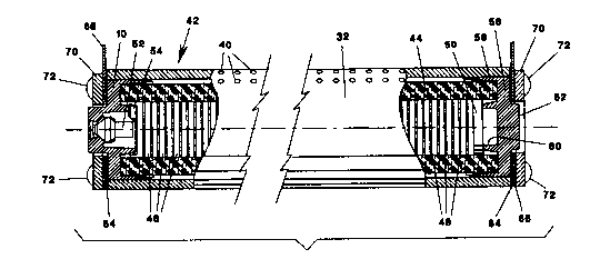
3 illustrates a combined reaction canister 30 and ignition
chamber 32. The reaction canister 30 includes sidewalls 34, 36
which form a trough for containing a folded airbag. The canister
and ignition chamber may be extruded from, for example, aluminum,
and may include such features as screw retention channels 38,
only two of which are illustrated. One wall of the ignition
chamber 32 also forms the floor of the reaction canister 30 and
is provided with openings 40 (FIG. 2) which emit inflating gas
into the airbag.
The inflating gas is generated from a filter pack 42.
Filter pack 42 comprises a cylindrical mesh screen 44 which
contains the gas generant. The generant may take any of a number
of forms. The one illustrated comprises a stack of pyrotechnic
washer-like disks 46 separated by screen washers 48 which provide
gas paths to the openings 40. One end of the filter pack 42
includes a preload 50. The preload 50 may be of any desired type
such as a silicone wafer used in the prior art or, preferably,
it may be of the type disclosed in co-pending U.S. Application
Serial No. 08/212258 filed April 14, 1994 by D.R. Lauritzen and
J.L. Ralston titled Generant Preload and Tolerance Takeup
Assembly and assigned to the same assignee as the present
invention. The disclosure of that application is incorporated
herein by reference.
- Z1407~5
A conventional initiator 52 is mounted in the conical
seat 26 of the initiator end base 10 and the retainer 28 is
crimped upon it as illustrated in FIG. 2 to hold it in place.
The cavity between the outer wall 14 and the inner wall 18
receives the auto ignition charge which is held in place by a
cup-shaped screen 54. The assembled initiator end base 10 is
press fitted onto the end of the filter pack 42. The tapered
outer wall 14 centers and compresses the end of the mesh screen
44 and the rim 20 of inner wall 18 presses against the generant
charge. Because the filter pack 42 and the initiator end base
10 are both circular and symmetrical, their rotational relation-
ship is unimportant.
The opposite end of the filter pack 42 is closed by an
end base 56. As will be seen in FIG. 2, the end base 56 is very
similar to the initiator end base 10 but does not include means
for retaining an initiator. It does, however, include a similar
outer wall 58 and inner wall 60 and a raised boss 62 on its outer
surface. The end base 56 is mounted on the end of the filter
pack 42 in a similar fashion as the initiator end base 10 and
similarly centers and compresses the mesh screen 44. It will
also be noted that the inner wall 60 bears against and compresses
the preload 50 to maintain the pyrotechnic disks 46 under
compression.
The filter pack 42 assembly including the end bases 10
and 56 is inserted within the ignition chamber 32 and a flat
gasket 64 is applied to each end. An end plate 66 is secured to
each end of the reaction canister 30 by means of screws 68,
21~U7~5
_ -- 7
thereby completing the trough of the reaction canister. Finally,
retaining plates 70 are mounted to the assembly by means of
screws 72 which extend into screw retention channels (not
illustrated) formed in the reaction canister.
It will now be apparent that the construction described
above has fully met all the objectives of this invention. The
round bases can be easily manufactured with only minor machining
required and they require no orientation relative to the filter
pack. They may be press fitted onto the ends of the filter pack,
and the outer walls become end seals which keep the ends of the
filter pack out of the gas path. The flat faces on the end bases
permit use of a flat gasket rather than an O-ring, which improves
the sealing. Furthermore, there is a substantial area of
engagement between the outer wall 14 of the initiator end base
10 with the inner surface of the wall of the ignition chamber 32.
As a result, the heat transfer path from the outer wall of the
canister 30 to the auto ignition charge is greatly enhanced.
It is believed that the many advantages of this
invention will now be apparent to those skilled in the art. It
will also be apparent that a number of variations and modifica-
tions may be made therein without departing from its spirit and
scope. Accordingly, the foregoing description is to be construed
as illustrative only, rather than limiting. This invention is
limited only by the scope of the following claims.