Note: Descriptions are shown in the official language in which they were submitted.
CA 02141339 1998-03-24
Adjustable Girth Former
Back~round of the Invention
This invention relates to machines for packaging
rolls or groups of rolls in a film, and in particular to
an adjustable girth control for a tube former in such
machines.
In modern packaging machinery, rolled products, such
as rolls of toilet tissue or paper towels, are conveyed
individually or in groups, encapsulated in a plastic film
formed into a tube, and the tube is then severed between
succeeding products and sealed into individual packages.
A basic packaging machine is illustrated and described in
US Patent No. 4,430,844.
In such machines, a girth former is included for
forming plastic film into a tube extending about the
products to be wrapped. The girth former is sized
specifically to take into account the diameter and
softness of the product being wrapped. Depending on
softness or hardness of the product, diameter variations
can occur, but those variations are limited by the sizing
of the girth former. Therefore, diameter variations can
cause serious production problems, particularly with
harder-wrapped rolls which cannot compress sufficiently.
The result is that such rolls may be too loosely wrapped
with the plastic film, or the rolls may actually jam in
the girth former, causing the machine to be shut down
while the jam is cleared.
In the typical packaging machine such as depicted in
US Patent No. 4,430,844, product is introduced into the
area of the girth former and is conveyed into place,
WO 94/10Q37
~ 1 ~ 1 3 ~3 9 P~r/usg3/l073~ ~
i !
often being somewhat compressed by an upstream preformer sec~ion
before entering the girth former. Often, thP compressio~ set in
the preformer compresses the rolls som~what more tha~ necessary
to ~nter the girth former to insure that the rolls properly enter
th~ former without interference or jamming. As the rolls enter
the girth former, they are encapsulated in a tube of film, and
are also contacted by pull belts which move in unison with the
product and the tube, ensuring a smooth transfer for downstream
sealing.
~ hen~ver a different product is to be pac~ag~d by the
machine, the gir~h former must be changed. That change also
requires adjust~ent of the preformer and realignment of the pull
belts to ensure that product travels smoothly through the girth
~orming area.
The amount of film wrapped about the product tra~eling
throu~h the machine is dictated by the in~ernal dimension of the
girth ~o~mer, and not by the size of the pr~duct itself.
Therefore, if the product is smaller in diameter than intended,
a loose wrap will result, which is undesirable. To overcome this
problem, and to accommodate varying diameters of product
traveling through the machine, an adjustable girth former is
ne~dad.
.
~u~arq of th~ ~n~ention
:~The invention pertains to an adjustable girth control ~or
: ~ tube former in a packa~ing apparatus in which products
comprising individual rolls or groups of roll~ are conveyed
serially and are packaged in a film. The tube former is situated
. .
~ WO 94/10037
r ~ 1 4 ~ 3 3 ~ PC~JUS93/10731
to continuously form a sheet of film into a tube which
encapsulates succeeding product, and the adjustable ~irth control
includes a f orming bod y in the t~be former, the f orming body
being shaped to envelope product passing therethrough. The
forming body has opposite adjustable forming elements and has a
variable gap between the forming elements to accommodate the
adjustment of the elements. Means is :provided, secured to the
forming elements, for shifting the ~orming elements to vary the
internai dimensions of the formlng body.
,: In accordance with the preferred form of the invention, each
~. ~
~ orming eIement comprises a section of the forming body, and the
,
shifting means~includes :means for both: horizontally displaciny
the twa sectlons:a~d vertically displaclng the two sections. The
horizontal displacing means comprises a slide assembly having a
:;slide element secured.to each~f~rming:body's section. It also
includes~means for drawing :the slide e~ements toward and away
from one another to vary the ~ap.;~
:In this form of the invention, the means for drawing the
:slide elements toward~ and away from on~ another comprises a
threade~ bore in each slide element:. The bores are formed in
alignment~:with one another and~th~ ~hreading in one bore is
: forme,d opposite to:the threading ln the other bore. A threaded
rod is engaged in the bores, with the rod having threading
complementary to ~he threading in the borPs.
Means is provided for rotating the rod to draw the ~ections
:toward and away from one~another. ~In the preferred form of ~he
invention, the rotating mea~s comprises a rotary actuator, and
the invention further include~ means for automatically activa~ing
:
WO g4~0037 ~ 3 9 P~T/US~3/~0731
the actuator to rotate ~he rod. That automatic activating means
comprises a processor, with the processor being connected to, and
receiving signals from, an upstream sensor which is positioned
to sense dimensions of product entering the forming body.
For vertically displacing the s ctions of the forming body,
it is preferred that camming means be employed for raising an~
lowering the slide~elements as the gap is varied. In accordance
with one form o~ the invention, the camming means comprises a
pair of spaced, inclined ams, and includes a cam follower in
$ach cam. Each cam fol}ower is secured to an arm, with one arm
being af~ixed to one slide element and the other arm being
af~ixed to the other slide element.
In the preferred form of the invention, a prefo~mer is
located at and in alignment with~an upstream end of the forming
body. The pre~ormer:include~:a pair o~ side forming members, and
means is provided~attached to the si~e forminy members for
adjusting the side forming members toward and away from one
another. It i~ preferred that the rotary actuator be used ~or
simul~aneo~sly ad ju ting the side forming members and the two
:
sections of thQ formir.g body~
Since the two sections of the forming body move relatiYe to
the remaining portion of the forming body, each of the sections
is formed extending from a flex location in the foxminq body.
In accordance with the disclosed:fo~m of the invention, the flex
location comprises a sl~t formed partially across the forming
body.
Th~ gap betwe n ~he two sections of the ~or~ing body
dictate. the amou~t of decrease of the intern~l size of the
~ W~ 94/10~37 ~ PCT/~S93/10731
., !
~'orming bodyO It is preferred that the gap be formed in the
forming body at an ob1ique angle to the direction of travel of
product through the forming body.
:
: Brie~ D~cription of the Drawin~
: ~he invention lS descrlbed in greater detail in the
following description of examples embodying the best mode of the
invention, taken ~in conjunction with:the drawing figures, in
which~
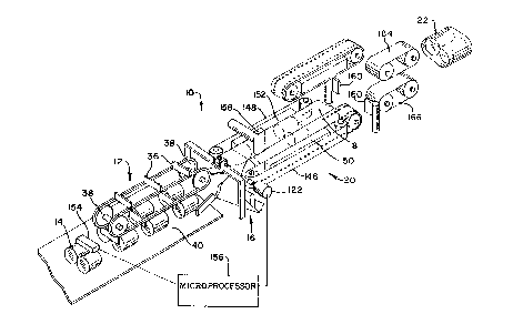
Figu~e l is a perspective view of the girth forming area of
a packaging machine in accordance with the invention, with
: operative portions being eliminated to better show detail,
:~ ~ Fiqure 2 is a top~plan view o~ a girth former of the prior
art design, s~ h~ as that o~ incorporated U.S. Patent No.
; 4~,430,~4A; ~ :
Figure 3 is a top pl~an ~view, si~ilar to Figure 2, but
showing in some detail the adjustabl~e girth fsrmer of the present
nvention; :~
Figure 4 is a~somewhat enlarged view of the girth former
shown in~Figure 3,~illustrating;additional d~tail, but with the
:in~et overhead c~nveyor~removed and with all product eliminated;
igur~ 5 is a side elevational view taken along lines B-B
: of~Figure:4, with the forming skirt or shoulder eliminated;
Figure 6 is an elevational view taken along lines A-A of
Figure 3, and~s~mewh~t enlarged; ::~ :~
Pigure 7 is~a view similar to that of Figure 6, but further
enlarged and o~ a mcdifie~ form o~ th~ invention;
Figure 8 is a schematic' illustration o~ th~ invention,
::
WO 94/10037 ~ 3 3 g P~T/~Sg3/10731 ~
6 :-
looking downstream through ~he girth former, wi~h a middle ..
adjustment of the gap formed in the adjustable forming ~ody;
Figure 9 is a perspective view of Figure 8, with the product
rolls removed; ,
Figur~ 10 is a schema~ic view similar to Figure 8, but
~howing a reduced size of the forming body to accommodate rolls
of smaller diameters;
Figure 11 is a perspective view similar to Figure 10, but
with the product rolls removed and showing the resultant smaller
gap in the forming body;
Figure 12 is also a schematic view similar to Figure 8, but
with the forming body expanded to accommodate rolls of a larger
diamèter; and
:.
Figure 13 i~ a perspective of the adjustment of the
apparatus shown in Figure 12, but with the produ~t rolls removed ~:~
.
: ~ to illustrate detall and showing the re~ulting larger g~p.
'
D~5~Gr~t~5311 of Ex~pla3 E~bo~Yi~
~h~ Be~t ~ode o~ th~ I~v~tio~ -
A girth forming apparatus and the surrounding operative
, .
elQm~nts o~ a packaging machine according to the invention is
depicted generally at 10 in Figure 1. The depic~ed portions of -~
~,~ the~packaging~a;ppa~ra~us include an overhead conveyor section 12
~ for conveying rolls 14 in alignment and regularly into an
: ~ adjus~able girth forming apparatus 16, in whlch th~ rolls are
' '
~ :~ encapsulated in a plastic ~ilm 1~. The film and rolls exit tAe
. .
gir~h ~o~ming apparatus 16 in a pull belt section 20. Succes.cive
rolls or groups of rolls are then severed while encapsulated in .:
2 tubular section of the plastic film to form a partially sea}ed
~ '
W0 94/10037 ~ 1 ~i 339 PCT/U593/10731
package 22. Downs~ream processing seals the ends o~ the package
22 to complete the packaging process in a conventional fashion.
Figure 2 illustrates a prior ar~ form of the invention, such
as that illustrated in Pa~ent No. 4,430,844. Illustrated is an
: overhead conveying apparatus-24 leading into a preformer 26 at
: the mouth of a non-adjustable qirth forming apparatus 28. In a
: con~entional fashion, plastic film is guided by a fixed skirt or
:: :
shoulder 30 in~o the ~orming apparatus 28, which forms the film
into a tube encapsulating~the product 14. Pull belts 31 and 32
of a pull belt section 34 convey th2 encapsulated product
downstream. Figures 3 through 6 illustrate one form of the
improved girth forming apparatus according to the invention.
Figure 7 illustrates a modification. For the purposes of
illustration,~ not alI detail is shown in Figures 3 and 4.
The overhead conveying section 12 may be conventional,
comprising a series o~ paddles 36 endlessly revolved about
sp~ockets 38. The paddles align:and convey the rolls 14 across
a:deadplate 40 into the adjus~able girth forming apparatus 16.
At the exit end of ~e co~veying section 12 and at the
entrance to~ the~ girth forming apparatus 1~, an adjustable
preformer ~42 accepts ~he rolls~14, ~and compresse~ the rolls
su~ciently" to pjermit easy entry into the~ girt~ foFming~
apparatus-16. The preformer 42 and g1rth forming.apparatus 16
are mutually adjustable,~as described in greater detail below,
The girth forming apparatus 16~is composed of two primary
componPnts~ an outer, fixed shoulder 44 and an inner, adjusta~le
forming body 46. The forming body 46 is shaped to 2nvelope the
rolls 14 traveling therethrough, and is composed o~ opposite
W O 94/10037 ~ 33D P~r/US93/1073]
adjustable forming elements or sections 48 and 50 (bes~ shown in
Figures 8 through 13), separated by a variable gap 52 extending
at on oblique angle to the direction of travel through the
forming body 46. A bottom portion 54 of the forming body is
fixed, extending between flex boundaries 56 and 58 defining the
locations where the resp~ctive forming sections 48 and 50 begin.
The flex boundaries 56 and 58 preferably comprise longitudinal
slits in the material of the forming body 46.
~ The forming sections 48 and 50 are adjustable toward and
away from one anoth~r to accommodat2 varying sizes of rolls 14.
As will become evident, the forming sections must be adjusted
: both horizontally and vertically, those adjustments being best
; depicted in Figures 8, 10 and 12.
The adjustment meohanism of the forming sections 48 and 50
in the version o~ the invention illustrated in Figur~ 3 through
6 comprises a slide assembly having a first slide element 60
atkac.hed to the forming section 48 and a sPcond slide element 62
.
:::: a~tached to the forming ~ection 50, Each of the slide elements
:~ inclu~es respecti:ve blocks 64 and 66 at the tops tAereof. Each
of th~ blocks 64 and 65 has an internal threaded bore, the bores
:~ being in alignment and engaging a threaded rod 6~. The threading
:of th~ bores are opposite to one anoth~r, and th~ rod is threaded
in a complem2ntary fashion, so that rstati~n of the rod 68 in one
~ ~ ~ direction will draw the two ~locks 64 and 66 toward one another
;~ (and ~hus the forming sectlons ~ and 50 tcward one another),
while rota~ion of the rod 68 in ~he opposite direction spreads
the blocks 64 and 66 (thus spreading the forming sections ~8 and
50).
~ WO 94/1003? PCT/US93/10731
.
;In addition to horizontal adjustment, the slide elements 60
and 62 are vertically adjustable. The blocks 64 and 66 engage
: an upper trac~ 70. The track 70 is attached to a flat plate 72.
~ A fixed:frame 74 extends above the girth forming apparatus 16,
and includes horizontal arms 76 and 78 carrying between them a
roll 80. The roll 80 is~rotatably mounted between the arms 76
and 78, and is rotatable~by an actuator assembly 82. The roll
80 is also secured to upstanding br2ckets~84 and 86 secured to
the plate 72. There:fore,~by ~ud~icious revolution of the roll 80,
the plate 72 lS raiséd or lowered, raising or lowering the bloc~s
64~ and 66, and tAus the sllde e:lements 60;and 62, raising or
lowering~:;the~respective~forminq sections 48 and 50.
~ A:~modified~fDrm~ of~the girth: forming apparatus of the
?(~i:n~enti~on~:is:~shown ~in ~Figure~?.~ Similar ~elements of the
in~ention~ retain~ the same re~erence~numPra~ls:,: and the outer
formlng~:shoulder~4:4~has~::been~elimlnated ~or purposes of~clarity
and illustràtion. :The girth~forml:ng~apparatus~l6 of~:Figure 7 is
formed~to;~automatical~ly~and~simuItaneous~ly~:shift~ the forming~
sec~ions~ 48~ ~and: ~5:0~ both~horizontally and ~vertically~. The
espe~ti~e~se~tio~ns~48 ànd 50 are~secured~to slide elements 8~
and 9~0'which are topped~by block~s~:92~and 94. In the same fashion
as:~thel~fi~rst form~o~the invention, the bl:ocks 92 and 94 jare
;;: internally: threaded~:in~opposite:;directionsj and are~ engaged by
the~rod'~68,~which is~sim~ilarly~threaded. The blocks 92 and 94
have:upper~portions~engaged on a~track:~6 secured in;a framework
98~ ~which has~ downwardly depending legs 100 and~ 1~2 forming
rotati~onal guides f~or the rod 6:8.
Arms 104: and lO6 are bolted to the b1ocks 92 and 94, and
W~ 9~10~37 s~
PCTJUS93/10731
extend upwardly to respectlve cam followers 108 and 110 located
within respective inclined cam trac~s 112 and 114 in a cam 116.
As the rod 68 is rotated to adjust the blocks 92 and 94
horizontally, the fixed arms 104 and 106 cause their cam
Pollowers 108 and 110 to traverse the inclined cam tracks 112 and
114~. This raises or lowers the entire framework 98, thus raising
or lowering khe forming sec~lons 4~ and 50 at the same time as
the sections are horizontally di~placed. The inclinations of the
~ cam tracks 112 and 114 determine the amount of vertical
adjustmen~ of the forming sections 48 and 50.
; In ei~her form of the inventlon, the rod 68 is secured
through a quick disconnect ~118 to a further rod section 120
xtendlng from a~rotary actuator 122. The actuator 122 is
there~ore utilized to rotate the rod 68 via the disconnect 118
and rod section 120 to alter the positions of the forming
sections 48:~:and 50,~and therefore~alter the in~ernal dimensions
of the~forming body 46.
The~prefo ~ er 42 as~best shown in Figure 4 includes a pair
of ~slde:~formlng ~nhers 124 and 128 which are laterally
: ad3ustable. A bra~ket assembly 130 is attached ~o an outer side
,~: :
o~ the fo~ming membe~ 124,~and a s~milar bracket assembly 132 is
attaGhed~ to an outer~ side of~ the forming ~mh~r 128. ! The~
espective brack~t assemblies 130 and 132 carry rods 134 and $36
which extend to respective~braces 138 and 1~0. The braces 13B
and 140 are, in turn, threadedly: ~ngaged on a rotatable rod 142 .
The rod 142 extends to: a belt 144 which~ as illustrated in
~: :
~ : Figure5 3 and 4, passes about the rod section 120. Thus, when
:~ ~ the rotary actuator 122 is aotivated, ro~ation cf the rod 120
WO 94/1~037
. P~T/VS93/1~73l
~ ~ 4 ~ 3 3 ~
:'
11 .
also rotates the rod 142, drawing the braces 138 and 140 and
attached bracket assemblies 130 and 132 toward and away from one
another, thus adjusting the side forming members 124 and 128 in
the same fashion. Preferably, the belt 144 is in the form of a
chain extending about sprockets mounted on the rods 120 and 142.
The pull belt section 20 comprises a pair of pull belts 1~6
~ :.
and 148~ The pull belts i46:and 148 extend into longitudinal -~
cuts ln the forming body 46, and are laterally adjustable ~means
not illustrated) to accommodate varying sizes of roll~ passing
: therebetween. As shown in Figure l, the pull belts have spaced :
: :holes in them, and vacuum apparatus 150 and 152 is utilized in
a conventional fashion~when nece~sary to aid in conveying of
,. . .
encapsulated rolls~
The~ro~ary actuator :122 can be manually activated, or can
be~automatlcally activated depending on the sizes;of upstream ~
rolls 14 entering the girth~forming apparatus 16. To this end, :--
: a~ sensor~154 (Figure l)~ is located to sense the dimensions of -.
r~lls ~ 14. The sensed dimenslons are transmi~ted ~o a
~ ~ '
microprocessor :156 c~onnected~to operate the actustor 122. The
microprocessor 156~an be programmed in a conventional fashion
: in many manners to actuate ~he rGtary actuator 122 d~pendent upon :;
the~'sizés of the rolls sensed by~the sensor 154. ~For example
tho~microprocessor l56 can compute a running average of the size~
of::the rolls 14, and :based~upon that running a~erage, activate ~'
the~ ac~uator~l22 to incrQase or d~crease the internal di~ension .:~.
:: :of;the~Pormin~ body 46. Other means of sensing and activation --~
o~ the rotary actuator 122 can also b~ used.
In operationt in the illustrated form Qf the invention pair
W09~10~37
, PCl'rU~i93llO731
3 3 9
12
o~ rolls 14 are introduced by the overhead conveying apparatus
12 to the preformer 42. The rolls 14 are sllghtly compressed in
the preformer 42, and are then intro~uced into the forming body
46. At the same time, the film 18 emanates from a source in a
conventional fashion ~not illustrated), extending about and being
~ormed by the shoulder:44, and also en~ering the forming body 46,
encapsula~ing the rolls 14 therebetween. A heat sealer 158 seals
the overlapping film into~a tube. The pull belt section 20 pulls
: _ ~
the rolls and ~ilm through the forming apparatus 16, sending the
now-sealed tub~ :be~ween a pair of rotary paddles 160.
Preferably! the film 18 is pre-perforated as at 162 (Figures 2
and 3j, and the paddles 160 are synGhronously operated to contact
the tube at the perforations 162. Downstream pull belts 164 and
166, operating at~a slightly greater surface velocity than that
o~ th~e pull be~lts 146 and 148, work in conjunction with the
rotary paddles 160 to severe succeeding partial packages ~2 from
the oncomlng tube. The partial package 22 is then end sealed
downstream (means no~ illustrated) in a conventional fashion.
The invention solves a vexing problem of the prior art, and
that is accommodation ~f~arylng sizes of the rolls 14 as the
app~ratus 10 i~ operated. D~pending on the size of the gap 52,
the'~drming sections 48;and 50 can be adj~5ted over a relatively
large ran~e t~ accommodate varying roll sizes.
While a pref~rred form o~ the invention has baen shown in
the drawings and~described~above it will be evident that the
invention can as~ume different ~orms. Various widths and lengths
of packages can be accomodated, not iust individual packages of
two rolls as shown. ~arious changes can be made to the invention
:
:3
,
, .... ..... . ... . ... .... .. . . . . .. . . . . .. . .
:
WO 94/10037 ~ ~ 33~ PCr/US93/10731
1 3
wlthout ;departing from the spirit thereof or scope of the
following claims.
. . .
-.
'::
~: ,