Language selection

Search

Patent 2141340 Summary

Third-party information liability

Some of the information on this Web page has been provided by external sources. The Government of Canada is not responsible for the accuracy, reliability or currency of the information supplied by external sources. Users wishing to rely upon this information should consult directly with the source of the information. Content provided by external sources is not subject to official languages, privacy and accessibility requirements.

Claims and Abstract availability

Any discrepancies in the text and image of the Claims and Abstract are due to differing posting times. Text of the Claims and Abstract are posted:

  • At the time the application is open to public inspection;
  • At the time of issue of the patent (grant).
(12) Patent: (11) CA 2141340
(54) English Title: PYROLYTIC BORON NITRIDE HEATING UNIT
(54) French Title: UNITE DE CHAUFFAGE DE NITRURE DE BORE PAR PYROLYSE
Status: Expired and beyond the Period of Reversal
Bibliographic Data
(51) International Patent Classification (IPC):
  • H05B 03/14 (2006.01)
  • H05B 03/06 (2006.01)
  • H05B 03/08 (2006.01)
(72) Inventors :
  • GILBERT, MICHAEL HENRY SR. (United States of America)
  • HEJL, TIMOTHY JAMES (United States of America)
(73) Owners :
  • ADVANCED CERAMICS CORPORATION
(71) Applicants :
  • ADVANCED CERAMICS CORPORATION (United States of America)
(74) Agent: SMART & BIGGAR LP
(74) Associate agent:
(45) Issued: 1999-01-12
(86) PCT Filing Date: 1993-09-24
(87) Open to Public Inspection: 1994-04-14
Examination requested: 1995-09-27
Availability of licence: N/A
Dedicated to the Public: N/A
(25) Language of filing: English

Patent Cooperation Treaty (PCT): Yes
(86) PCT Filing Number: PCT/US1993/009053
(87) International Publication Number: US1993009053
(85) National Entry: 1995-01-27

(30) Application Priority Data:
Application No. Country/Territory Date
953,156 (United States of America) 1992-09-29

Abstracts

English Abstract


The present invention relates to a pyrolytic boron nitride heating unit composed of a dielectric base of boron nitride and a
pyrolytic graphite heating element having contact ends for connection to an external power supply through a contact assembly
comprising graphite posts connected to the contact ends with each post having a pyrolytic boron nitride coating and exposed
attachment ends spaced a predetermined minimum distance from the contact ends for connection to the power supply. The contact
assembly preferably also includes flexible graphite washers for connection between the contact ends and the graphite posts.


French Abstract

La présente invention consiste en une unité chauffante qui emploie de la nitrure de bore pyrolytique, et un élément de chauffe pyrolytique en graphite muni de bouts de contact destinés à être connectés à une source d'alimentation électrique par un assemblage de contact comprenant des bornes de graphite connectées aux bouts de contact et où chaque borne comporte un revêtement de nitrure de bore pyrolytique et des extrémités de connections exposées espacées à une distance minimale prédéterminée des bouts de contact, pour connection à la source d'alimentation. L'assemblage de contact comprendra idéalement des rondelles flexibles en graphite pour connection entre les bouts de contact et les bornes en graphite.

Claims

Note: Claims are shown in the official language in which they were submitted.

- 6 -
What we claim is:
1. A pyrolytic boron nitride heating unit for use
in a high temperature reactive atmosphere comprising a
dielectric base (10) of boron nitride, a heating element
(14) of pyrolytic graphite (12) superimposed upon said
base (10) and arranged in a serpentine pattern (16) with
said heating element (14) having a pair of contact ends
(17) for providing a series electrical path through said
pyrolytic graphite (12) between the contact ends (17)
thereof and a contact assembly (21) for connecting said
contact ends (17) to an external power supply, said
contact assembly being characterized by a graphite post
(22, 23) for each contact end (17) of said heating element
(14) with one end (26, 27) of each graphite post (24, 25)
attached to a corresponding contact end (17) of said
heating element and having an opposite end (35) spaced a
predetermined distance from said one end for attachment to
said external power supply and a pyrolytic boron nitride
coating encapsulating said heating element (14) and
covering each graphite post (24, 25) so as to form an
integral pyrolytic boron nitride covering except at the
ends (35) of said graphite posts (24, 25) for attachment
to said external power supply.
2. A pyrolytic boron nitride heating unit as
defined in claim 1 wherein each contact end (17) of said
heating element (14) has an opening (19) for attachment
to said graphite post.
3. A pyrolytic boron nitride heating unit as
defined in claim 2 further comprising flexible graphite
washers (30, 31) for use between each contact end of said
heating element and each graphite post.

-7-
4. A pyrolytic boron nitride heating unit as
defined in claim 3 wherein said contact assembly further
comprises a graphite screw (26, 27) for each graphite post
with each graphite post (22, 23) having a corresponding
threaded opening to receive the graphite screw.
5. A pyrolytic boron nitride heating unit as
defined in claim 4 wherein each graphite post is of a
length of between 1 to 3 inches.

Description

Note: Descriptions are shown in the official language in which they were submitted.


W094/08436 ~ 3 ~ O PCT/US93/09053
.,.~. ,,
P~rolYtic Boron Nitride Heatinq Unit
~,
This invention relates to a pyrolytic boron
nitride heating unit and more particularly to an
electrical contact assembly for a boron nitride heating
unit.
Backround Of The Invention
Pyrolytic boron nitride (PBN) is formed by
chemical vapor deposition of boron nitride in a reactor
chamber by the vapor phase reaction of ammonia and a
boron containing gas such as boron trichloride (BC13)
as is more specifically described in US Patent N0.
3,152,006 which is incorporated herein by reference.
The pyrolytic boron nitride is of very high purity and
when separated or released from the substrate forms a
self standing article of purified pyrolytic boron
nitride.
A pyrolytic boron nitride heating unit includes a
dielectric base of boron nitride and a heating element
formed from a ~on~lçtive material capable of resistive
heating such as graphite and more particularly
pyrolytic graphite. The heating element is connected to
an external power supply to form a resistive heater. A
pyrolytic boron nitride heating unit is used for
resistive heating in a variety of system applications
such as molecular beam epitaxy, space experiments,
substrate heaters for electron microscopy and in the
growth of superconducting films. In certain
applications such as in the growth of ~u~e~conducting
films, it is n~c~csAry to introduce oxygen into the
atmosphere of the reacting chamber in which the
superconducting film is grown. The oxygen in the
atmosphere will react with the graphite conductor in

W094/08436 ~ 3 ~ o PCT/US93/0905
the heating unit to oxidize the conductor causing an
open circuit. Existing electrical contacts for
pyrolytic boron nitride heating units rely on a screw
or clamp to press against the pyrolytic graphite
conductor. This type of contact arrangement is not
impermeable to a reactive gas and if the temperature at
the point of contact with the graphite heating element
is high enough such as 400~C oxidation will occur. In
addition thermal stress can cause the screw or clamp to
lose pressure at the point of contact which may cause
arcing at the contact terminal and damage the heating
unit.
Various methods have been attempted in the prior
art to protect the electricai contact area from
oxidation. One approach is to use a platinum coating to
form a barrier between the pyrolytic graphite and the
oxidizing atmosphere. In the e~L~ eLC some users have
operated the heating unit with a quartz envelop to
protect the heating element from the oxidizing
atmosphere. In other applications, the thermal stress
of the installation can cause an arc at the point of
electrical contact with the heating element which will
damage the heating unit and render it nonfunctional.
SUMMARY OF THE lNV~NllON
The pyrolytic boron nitride heating unit of the
present invention uses a contact assembly to connect
the heating unit to an external source of power and to
provide a barrier between the conductive graphite
heating element and any reactive gas environment.
Broadly, the pyrolytic boron nitride heating unit of
the present invention comprises a dielectric base of
boron nitride, a heating element of pyrolytic graphite

~ 4~3~0
W094/08436 PCT/US93/09053
-- 3 --
superi~os~ upon said base and arranged in a
serpentine pattern with said heating element having a
pair of contact ends for providing a series electrical
path through the contact ends of said pyrolytic
graphite heating element and a contact assem~ly for
co~necting said ccntact ends to an external power
supply, said contact assembly comprising a graphite
post for each contact end of said heating element with
each graphite post being attached at one end to the
corre~pon~ing contact end of said heating element and
having an opposite end spaced a predetermined distance
from said one end for attachment to said external power
supply and a pyrolytic boron nitride coating covering
each graphite post except at the attachment ends
thereof.
8RIEF DESCRIPT~ON OF THE DRAWINGS
other advantages and objects of the present
invention will become apparant from the following
detailed description thereof when read in conjunction
with the a~comp~nying drawings of which:
FIGS. 1 (a)-(c) illustrate the sequence of steps
used in fabricating a pryolytic heating element in
accordance with the preferred embodiment of the present
invention;
FIG. 2 is a side elevation of the pryolytic
heating unit of the present invention; and
FIG. 3 is a plan view of the pryolytic heating
unit of FIG. 2.
DETAI~ED D~SCRIPTION OF THE PR~FERRED EMBODIMENT
The sequence of steps for fabricating a pyrolytic

u
W094/08436 PCT/US93/090'-
-- 4 --
boron nitride heating element in accordance with the
present invention is illustrated in Figure l (a)-(c). A
pyrolytic boron nitride base plate lo as shown in
figure l(a) having any desired thic~ness of generally
between .030 to .050 inches is coate~ with a layer of
pyrolytic graphite 12 to assure an intimate and
uniformly thin graphite deposit as shown in figure
l(b). The term pyrolytic graphite is hereby defined to
mean a crystalline carbonaceous structure in which
there is a high degree of crystallite orientation.
Crystallite orientation is not found in common graphite
materials. Additionally, pyrolytic graphite exhibits
anisotropic physical properties due to its being
characterized by oriented slip planes in corl~L aSt to
isotropic properties of common graphite. Pyrolytic
graphite may be formed by chemical vapor decomposition
of, for example, methane gas at high temperature in a
reactor ch~mher with a suitable inert diluent.
The coated base plate 10 is then machined into a
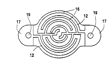
heating element 14 25 shown in figure l(b) having a
thin wafer like body 15 of substantially cir_ular cross
section and two tabs 17 extending from the body 15. A
serpentine pattern of grooves 16 as shown in figure
l(c) are machined through the graphite layer 12 to
expose the underlying boron nitride plate 10 for
forming a continuous strip of pyrolytic graphite 12
exten~;ng from the tabs 17 in an electrical series
circuit relationship. Holes 19 are drilled through the
tabs 17 for attaching the post connectors 21 as shown
in figures 2 and 3.
The post connectors 21 include graphite posts 22
and 23 and graphite screws 24 and 25. The graphite
posts have threaded holes 26 and 27 at one end to
receive the screws 24 and 25 and have an internal

~ W094/08436 2 1 ~i 3 ~ ~ PCT/US93/090~3
tapped hole 28 and 29 at the opposite end for
attachment to an external power supply (not shown). A
pair of flexi~le graphite washers 30 and 31 are
preferably used with each post connector 21 and are
placed on opposite sides of each tab 17 to provide a
solid physical and electrical attachment between each
post connector 21 and the heating element 14. Flexible
graphite is made from particles of graphite
intercalated in an acid solution and exfoliated as
taught in US Patent No.3,404,061,
The posts 22
and 23 are of a leng.h L sof~1cient to separate the
point of electrical contact between the heating element
14 and the external power supply such that the
temperature at the ends 35 of the posts 22 and 23 where
attachment is made with the power supply is
substantially below the tem~erature at the surface of
the heating element 14. A length L of between 1-3
inches is accepta~le. The assembled heating element 14
and post connectors 21 are then preferably coated with
a pyrolytic boron nitride layer to encapsulate the
heating element 14 and post connectors 21 witn the
exception of the tapped holes 28 and 29 which are left
uncoated for attachment to the external power supply.
Alternatively, the contact ends 35 of the post
connectors 21 may be masked to provide an alternative
connection to the power supply.
~'

Representative Drawing
A single figure which represents the drawing illustrating the invention.
Administrative Status

2024-08-01:As part of the Next Generation Patents (NGP) transition, the Canadian Patents Database (CPD) now contains a more detailed Event History, which replicates the Event Log of our new back-office solution.

Please note that "Inactive:" events refers to events no longer in use in our new back-office solution.

For a clearer understanding of the status of the application/patent presented on this page, the site Disclaimer , as well as the definitions for Patent , Event History , Maintenance Fee  and Payment History  should be consulted.

Event History

Description Date
Inactive: Agents merged 2013-08-13
Inactive: IPC from MCD 2006-03-11
Time Limit for Reversal Expired 2004-09-24
Letter Sent 2003-09-24
Inactive: Correspondence - Prosecution 1999-02-24
Grant by Issuance 1999-01-12
Pre-grant 1998-09-22
Inactive: Final fee received 1998-09-22
Notice of Allowance is Issued 1998-05-04
Letter Sent 1998-05-04
Inactive: Status info is complete as of Log entry date 1998-04-27
Inactive: Application prosecuted on TS as of Log entry date 1998-04-27
Inactive: Adhoc Request Documented 1998-04-21
Inactive: Approved for allowance (AFA) 1998-03-31
Inactive: Delete abandonment 1998-02-19
Inactive: Abandoned - No reply to s.30(2) Rules requisition 1997-10-28
Amendment Received - Voluntary Amendment 1997-10-28
Inactive: S.30(2) Rules - Examiner requisition 1997-04-28
All Requirements for Examination Determined Compliant 1995-09-27
Request for Examination Requirements Determined Compliant 1995-09-27
Application Published (Open to Public Inspection) 1994-04-14

Abandonment History

There is no abandonment history.

Maintenance Fee

The last payment was received on 1998-09-16

Note : If the full payment has not been received on or before the date indicated, a further fee may be required which may be one of the following

  • the reinstatement fee;
  • the late payment fee; or
  • additional fee to reverse deemed expiry.

Patent fees are adjusted on the 1st of January every year. The amounts above are the current amounts if received by December 31 of the current year.
Please refer to the CIPO Patent Fees web page to see all current fee amounts.

Fee History

Fee Type Anniversary Year Due Date Paid Date
MF (application, 4th anniv.) - standard 04 1997-09-24 1997-09-24
MF (application, 5th anniv.) - standard 05 1998-09-24 1998-09-16
Final fee - standard 1998-09-22
MF (patent, 6th anniv.) - standard 1999-09-24 1999-09-02
MF (patent, 7th anniv.) - standard 2000-09-25 2000-09-05
MF (patent, 8th anniv.) - standard 2001-09-24 2001-08-31
MF (patent, 9th anniv.) - standard 2002-09-24 2002-09-03
Owners on Record

Note: Records showing the ownership history in alphabetical order.

Current Owners on Record
ADVANCED CERAMICS CORPORATION
Past Owners on Record
MICHAEL HENRY SR. GILBERT
TIMOTHY JAMES HEJL
Past Owners that do not appear in the "Owners on Record" listing will appear in other documentation within the application.
Documents

To view selected files, please enter reCAPTCHA code :


To view images, click a link in the Document Description column. To download the documents, select one or more checkboxes in the first column and then click the "Download Selected in PDF format (Zip Archive)" or the "Download Selected as Single PDF" button.

List of published and non-published patent-specific documents on the CPD .

If you have any difficulty accessing content, you can call the Client Service Centre at 1-866-997-1936 or send them an e-mail at CIPO Client Service Centre.


Document
Description 
Date
(yyyy-mm-dd) 
Number of pages   Size of Image (KB) 
Description 1998-03-03 5 202
Claims 1998-03-03 2 48
Representative drawing 1999-01-12 1 10
Representative drawing 1997-06-17 1 8
Drawings 1996-05-14 2 40
Description 1996-05-14 5 273
Claims 1996-05-14 2 66
Abstract 1996-05-14 1 54
Commissioner's Notice - Application Found Allowable 1998-05-03 1 164
Maintenance Fee Notice 2003-11-18 1 173
Correspondence 1998-09-21 1 50
Fees 1998-09-15 1 44
Correspondence 1999-04-15 1 10
Fees 1997-09-23 1 52
Fees 1996-09-17 1 34
Fees 1995-10-11 1 42
Fees 1995-10-08 1 36
National entry request 1995-01-26 3 115
National entry request 1995-07-27 3 107
International preliminary examination report 1995-01-26 9 253
Examiner Requisition 1997-04-27 2 67
Prosecution correspondence 1995-09-26 1 50
Prosecution correspondence 1995-01-26 8 300
Courtesy - Office Letter 1995-06-21 1 20
Prosecution correspondence 1997-10-27 2 69