Note: Descriptions are shown in the official language in which they were submitted.
21~1385
211PUS05259
OPEN LOOP MIXED REFRIGERANT CYCLE FOR ETHYLENE RECOVERY
FIELD OF THE INVENTION
This invention pertains to the recovery of ethylene from light
gases at cryogenic temperatures, and in particular to an open loop mixed
refrigerant cycle to provlde refrigeration for such recovery.
BACKGROUND OF THE INVENTION
The recovery of ethylene from crude light hydrocarbon gas mixtures
is an economically important but highly energy intensive process.
Cryogenic separation methods are commonly used which require large
amounts of refrigeration at low temperatures, and the development of
methods to reduce the power consumption for this refrigeration is of
continuing importance in the petrochemical industry.
Ethylene is recovered from light gas mixtures such as cracked gas
from hydrocarbon crackers which contain various concentrations of
hydrogen, methane, ethane, ethylene, propane, propylene, and minor
amounts of higher hydrocarbons, nitrogen, and other trace components.
Refrigeration for condensing and fractionating such mixtures is commonly
provided at successively lo~er temperature levels by ambient cooling
~ water, closed cycle propylene and ethylene systems, and work expansion
or Joule-Thomson expansion of pressurized light gases produced in the
separation process. Numerous designs have been developed over the years
using these types of refrigeration as characterized in representative
U.S. Patents 3,675,435, 4,002,042, 4,163,652, 4,629,4~34, 4,900,347, and
5,035,732.
25- The use of mixed refrigerant systems can be integrated with one or
more of the above-mentioned refrigeration methods to improve the overall
energy efficiency of ethylene recovery. Mixed refrigerants for such
systems typically comprise methane, ethane, ethylene, propane,
propylene, and optionally other light components. Mixed refrigerants
21~1385
-- 2 --
exhibit the desirable property of condensing over a range of
temperatures, which allows the design of heat exchange systems which are
thermodynamically more efficient than single refrigerant systems.
U.S. Patent 4,072,485 describes a closed-loop mixed refrigerant
cycle for providing low level refrigeration in a natural gas processing
plant, or in the cryogenic section of an ethylene plant which utilizes
one or more partial condensation zones to cool feed gas. In this cycle,
the mixed refrigerant is half condensed with cooling water or air at
near ambient temperature and then totally condensed at +50~F and
subcooled to about -25~F with several levels of propane or propylene
refrigeration. In ethylene plant service, the mixed refrigerant is then
utilized to provide refrigeration over the temperature range of -40~F
to -148~F, i.e., it is confined to the same temperature range as the
ethylene refrigeration it replaces. A more specific example of this
cycle of ethylene plant service is described in an article by Victor
Kaiser, et al., "Mixed Refrigerant for Ethylene", in the October 1976
issue of Hydrocarbon Processinq, pages 129-131.
U.S. Patent 4,720,293 describes a process for recovering ethylene
from refinery off-gas which utilizes a closed-loop mixed refrigerant
cycle. In this process, the mixed refrigerant is utilized in a single
heat exchanger to provide refrigeration over a relatively warm
temperature range of +60~F to -85~F. Refrigeration at lower
temperature levels is supplied by vaporization of separated ethane at
low partial pressure and high total pressure, and by work expansion of
light gases which are typically rejected to fuel along with the ethane.
With the conventional process technology described above, the feed
gas chilling and demethanizing must be carried out at pressures in the
range of 450 to 650 psia in order to achieve high ethylene recovery (99%
or more) because the propylene/ethylene cascade system can provide
refrigeration no colder than -150~F for feed gas chilling and for
demethanizer column condenser refrigeration. The amount of
refrigeration for feed cooling below -150~F which can be produced from
other process streams in an ethylene plant is limited by operating
constraints such as the amount of high pressure hydrogen recovered and
21~1385
-
-- 3 --
the fuel system pressure(s). These constraints limit the amount of
expander refrigeration which can be produced, which in turn limits the
ethylene recovery. Pressures between 450 and 650 psia are required in
the feed gas chilling train and in the demethanizer column so that most
of the ethylene can be condenséd above -150~F, and so that sufficient
fuel gas expansion refrigeration at colder temperatures is available to
condense most of the remaining ethylene and achieve low ethylene loss in
the demethanizer column overhead vapor.
The integration of improved mixed refrigerant cycles with
conventional intermediate and low temperature refrigeration holds
promise for further reduction of energy consumption in ethylene
recovery. In particular, it is desirable to improve the efficiency of
refrigeration at the lowest temperature levels required for high
ethylene recovery. The invention described in the following
specification and defined in the appended claims provides a unique open
loop mixed refrigeration cycle for efficient ethylene recovery.
SUMMARY OF THE INVENTION
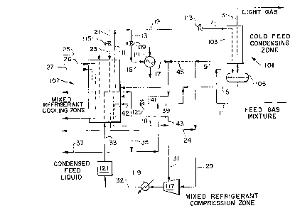
The present invention as illustrated in the accompanying drawings
is a refrigeration method for the recovery of ethylene in which an
ethylene-containing mixed gas stream comprising hydrogen, methane,
ethane, and ethylene is cooled in a cold feed condensing zone (101) to
yield at least one cold feed condensate (5) and a light gas stream (3).
The cold feed condensate (5) is subcooled by indirect heat exchange in a
mixed refrigerant cooling zone (107) with one or more cold process
streams to yield a subcooled condensate (11). A first portion (13) of
the subcooled condensate (11) is flashed and the resulting flashed
stream (15) provides overhead condenser refrigeration for at least one
of the demethanizer columns by indirect heat exchange, which warms and
at least partially vaporizes the resulting flashed stream (15) to yield
a demethanizer overhead condenser refrigerant outlet stream (17). A
second portion (19) of the subcooled condensate (11) is flashed to
provide at least a portion of the refrigeration required to cool the
ethylene-containing mixed gas stream and to condense a portion thereof
by indirect heat exchange in the cold feed condensing zone (101), which
21/41385
-- 4 --
warms and at least partially vaporizes the second portion (19) of
subcooled condensate to yield a cold feed condensing zone refrigerant
outlet stream (9).
The ethylene-containing mixed gas stream typically contains
ethylene, hydrogen, and C1 to C3 hydrocarbons. The cold feed
condensing zone (101) comprises at least one dephlegmator, or at least
one partial condenser, or a combination thereof.
Optionally, a third portion (21) of the subcooled condensate (11)
is flashed and used to provide at least a portion of the refrigeration
required to subcool the cold feed condensate (5) by indirect heat
exchange in the mixed refrigerant cooling zone (107), which warms and at
least partially vaporizes the resulting flashed subcooled condensate
(23). Cooling in the mixed refrigerant cooling zone (107) preferably is
provided by work expanding at least a portion of the light overhead
product from the one or more demethanizer columns. Further cooling
optionally is provided by a hydrogen-rich vapor stream and one or more
methane-rich streams which are obtained by further cooling and partially
condensing at least a portion of the light gas stream (3).
Open loop refrigeration is provided for the demethanizer overhead
condenser (111) and the feed cooling and condensing steps by compressing
one or more mixed refrigerant vapor streams in a mixed refrigerant
compression zone (117) and cooling the resulting compressed stream to
yield a partially condensed mixed refrigerant stream (33), and further
condensing the stream by indirect heat exchange with one or more
additional cold process streams in the mixed refrigerant cooling zone
(107). A first portion (39) of the resulting further condensed mixed
refrigerant (35) is combined with the cold feed condensate (5) from the
cold feed condensing zone (101). A second portion (41) of the further
condensed mixed refrigerant (35) is flashed, warmed in mixed refrigerant
cooling zone 107 to provide refrigeration, and is thereby vaporized to
yield a mixed refrigerant cooling zone second outlet vapor (43). A
third portion (37) of said further condensed mixed refrigerant (35) is
withdrawn for ethylene product recovery.
214138S
-- 5 --
Low pressure inlet refrigerant for the mixed refrigerant
compression zone (117) is provided by the cold feed condensing zone
refrigerant outlet stream (9) and optionally by the mixed refrigerant
cooling zone first outlet vapor (18). Intermediate pressure inlet
refrigerant for the mixed refrigerant compression zone (117) is provided
by the mixed refrigerant cooling zone second outlet vapor (43) and
optionally by the mixed refrigerant cooling zone first outlet vapor
(18).
In an alternative embodiment, the ethylene-containing mixed gas
feed stream (51) to the cold feed condensing zone (101) is provided
optionally by cooling the feed gas mixture (1) and condensing a portion
thereof in a warm feed condensing zone (125) to yield the ethylene-
containing mixed gas feed stream (51) and a warm feed condensate (49).
The warm feed condensing zone (125) comprises at least one dephlegmator,
or at least one partial condenser, or a combination thereof. The warm
feed condensate (49) is flashed to provide at least a portion of the
refrigeration for the cooling and condensing of the feed gas mixture (1)
by indirect heat exchange with the resulting flashed warm feed
condensate (50), thereby vaporizing the flashed feed condensate to yield
a warm feed condensing zone refrigerant vapor (53). Additional
intermediate pressure inlet refrigerant is provided to the mixed
refrigerant compression zone (117) by the warm feed condensing zone
refrigerant vapor (53).
Optionally, at least a portion (20) of the demethanizer overhead
condenser refrigerant outlet stream (17) is combined with the resulting
flashed warm feed condensate (50) to provide additional refrigeration to
the warm feed condensing zone (125).
A key feature of the present invention is that the feed chilling
train, open loop refrigeration cycle, and downstream equipment for
separation of the condensed feed liquids can be operated in the pressure
range of 150 to 400 psia, thereby achieving satisfactory ethylene
recovery with lower refrigeration requirements and lower capital costs
in the downstream separation equipment compared with operation at
conventional pressures in the range of 450 to 600 psia.
~1~ 1385
The present invention thus utilizes an efficient mixed refrigerant
system for ethylene feed condensation in which the system operates in an
open loop mode wherein the mixed refrigerant is provided by components
in the ethylene-containing feed gas.
BRIEF DESCRIPTION OF THE DRAWINGS
Fig. 1 is a schematic flow diagram of the present invention which
utilizes an open loop mixed refrigerant with one feed cooling and
condensation zone.
Fig. 2 is a schematic flow diagram of the present invention which
utilizes an open loop mixed refrigerant with two feed cooling and
condensation zones.
DETAILED DESCRIPTION OF THE INVENTION
Essentially all ethylene plants, and some ethylene recovery
processes, use an ethylene-propylene cascade refrigeration system to
provide the predominant amount of refrigeration required in the ethylene
plant. Most of the propylene (high level) refrigeration is utilized at
several pressure/temperature levels in the initial feed precooling and
fractionation sections of the plant, to cool the feed gas from ambient
temperature to about -35~F and to condense the ethylene refrigerant at
about -30~F. Similarly, the ethylene (low level) refrigeration is
utilized at several pressure/temperature levels in the cryogenic section
of the plant to cool the feed from -35~F to about -145~F in order to
condense the bulk of the ethylene in the form of liquid feeds to one or
more demethanizer columns, and is used in at least one of the
demethanizer column overhead condenser(s) at about -100~F to -235~F to
provide reflux to the column(s). Ethylene is normally not used to
provide refrigeration below -150~F since that would result in sub-
atmospheric pressure at the suction of the ethylene compressor.Refrigeration below -150~F to condense the remaining ethylene from the
feed gas is provided primarily by work expansion of hydrogen- and
methane-containing light gas streams and/or by vaporization of methane
refrigerant which has been condensed by ethylene refrigerant. The work
expanded gases are normally used as fuel and consist primarily of the
2141385
overhead vapor from the demethanizer column, mostly methane, and any
uncondensed feed gas, mostly H2 and methane, which is not processed in a
H2 recovery section of the ethylene plant or ethylene recovery process.
Refrigeration also may be recovered from one or more of the hydrogen-
rich and methane-rich streams produced in a hydrogen recovery section.
Cooling and condensation of the feed gas preferably is
accomplished by dephlegmation in a dephlegmator, which is a rectifying
heat exchanger which partially condenses and rectifies the feed gas.
Typically a dephlegmator yields a degree of separation equivalent to
multiple separation stages, typically 5 to 15 stages. Alternatively,
cooling and condensation of the feed gas is accomplished in a
conventional condenser, defined herein as a partial condenser, in which
a feed gas is partially condensed to yield a vapor-liquid mixture which
is separated into vapor and liquid streams in a simple separator vessel.
A single stage of separation is realized in a partial condenser.
With the conventional process technology described above, the feed
gas chilling and demethanizing must be carried out at pressures in the
range of 450 to 650 psia in order to achieve high ethylene recovery (99%
or more) because the propylene/ethylene cascade system can provide
refrigeration no colder than -150~F for feed gas chilling and for
demethanizer column condenser refrigeration. The amount of
refrigeration for feed cooling below -150~F which can be produced from
other process streams in an ethylene plant is limited by operating
constraints such as the amount of high pressure hydrogen recovered and
the fuel system pressure(s). These constraints limit the amount of
expander refrigeration which can be produced, which in turn limits the
ethylene recovery. Pressures between 450 and 650 psia are required in
the feed gas chilling train and in the demethanizer column so that most
of the ethylene can be condensed above -150~F, and so that sufficient
fuel gas expansion refrigeration at colder temperatures is available to
condense most of the remaining ethylene and achieve low ethylene loss in
the demethanizer column overhead vapor.
The present invention comprises an open-loop mixed refrigerant
35 cycl e designed to provide the refrigeration required for cooling
214138~
ethylene plant or other ethylene recovery process feed gas in the range
of about -20~F to -220~F. Feed gas is cooled and condensed in part in
one or more feed cooling/condensing zones and preferably at least one of
the cooling/condensing zones is a dephlegmator. Alternatively, at least
one of the cooling/condensing zones is a partial condenser.
Alternatively, a combination of one or more dephlegmators and partial
condensers can be used in the cooling/condensing zones. In an
embodiment having two cooling/condensing zones, liquid condensed in a
warmer cooling/condensing zone, e.g., a partial condenser, is optionally
subcooled, flashed to an intermediate pressure (50 to 250 psia),
vaporized and warmed to provide the warm level refrigeration required
for the process. Liquid condensed in the cold cooling/condensing zone,
e.g., a dephlegmator, is optionally subcooled, flashed to low pressure
(15 to 50 psia), vaporized and warmed to provide the cold level
refrigeration required for the process. One or more intermediate level
feed cooling/condensing zones can be added to produce additional
condensed feed liquid streams to be vaporized and warmed (at additional
pressure levels, if desirable) to provide intermediate level
refrigeration for the process. Any of these condensed feed liquid
streams can be supplemented as necessary with additional mixed
refrigerant from the open-loop cycle to increase the amount of
refrigeration available for any feed or mixed refrigerant
cooling/condensing zone or to increase the amount of refrigeration
available for a demethanizer condenser. Refrigeration for one or more
demethanizer column condensers may be supplied by any of the condensed
feed liquid streams in series and/or in parallel with any of the feed
cooling/condensing zones or mixed refrigerant cooling/condensing zones.
All of the liquids condensed from the feed gas are ultimately removed
from the open-loop cycle to recover an ethylene product and are normally
separated in a fractionation unit, typically after first being processed
in one or more demethanizer columns to remove methane and other light
gases.
The cooling, condensation, and open loop refrigeration steps can
be operated advantageously in the range of 150 to 400 psia, and the feed
gas mixture can be provided at a pressure of 150 to 400 psia. Cooling
21413~5
g
and condensation of the feed gas preferably is accomplished by
dephlegmation in a dephlegmator, which is a rectifying heat exchanger
which partially condenses and rectifies the feed gas. Typically a
dephlegmator yields a degree of separation equivalent to multiple
separation stages, typically 5 to 15 stages. Alternatively, cooling and
condensation of the feed gas is accomplished in a conventional
condenser, defined herein as a partial condenser, in which a feed gas is
partially condensed to yield a vapor-liquid mixture which is separated
into vapor and liquid streams in a simple separator vessel. A single
stage of separation is realized in a partial condenser.
A first embodiment of the invention is described in detail by the
schematic flowsheet of Fig. 1. Feed gas mixture 1, obtained for example
by initial cooling and separation of cracked gases from a hydrocarbon
cracking unit, is typically at -20~F to -80~F and 200 to 550 psia, but
can be provided in the range of 150 to 400 psia. The feed gas typically
contains hydrogen, methane, ethane, ethylene, propane, propylene, and
other minor components at low concentrations. The actual composition
will depend on the hydrocarbon cracking feedstock and degree of
pretreatment; typical composition ranges are 5 to 40 mole% hydrogen, 5
to 40 mole% methane, 5 to 40% ethylene, 5 to 30 mole% ethane, lower
concentrations of propane, propylene, and heavier hydrocarbons, and
lower concentrations of nitrogen and carbon monoxide. Feed gas mixture
1 is cooled and condensed in part in cold feed condensing zone 101,
preferably utilizing a dephlegmator, to yield light gas 3 comprising
chiefly hydrogen and methane and feed condensate 5 enriched in C2 and
heavier hydrocarbons. Zone 101 is shown as dephlegmator 103 and liquid
accumulator 105. Refrigerant stream 7, described later, provides
refrigeration at -180~ to -235~F by indirect heat exchange in
dephlegmator 103 and is at least partially vaporized to yield cold feed
condensing zone refrigerant outlet stream 9. In cold feed condensing
zone 101, dephlegmator 103 rectifies feed gas mixture 1 in an equivalent
5 to 15 stages of separation which reduces ethylene losses in light gas
stream 3 and reduces the light component content (mostly methane) of
feed condensate 5, thereby increasing overall ethylene recovery and
purity. Feed condensate 5 at about -25~F to -100~F is subcooled in
21~1385
- 10 -
mixed refrigerant cooling zone 107 by indirect heat exchange with cold
streams defined later to yield subcooled condensate 11 at about -175~ to
-225~F. Alternatively, cold feed condensing zone 101 is a single-stage
partial condenser.
A first portion 13 of subcooled condensate 11 is flashed to 15 to
250 psia across pressure reducing valve 109 to provide refrigerant as
resulting flashed stream 15 at about -100~F to -235~F to demethanizer
column overhead condenser 111, yielding at least partially vaporized
demethanizer overhead condenser refrigerant outlet stream 17. A second
portion 19 of subcooled condensate 11 is flashed to 15 to 50 psia across
pressure reducing valve 113 to provide refrigerant stream 7 at -180~ to
-235~F to dephlegmator 103. Optionally, a third portion 21 of subcooled
condensate 11 is flashed to 15 to 50 psia across pressure reducing valve
115 to provide flashed subcooled condensate 23 as a refrigerant at -180~
to -235~F to mixed refrigerant cooling zone 107. Additional
refrigeration is provided to mixed refrigerant cooling zone 107 by cold
process streams 25, 26, and 27, typically available at -175~ to -235~F,
which supply the major portion of the refrigeration to mixed refrigerant
cooling zone 107. These cold streams, which are produced in other
sections of the ethylene plant (not shown), may include work-expanded
light gas overhead from a demethanizer column, work-expanded light gas
separated from the feed gas, as well as cold methane and hydrogen
streams from a hydrogen recovery section of the plant. The flow rate of
flashed subcooled condensate 23 is controlled to balance the total
amount of refrigeration required to subcool the high pressure mixed
refrigerant, and to compensate for variations in the properties of cold
process streams 25, 26, and 27. Additional cold process streams (not
shown) can be used to supplement refrigeration from the described cold
process streams 25, 26, and 27. Typically about 60 to 100% of the total
refrigeration for mixed refrigerant cooling zone 107 is provided by cold
process streams 25, 26, and 27; the remainder is provided by flashed
subcooled refrigerant 23 and supplemental flashed refrigerant stream 42.
Mixed refrigerant cooling zone 107 comprises one or more
conventional type cooling and condensing heat exchangers.
21~1385
-
- 11 -
The remainder of the refrigeration cycle in this embodiment of the
invention comprises an open-loop mixed refrigerant system driven by
mixed refrigerant compression zone 117 which compresses one or more
refrigerant vapor streams comprising methane, ethane, ethylene, and
heavier hydrocarbons condensed from the feed gas. Mixed refrigerant
compression zone 117 comprises a single-stage or preferably multi-stage
compressor of the axial or centrifugal type. Preferably the compressor
is a multi-stage type which operates with multiple inlet streams,
typically with a low pressure vapor stream introduced into the first
stage and an intermediate pressure vapor stream introduced at an
interstage location. Low pressure mixed refrigerant vapor 29 at 15 to
50 psia and optionally intermediate pressure mixed refrigerant vapor 31
at 50 to 250 psia are compressed to 200 to 550 psia, or alternatively to
150 to 400 psia, cooled in cooling water exchanger 119 to yield cooled
compressed refrigerant 32, and further cooled and partially condensed in
propane or propylene refrigeration system 121. The resulting partially
condensed mixed refrigerant stream 33, now at about -20~F to -50~F, is
further cooled and condensed in mixed refrigerant cooling zone 107 to
yield mixed refrigerant 35 at about -50~F to -125~F.
Refrigeration for condensing mixed refrigerant stream 33 is
provided in part by warming partially vaporized demethanizer overhead
condenser refrigerant outlet stream 17 in mixed refrigerant cooling zone
107 to yield mixed refrigerant cooling zone first outlet vapor 18.
Additional refrigeration is provided by cold process streams earlier
defined.
A portion 37 of mixed refrigerant 35, equivalent in flow to feed
condensate 5, is withdrawn for recovery of ethylene product and further
purification in the fractionation section of the plant. Another portion
39 optionally is combined with feed condensate 5 to provide additional
refrigerant for cold feed condensing zone 101 and demethanizer overhead
condenser 111. A third portion 41 optionally is flashed to 50 to 250
psia across pressure reducing valve 125 to provide additional
refrigeration to mixed refrigerant cooling zone 107. Vaporizàtion of
flashed portion 42 yields mixed refrigerant cooling zone second outlet
~1~13~5
- 12 -
vapor 43 which provides at least a portion of intermediate pressure
mixed refrigerant vapor 31 to mixed refrigerant compression zone 117.
Optionally, refrigerant 23 is warmed in mixed refrigerant
cooling zone 107 to provide additional refrigeration thereby yielding
vaporized mixed refrigerant 24. Vaporized mixed refrigerant 24 is
combined with cold feed condensing zone refrigerant outlet stream 9 to
provide low pressure mixed refrigerant vapor 29 to mixed refrigerant
compression zone 117. When subcooled condensate 13 is flashed across
pressure reducing valve 109 to an intermediate pressure of 50 to 250
psia, mixed refrigerant cooling zone first outlet vapor 18 is combined
with mixed refrigerant cooling zone second outlet vapor 43 to provide
intermediate pressure mixed refrigerant vapor 31 to mixed refrigerant
compression zone 117. When subcooled condensate 13 is flashed across
pressure reducing valve 109 to a low pressure of 15 to 50 psia, mixed
refrigerant cooling zone first outlet vapor 18 is combined (not shown)
with cold feed condensing zone refrigerant outlet stream 9 to provide
low pressure mixed refrigerant feed 29 to mixed refrigerant compression
zone 117.
Optionally, at least a portion 45 of cold feed condensing zone
refrigerant outlet stream 9 may be combined with partially vaporized
demethanizer condenser refrigerant outlet stream 17 to provide
additional refrigeration to mixed refrigerant cooling zone 107. This
option is preferred if outlet stream 9 is only partially vaporized.
An alternative embodiment of the invention is given in Fig. 2 in
which the cold feed condensing zone 101 is preceded by warm feed
condensing zone 125. Feed gas mixture 1 is typically at -20~F to -80~F
and 200 to 550 psia, but can be provided in the range of 150 to 400
psia. Feed gas mixture 1 is initially cooled to -50~F to -125~F and is
partially condensed in warm feed condensing zone 125, which may be a
partial condenser consisting of cooling exchanger 127 and separator 129.
Partially condensed feed 47 is separated into warm feed condensate 49
and ethylene-containing mixed gas stream 51. Stream 51 provides the
feed to cold feed condensing zone 101, which preferably is dephlegmator
103 as described in the first embodiment of the invention given in Fig.
1. Warm feed condensate 49 is flashed to 50 to 250 psia across pressure
214I38S
- 13 -
reducing valve 131 to yield flashed warm feed condensate 50 which
provides at least a portion of the refrigeration needed to cool feed gas
mixture 1 by indirect heat exchange in warm feed condensing zone 125.
Vaporized refrigerant stream 53 provides additional intermediate
pressure mixed refrigerant vapor 31 to mixed refrigerant compression
zone 117.
Optionally, additional refrigeration for warm feed condensing zone
125 is provided by flashing another portion 55 of mixed refrigerant
liquid 35 across pressure reducing valve 133 and combining the flashed
refrigerant with flashed feed condensate 50 downstream of pressure
reducing valve 131. Optionally, additional refrigeration for warm feed
condensing zone 125 is provided by combining at least a portion 20 of
partially vaporized demethanizer overhead condenser refrigerant outlet
stream 17 with flashed feed condensate 50. The remaining portion of the
mixed refrigerant cycle of Fig. 2 is essentially the same as in the
corresponding portion of Fig. 1.
Subcooling of mixed refrigerant liquid 11 to about -175~F to
-225~F in the present invention is highly advantageous in ethylene
plants in order to provide sufficiently cold refrigeration to cool the
feed gas to -170~F to -220~F, which is the temperature range required
for high (99+%) or ultra-high (99.75+%) ethylene recovery. To attain
these high ethylene recoveries, feed gas must typically be cooled to
-190~F to -220~F in ethylene plants utilizing conventional partial
condensers, or -170~F to -190~F in ethylene plants utilizing
dephlegmators.
While the embodiment illustrated in Fig. 2 utilizes a combination
of a partial condenser and a dephlegmator for feed cooling and
condensing, any combination of these two types of condensing systems can
be utilized. Alternatively, combinations of one or more partial
condensers and one or more dephlegmators operated in series could be
utilized. For example, three partial condensers or dephlegmators could
be used in series; in this option, refrigeration for demethanizer column
overhead condenser 111 could be provided by a mixed refrigerant stream
in parallel with the refrigeration for the intermediate partial
condenser(s) or intermediate dephlegmator(s) or in parallel with the
211I385
- 14 -
cold partial condenser or cold dephlegmator to best match the required
refrigeration temperature levels. In addition, demethanizer column
overhead condenser 111 could be replaced with a dephlegmator or could
consist of a dephlegmator operating in series with a partial condenser
or other combinations. In any case, refrigeration for these heat
exchangers would be provided by the appropriate open-loop mixed
refrigerant streams ta best match the temperature levels.
Optionally, one or more of the various liquid streams condensed
from the feed gas could be completely segregated in the open-loop mixed
refrigerant cycle and compressed in a separate compressor(s) in order to
produce two or more liquid streams of different composition for feeds to
different downstream processing units, such as two demethanizer columns
or a de-ethanizer column and a demethanizer column. Any of the warmed
refrigerant streams 9, 18, 29, 31, 43, and 53 which are not completely
vaporized can be further warmed to provide refrigeration in other parts
of the ethylene recovery process, such as a second demethanizer column
overhead condenser or a warm feed condensing heat exchanger.
With propylene refrigeration and the open-loop mixed refrigerant
cycle of the present invention, the amount of refrigeration and the
coldest temperature level at which it can be provided are not limited by
the amount of high pressure H2 recovered or by the fuel system
pressure(s). Therefore, high levels of ethylene recovery in the present
invention can be achieved with much lower feed gas pressures, in the
range of 150 to 400 psia, than in conventional ethylene recovery
systems. The colder refrigeration provided by the mixed refrigerant
cycle also can be used to reduce the amount of ethylene lost in the
overhead of the demethanizer column and further increase ethylene
recovery. In addition, the colder refrigeration provided by the mixed
refrigerant cycle also permits the downstream demethanizer column(s) to
be operated at pressures lower than the conventional 400 to 500 psia
level required for high ethylene recovery when ethylene refrigeration is
utilized as the overhead condenser refrigerant. At lower pressures,
separation of methane and lighter gases from ethylene and heavier
hydrocarbons is easier, resulting in lower refrigeration requirements
and lower equipment costs in the demethanizer column system. This low
21~1385
,
- 15 -
pressure feed gas chilling concept with propylene refrigeration and the
open-loop mixed refrigerant system can also be used to recover ethylene,
ethane, and/or heavier hydrocarbons from refinery or petrochemical
off-gases. Other refrigerants, such as propane, ammonia or various
freons, could be used to supply high-level refrigeration in place of
propylene for feed gas precooling and for condensing the mixed
refrigerant. An absorption refrigeration system could also be used to
supplement any of these high-level refrigerants.
This open-loop mixed refrigerant cycle also can be used to recover
ethylene, ethane or heavier hydrocarbons from a refinery or
petrochemical off-gas. Other refrigerants, such as ammonia or various
freons, could be used in place of propane or propylene to supply high
level refrigeration for feed gas cooling and for condensing the mixed
refrigerant.
EXAMPLE
A mass and energy balance was carried out to illustrate the
embodiment of the invention as described by Fig. 2. Ethylene plant feed
gas mixture 1 at a flow rate of 13,147 lb moles per hour and 500 psia
containing 18 mole% hydrogen, 35 mole% methane, 36 mole% ethylene, and
11 mole% ethane plus heavier hydrocarbons is cooled from -32~F to -75~F
in warm feed condensing zone 125 which is a partial condenser. The
partially condensed feed stream 47 is separated into vapor stream 51 and
liquid stream 49. Vapor stream 51 containing 31.5 mole% hydrogen, 45.5
mole% methane, 19 mole% ethylene, and 4 mole% ethane is further cooled
to -172~F in cold feed condensing zone 101 which is a dephlegmator to
condense and rectify most of the remaining ethylene, which is recovered
in feed condensate 5. Overall, more than 99.75% of the ethylene in the
feed gas is recovered in the two liquid streams 5 and 49. That is, less
than 0.25% of the ethylene in the feed gas stream 1 is lost in the
dephlegmator overhead light gas stream 3.
The liquid stream 49 condensed in feed heat exchanger 127 is
flashed to 180 psia to yield flashed stream 50 at -100~F, which is
vaporized and warmed to -35~F in feed heat exchanger 127 and sent as
stream 53 to mixed refrigerant compression zone 117 along with mixed
21~1385
- 16 -
refrigerant vapor stream 43 at -35~F as combined stream 31 at 178 psia.
The feed condensate 5 from dephlegmator 103 at -90~F is combined with
additional mixed refrigerant 39 at -80~F, subcooled to -180~F in mixed
refrigerant cooler 107 to yield subcooled mixed refrigerant 11, which is
used to provide the cold level refrigeration required for dephlegmator
103 of cold feed condensing zone 101 and demethanizer overhead condenser
111. Vaporized mixed refrigerant stream 9 at -93~F and streams 18 and
24 at -35~F are sent to mixed refrigerant compression zone 117 as
combined stream 29 at 28 psia.
Open-loop mixed refrigerant vapor stream 29 (3720 lb moles per
hour) at -69~F and 28 psia, and mixed refrigerant vapor stream 31 (7435
lb moles per hour at -35~F and 178 psia, are compressed to 503 psia and
the compressor outlet is cooled to 100~F by cooling water in heat
exchanger 119. Cooled mixed refrigerant vapor stream 32, which contains
1 mole% hydrogen, 24% methane, 57% ethylene and 18% ethane plus heavier
hydrocarbons, is further cooled to -32~F with multiple levels of
propylene refrigerant in refrigeration zone 121 to condense about 83% of
the mixed refrigerant to yield stream 33. Stream 33 is then further
cooled to -80~F at 495 psia and totally condensed in mixed refrigerant
cooler 107 against warming H2 and methane streams 25 and 26 available
from the H2 recovery section of the ethylene plant, expander stream 27,
mixed refrigerant stream 42, and mixed refrigerant stream 17 from
demethanizer overhead condenser 111.
About 74% of mixed refrigerant liquid stream 35, equal to the
total amount initially condensed from feed gas 1 in streams 5 and 49, is
withdrawn and sent to a demethanizer column (not shown) as stream 37.
Stream 41, which is about 13% of mixed refrigerant liquid 35, is flashed
to 180 psia, vaporized, and warmed to -35~F in mixed refrigerant cooler
107 to yield vapor stream 43. The remaining 13% of mixed refrigerant
liquid 35, as stream 39, is combined with feed condensate 5 from
dephlegmator 103 of cold feed condensing zone 101, and is subcooled to
-180~F in mixed refrigerant cooler 107 against warming H2, methane, and
expander streams 25, 26, and 27 to yield subcooled mixed refrigerant 11.
About 59% of subcooled mixed refrigerant liquid 11, as stream 19, is
flashed to 30 psia and -200~F, and is vaporized and warmed to -93~F in
- 17- 2 1 4 1 3 8 5
dephlegmator 103 of cold feed condensing zone 101 to yield refrigerant
outlet stream 9. The remaining 41% of subcooled mixed refrigerant
liquid 11, as stream 13, is flashed to 32 psia, and is vaporized and
warmed to -135~F in demethanizer column overhead condenser 111 to
5 provide reflux to that column. The resulting low pressure mixed
refrigerant vapor 17 is further warmed to -35~ F in mixed refrigerant
cooler 107 to yield vapor 18, which is combined with cold feed
condensing zone refrigerant outlet stream 9, and the combined stream 29
is sent to mixed refrigerant compression zone 117 at -69~F and 28 psia.
Supplemental mixed refrigerant stream 43, which is vaporized and warmed
to -35~F i n mixed refrigerant cooling zone 107, and stream 53, which is
vaporized and warmed to -35~F in warm feed condensing zone 125, are
combined as stream 31 and sent to mixed refrigerant compression zone 117
at -35~F and 178 psia. In this Example, low pressure mixed refrigerant
stream 23 and supplemental mixed refrigerant streams 20, 45, and 55 are
not utilized.
In this Example, the open-loop mixed refrigerant-propylene
refrigeration system requires about 10% less compression power at the
same ethylene recovery of 99.75% than a conventional closed loop
20 ethylene-propylene cascade refrigeration system to supply the same
amount of refrigeration for cooling the feed gas from -32~F to -172~F.
With a relatively small increase in compression power, ethylene recovery
could be increased from 99.75% to 99.9% using the open-loop mixed
refrigerant-propylene refrigeration system. This level of ethylene
25 recovery would not be possible with the conventional ethylene-propylene
refrigeration system within the operating constraints of the ethylene
plant of this Example.
The closed-loop mixed refrigerant cycle described in earlier-cited
U.S. Patent 4,072,485 assigned to Technip is intended to provide low
30 level (below -40~ F) refrigeration in a natural gas processing plant or
in the cryogenic section of a conventional (cracked gas) ethylene plant,
which employs one or more partial condensation zones to cool and
condense cracked gas feed to the demethanizer column. In the '485
cycle, the mixed refrigerant is more than half condensed at near ambient
35 temperature with water or air and is totally condensed at +50~F with
2 1~138$
- 18 -
one or more levels of warm propane or propylene refrigerant. The mixed
refrigerant liquid is subcooled to -25~F with one or more levels of
colder propane or propylene refrigerant. In an ethylene plant
application, this subcooled mixed refrigerant liquid is then split into
two portions. One portion is further subcooled to -58~F in a
"secondary" or "auxiliary" heat exchanger against cold process streams
and the remaining portion is further subcooled to -148~F in the "main"
exchanger against returning low pressure mixed refrigerant. The two
subcooled mixed refrigerant streams are then combined, flashed to low
pressure, and utilized to provide refrigeration over the temperature
range of -40~F to -148~F, i.e., the mixed refrigerant is confined to
exactly the same temperature range as the ethylene refrigeration it
replaces. The supply of refrigeration to the demethanizer column
overhead condenser in the ethylene plant is not specifically addressed
in the patent.
The more specific ethylene plant example of the '485 cycle
described in the earlier-cited article by Kaiser, et al., indicates a
power reduction of 9% for the '485 closed-loop mixed refrigerant-
propylene system as compared to a conventional ethylene-propylene
cascade system. However, the '485 system provides feed gas cooling only
to a level of -134~F, which is not sufficient for a modern high-
recovery ethylene plant, and also does not address the supply of
refrigeration to the demethanizer column overhead condenser, which would
normally require refrigeration at the -150~F level. With the '485
closed-loop mixed refrigerant cycle, ethylene recovery is limited to
what could be obtained with the corresponding ethylene refrigeration
cycle, which is well below the 99+% ethylene recovery of most modern
ethylene plants, and far below the 99.75+% ethylene recovery attainable
with dephlegmator-type ethylene plants.
For high levels of ethylene recovery above 99%, it is necessary to
provide refrigeration at much lower temperatures than the -150~F level
attainable with a conventional ethylene refrigeration cycle or with the
'485 closed-loop mixed refrigerant cycle. The amount of refrigeration
for feed cooling below -145~F available from process streams in an
ethylene plant is limited by operating constraints such as the amount of
2141385
- 19 -
high pressure H2 recovered and the fuel system pressure(s). These
constraints limit the amount of expander refrigeration which can be
produced, which, in turn, limits the ethylene recovery. With the open-
loop mixed refrigerant cycle of the present invention, the amount of
refrigeration and the coldest temperature level at which it can be
provided are not limited by these constraints, and high levels of
ethylene recovery up to 99.9% can be achieved economically. Additional
and/or colder refrigeration can be provided by the open-loop mixed
refrigerant cycle by increasing the amount of supplemental low or
intermediate pressure mixed refrigerant which is used to cool the high
pressure mixed refrigerant streams. In addition, the open-loop mixed
refrigerant cycle can provide refrigeration colder than the -150~F
level normally supplied to a demethanizer column overhead condenser by
an ethylene refrigeration cycle. This colder refrigeration can reduce
the amount of ethylene lost in the overhead of the demethanizer column
and further increase ethylene recovery.
The open-loop mixed refrigerant cycle of the present invention
provides much colder refrigeration than the '485 closed-loop mixed
refrigerant cycle for the cryogenic section of an ethylene plant or
other ethylene recovery process. The cryogenic feed cooling section
(below -20~F) preferably uses at least two separate condensing zones
and preferably at least one of these condensing zones is a dephlegmator
to prefractionate the condensed feed liquid before it enters a
downstream fractionation unit, such as a demethanizer column. In the
cycle of the present invention, a major portion of the open-loop mixed
refrigerant is condensed at -20~F to -50~F with refrigeration provided
by one or more levels of propane, propylene or similar refrigerant and
preferably further condensed and/or subcooled to -50~F to -125~F with
refrigeration provided at least in part by ethylene plant cold process
streams. A portion of the mixed refrigerant liquid is preferably
subcooled to about -175~F to -225~F, with the predominant amount of
this refrigeration provided by ethylene plant process streams.
Supplemental refrigeration for mixed refrigerant cooling, condensing and
subcooling may be provided by vaporizing intermediate and/or low
pressure mixed refrigerant streams, to most efficiently balance the
21~1385
- 20 -
refrigeration loads in the cycle and/or to increase the amount of
refrigeration produced. The coldest mixed refrigerant liquid (-175~F
to -225~F) is used to provide refrigeration to the cold feed condensing
zone(s) and to provide refrigeration to a demethanizer column overhead
condenser, if necessary. The warmer mixed refrigerant (-20~F to
-125~F) is used to provide refrigeration to the warm feed condensing
zone(s).
In the cycle of the present invention, the mixed refrigerant is
not totally condensed at +50~F as in the '485 cycle, since this results
in inefficient high pressure levels for the mixed refrigerant stream,
e.g., up to 725 psia in the '485 cycle. Instead, in the present
invention a major portion of the mixed refrigerant is condensed at
-20~F to -50~F, at pressures below 550 psia. This mixed refrigerant
cycle also supplies refrigeration to a demethanizer column overhead
condenser, which requires a significant amount of low level (e.g.,
-125~F to -150~F) refrigeration in a typical ethylene plant.
The earlier-cited closed-loop mixed refrigerant cycle of U.S.
Patent 4,720,293 assigned to Air Products and Chemicals, Inc. supplies
relatively high level refrigeration (+60~F to -85~F) to a single heat
exchanger and relies on vaporization of separated ethane at low partial
pressure to provide intermediate level refrigeration (-85~F to -170~F),
primarily in the demethanizer column overhead condenser. This requires
that the separated ethane be combined with the work expanded H2 and
methane (which provide the lowest level refrigeration) and which are
then typically is sent to fuel after refrigeration recovery. This may
be highly advantageous in processing refinery off-gases when ethane has
no value except as fuel, but would not normally be practical in ethylene
plants, where the separated ethane has a higher value as feedstock than
as fuel, and must be recycled to the cracking furnaces in a relatively
pure state.
In addition to the power savings and significantly higher ethylene
recovery provided by the open-loop mixed refrigerant cycle of the
present invention, significant capital savings can be realized due to
the simplification of equipment with the open-loop mixed refrigerant
cycle, as compared to a conventional ethylene refrigeration cycle.
2111385
- 21 -
Compared to the conventional ethylene cycle, the open-loop cycle of the
present invention requires fewer pieces of equipment and less
interconnecting piping, which results in lower overall cost. In
addition, with the open-loop mixed refrigerant cycle, no refrigerant
make-up is required, as is necessary with a closed-loop cycle. Also,
there is no need to change the mixed refrigerant composition when the
feed gas composition changes, as may be required with a closéd-loop
mixed refrigerant cycle. When the feed gas composition changes, the
mixed refrigerant composition changes automatically with the open-loop
mixed refrigerant cycle.
With the propylene refrigeration and the open-loop mixed
refrigerant cycle of the present invention, the feed gas chilling train
of an ethylene plant or other ethylene recovery unit can be operated in
the range of 150 to 400 psia, eliminating one or two stages of feed gas
compression and eliminating the associated capital cost of these
compression stages. An equivalent amount of compression energy must be
added to the propylene and mixed refrigerant compressors, but these are
incremental increases in the compression stages, with much smaller
associated capital costs. No additional refrigeration compression
stages are required.
Feed gas chilling, and optionally demethanizing as well, can be
carried out at these lower pressure levels while achieving high ethylene
recovery because the propylene/mixed refrigerant cascade system can
provide all of the necessary refrigeration at temperatures colder than
-150~F, regardless of the amount of expander refrigeration available.
The propylene/mixed refrigerant system be supplemented with fuel gas
expander refrigeration, but the amount of expander refrigeration is no
longer a constraint to ethylene recovery.
An ethylene recovery unit utilizing a low pressure chilling train
operated in the range of 150-400 psia with the propylene/open-loop mixed
refrigerant system of the present invention provides additional benefits
compared with conventional ethylene recovery processes. These benefits
include:
21~I385
- 22 -
1) less methane and hydrogen are condensed with the ethylene
and heavier hydrocarbons, resulting in lower flow rates and lower
refrigeration requirements in the demethanizer column(s),
2) more separation of ethylene and ethane is obtained as the
feed gas is condensed, particularly where one or more
dephlegmators are used in the feed chilling train, resulting in
further refrigeration savings in the demethanizer column(s),
3) more hydrogen can be upgraded in purity to a higher value
product since it is not necessary to expand some of the hydrogen
for low-level refrigeration, producing a lower value fuel,
4) where a multi-zone demethanizer column system is used,
more separation of ethylene and ethane in the feed gas chilling
section also results in a reduction in the amount of liquid which
must be processed in the de-ethanizer column, resulting in a lower
flow rate and a savings in separation energy in the de-ethanizer
column,
5) where a multi-zone demethanizer column system is used,
more separation of ethylene and ethane in the feed gas chilling
section also provides more preseparation of the two feed streams
to the ethylene/ethane splitter column, resulting in a further
savings in separation energy,
6) much of the equipment in the feed pretreatment/drying
section, the feed gas chilling train and, optionally, the
demethanizer column(s), is operated at significantly lower
pressure, resulting in reduced capital cost, and
7) due to the lower pressure ratio between the feed gas and
fuel gas, one or more fuel gas expanders are eliminated, further
reducing capital cost.
The open-loop mixed refrigerant cycle utilized in the low pressure
chilling train provides low-level refrigeration (below about -40~F) in
the cryogenic section of an ethylene plant which uses multiple partial
condensation stages or, preferably, dephlegmators or combinations of
partial condensers and dephlegmators in series, operating below about
-30~F, to prefractionate the condensing cracked gas feed before it
enters the demethanizer column system. Compared to a conventional
" 2191385
- 23 -
ethylene refrigeration cycle, the mixed refrigerant cycle provides
significant power savings, higher ethylene recovery and also significant
capital savings due to the simplification of equipment. For example,
the mixed refrigerant compressor has only one or two suction streams,
suction drum, and recycle control loops. The typical ethylene
refrigerant compressor has at least three suction streams, three suction
drums and three recycle control loops, a much more expensive
arrangement. In addition, the mixed refrigerant compressor, with
suction temperatures of -50~F or warmer, can utilize a cheaper
metallurgy than the ethylene refrigerant compressor, which typically has
a suction temperature of -150~F at the first stage of compression.
Compared to the conventional refrigerant ethylene cycle, there are fewer
pieces of equipment and less interconnecting piping with the mixed
refrigerant cycle, resulting in lower overall cost.
Thus the present invention replaces the multiple pressure and
temperature level ethylene refrigeration cycles conventionally used to
supply low level refrigeration in the cryogenic section of an ethylene
recovery system with an open loop mixed refrigerant cycle which is more
efficient in compressor power, allows higher ethylene recovery, and
requires less capital investment.
The essential characteristics of the present invention are
described completely in the foregoing disclosure and illustrated in the
appended drawings. One skilled in the art can understand the invention
and make various modifications thereto without departing from the basic
spirit thereof, and without departing from the scope of the claims which
follow.
D: \JMF\U55259 .APP