Note: Descriptions are shown in the official language in which they were submitted.
WH_9aa2,~A 21414 63
BACKGROUND OF mg rN«~TmTn~
Many different wallform systems are commonly used to
produce a host of different concrete structures. These _
wallform systems are assembled prior to pouring of the
concrete and then receive the concrete and essentially
maintain the concrete and define certain exterior surfaces
of the concrete structure. Concrete forms have been used
for many years and typically had a plywood concrete-engaging
surface that was suitably reinforced. To reduce damage,
often the plywood would include a frame thereabout of steel
or other material and a number of these frames could be -
joined in an abutting manner to form a longer concrete form.
Framed steel wallforms with a metal face are also used and
are typically joined by a tensioning member passing through
ports in the frame.
Unfortunately, the life of the concrete wallform
section is not particularly long and there can be a
substantial amount of waste or scrap material with such
systems which can be difficult to recycle. To avoid this
problem there have been a number of systems which are made
of aluminum and can be recycled. Systems made of aluminum
can be recycled easily and have a high scrap value
particularly relative to steel systems. Typically, each of
these systems have a large.integral section formed by
casting or extrusion. These sections can then be joined in
the field as part of the larger system. Joining is by
mechanical fasteners extending through ports in side flanges
and forming a clamping action. To make this practical,
these units are fairly large and the extrusion process and
the extrusion dies tend to be expensive. With these metal
type systems, if any part of the-panel section becomes
damaged, the panel can be recycled. Unfortunately, these
systems are prone to damage due to their intended purpose,
which requires assembly, knock-down, storage and
transportation, and damage can occur in any of these
- 1 -
WH-9082/CA 2 ~. 414 63
functions. Extruded sections typically have a large
reinforcing flange at the sides thereof with ports therein
for fastening sections into a wallform.
There remains a need for a simple wallform system
which can be effectively manufactured, repaired in the
field, provide flexibility in the various different forms
that can be made and can be effectively recycled.
$ 1 ARV O THE T_N .NT TON
A concrete wallform section according to the present
invention comprises at least two connected panels which
cooperate to form a planar concrete engaging face. The
connected panels are joined adjacent the concrete engaging
face by a mechanical hook and slot arrangement. The
mechanical hook and slot arrangement is maintained by
mechanical fastening arrangement spaced rearwardly of said
hook and slot arrangement. The mechanical fastening
arrangement maintains the panels in aligned condition.
In a preferred embodiment, the mechanical fastening
arrangement includes overlapping flanges of adjacent panels
located at a space distance rearwardly of the concrete
engaging face. The flanges are mechanically secured and
cooperate with the panels to form a box-like cell at a
junction of two joined panels. The mechanical securement of
the panels maintains the hook and slot connection of the
panels. The concrete wall form section may then be coupled
and secured with other wall form sections to form a concrete __
wallform system. The hook and slot connection between
adjacent panels aligns the panels to form the planar
concrete face.
According to an aspect of the invention, the hook
and slot arrangement are initially connected at an angle and
rotated to an assembled condition collectively defining a
concrete engaging surface of the wallform section.
According to a further aspect of the invention, the
hook and slot arrangement have associated therewith opposed
- 2 -
WH-9082/CA
shoulders on each panel which abut and form a tight joint
when the panels are rotated to the assembled condition.
According to yet a further aspect of the invention,
the overlapping flanges cooperate to define a clear
separated position when the hook and slot arrangement are in
the angled assembly position and the flanges overlap and
abut when the panels are rotated to the assembled condition
defining the concrete engaging face.
According to yet a further aspect of the invention,
one of the panels is an intermediate panel and the
intermediate panels includes a hook at one edge thereof and
a slot arrangement at the opposite edge thereof and a
reinforcing web member extending rearwardly from the
concreteengaging surface intermediate the hook and slot
arrangement.
According to yet a further aspect of the invention,
the flanges and the reinforcing web have rear support
surfaces at the same distance from the concrete engaging
surface for engaging a strong back member.
BRT . D S RTPTTIII OF T't' DRAWTNI'S
Preferred embodiments of the invention are shown in
the drawings where;
Figure 1 is a side schematic of the concrete
wallforming system with the panels in a generally horizontal
orientation and Figure Ia shows additional detail;
Figures 2 and 3 are partial perspective views
showing various assembled panels reinforced by strong back
members at the rear surface thereof and the panels form part
of a wallform system;
Figure 4 is a sectional view of a 350 mm wallform
section;-
Figure 5 is a partial sectional view showing a wall
form section clamped to a corner wall section;
Figure 6 is a sectional view of a 550 mm panel
having two intermediate panels;
- 3 -
WH-9082JCA
214I4G3
Figure 7 is a sectional view of a 750 mm wall form
section;
Figure 8 shows two panels in a bent configuration
subsequent to the case when the panels are initially joined;
Figure 9 shows how the one panel is then rotated to
a final position;
Figure 10 shows an enlargement of the connected
panels and;
Figure 11 shows how the hook and slot arrangement
and overlapping flanges cooperate to allow insertion of the
hook in the slot.
DETATT,FD D S TPTTC1N ~ g FFFRRF1'1 FMRl111TMFrTmc
The concrete wall form as shown in Figure 1 is made
up of a number of horizontally disposed panels which are
suitably continuously connected in an edge to edge manner.
The wallform to one side is normally planar and forms a face
which imprints the concrete of a face of the structure. To
the rear of the concrete wallform is a strong back
arrangement 6 which maintains the wallform in the vertical
orientation. A tie plate 8 is shown which receives a tie
rod 10. The cooperation of the strong back, tie plate and
tie rod is conventional and maintains the wallform
configuration. Details of the concrete wallform section are
shown in Figures 4 through 11. Basically, a number of
wallform sections are mechanically fastened in the field to
form the concrete wall form 2. Each concrete wall form
section comprises a number of panel sections as will be more
fully descrfbed.
The perspective views of the Figures 2 and 3 show
details of the concrete wallform and its relationship with
the strongback members 6. The concrete wallform includes a
concrete imprinting face 12.
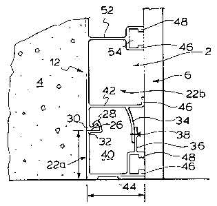
Figures 4 through 11 show additional details of the
panel sections and the cooperation therebetween. Figure 4
shows a standard 350 mm panel preferably of aluminum
comprising a left end panel section 22a, an intermediate
- 4 -
WH-9082/CA 2 1 4 I 4 6 3
panel section 22b, and a right end panel section 22c. The
panel sections are joined at panel junctions, generally
shown as 24. Adjacent the panel junctions, the panel
sections cooperate to foxm a box-like cell 40, which serves
to maintain the particular panel connection. The actual -
connection includes a hook 26 which is received within a
slot 28 of an adjacent panel section. These panel sections
have abutting shoulders 30 and 32 which form a tight
continuous joint. Overlapping flanges 34 and 36 are secured
in the final position by a rivet or screw 38. With this -
mechanical securement, the box-like cell 40 is complete and
will oppose forces exerted on the concrete wallform section -
and particularly forces exerted on the hook and slot
arrangement. It can further be appreciated that the load
exerted by the concrete will try to bow the concrete
engaging face Z2 inwardly and this is opposed by the box-
like cell 40, which acts as a column. This concrete load -
further increases the load maintaining abutment of shoulders
30 and 32. This produces a very shallow seam which does not
significantly imprint the concrete. The rigidity of the
system is accomplished using thin walled extrusions which
cooperate to form the box-like cells having high load
capability.
The overlapping flanges 3-4 and 36 are spaced
rearwardly of the concrete engaging face 12 by means of webs
42 and 44. Web 44 can include bolt slot 49 at the rear
surface thereof and also includes faces 46 and 48 which are
at the same distance as flange 46 on web 42. This results
in the wallform section having a number of rear support
surfaces 46, 48 which engage the strongback member. The
wallform section has a reinforcing rib adjacent a box-like
cell adjacent a reinforcing rib, adjacent a box-like cell,
etc. This provides high strength. A number of these
standard wallform sections, such as that shown in Figure 4,
may be assembled and disassembled and have a continuous
connection at the hook and slot junction. The individual
panels are maintained in their assembled condition, i.e. the
- 5 -
WH-9082/CA 2 1 4 1 4 6 3
screws 38 are maintained and the hook and slot arrangement
are maintained in engagement. The wallform sections may be
brought into engagement and cooperate with other wallform
sections by means of the mechanical clamping arrangement 62,
generally shown in Figure 5. As can be see, both the left
end panel section and right end panel section include end to
end panel section connections 60 which are engaged by the
mechanical clamp connector 62. Note that this clamp
provides high compressive loads at the planar surface and
can be vertically spaced as required.
The individual wallform sections are normally
aligned at the bottom edge, but this need not be the case.
For example, the sections could be shifted and secured to
collectively define a slope. This is a further advantage of
the hook and slot which can slide within each other as well
as the clamp which merely grasps the edges of adjacent
wallforms and does not rely on punched holes in the frame
flanges. No fabrication of the unit panel itself is
required prior to assembly and this results in low
manufacturing costs. It should also be recognized that the
panels do not need to be vertically oriented as shown. For
example, the panels can be oriented horizontally or at other
angles.
To add flexibility and to meet certain needs in the
marketplace, additional wallform sections of greater expanse
can be assembled and maintained. A 550 mm wallform section,
as shown in Figure 6, and a 750 mm panel section is shown in
Figure 7. These panel sections include additional
intermediate panels 22b which can ganged together. In
addition to the left end panel section, right end panel
section, there can be inside corner panel sections and
outside panel sections. In this way, various panels can be
assembled by means of this simple panel connection clamp 62
to form a camplete wall form. Once the job is complete, the
mechanical clamp 62 can be removed, the strongbacks removed,
etc. and the system broken down into the wallform sections
such as that shown in Figures 4, 6 and 7.
- 6 -
WH-9082/CA
2141463
The concrete wallform system utilizes a number of
standard components for building wallform sections a~
different widths. In this way, the manufacturing is
simplified (smaller extruded components, less warpage) and
greater flexibility in repair, assembly and salvage in the
field is possible. For example, if an intermediate panel is
damaged in the field, the wallform section may be repaired
by removing the damaged section and reassembling, if
desired, or by replacing the damaged section. Furthermore,
any damaged panels can be recycled as opposed to recycling
the entire wallform section. Any warpage in panel sections
is reduced when panel sections are assembled into a wallform
section. Warpage between abutting wallform sections is
reduced by the clamp arrangement, which aligns and
compresses at a position very close to the imprinting
surface. Several clamp arrangements can be used to meet the
load requirements and to provide reduce the visibility of
joints in the final product.
Figures 8, 9, 10 and 11 show details of the
mechanical connection of individual panels in the forming of
a wallform section. In Figure 8, two intermediate wallform
section panels are shown at a bent or angled configuration
to allow the hook 26 to be inserted in the slot arrangement
28 with generous clearance to facilitate assembly and
accommodate manufacturing tolerances (straightness) and
minimize damage related to use. As can be see, the overlap
and flanges are spaced from each other in this bent or
angled configuration (see Figure 8 and Figure 11). Once the
hook has been inserted in the slot arrangement, the panel
sections may then be rotated into a generally planar or
assembled condition as shown in Figures 9 and 10. To
maintain this assembled condition, a rivet or screw 38 can
pass through each of the overlapping flanges 34 and 36.
Other arrangements for maintaining the flanges can be used.
This assembly is convenient as the mechanical fastening
position is easily accessible due to its significant spacing
from the concrete imprinting face.
WH-9082/CA
2141463
As can be seen, the hook and slot arrangement and
the clearance of the flanges allows a very simple mechanical
connection, i.e. rivet or screw 38 to maintain the extruded
sections in the desired form. The abutting shoulders 30 and
32 maintain a tight continuous joint between panel sections
and therefore, use of the form does not contaminate the
connection. It can also be seen that the present invention
allows for various intermediate panels to be ganged together
to form wallform sections of greater width as desired. This
arrangement is also adaptable for a repair in the field in a
very simple manner. The mechanical connection 38 may be
removed and the panels sections disassembled. This may be
important if one becomes damaged or is desired to make up a
longer concrete wallform section.
This design and in particular the mechanical section
between panels sections overcomes certain difficulties known
with extrusion manufacture, i.e. there can be slight twists
etc. due to the extrusion process. The mechanical
connection allows insertion even if there is somewhat of a
twist of the hook and slot arrangement and the panels can
then be forced into the finished position merely by
completing the assembly operation eliminating the effect of
the twist.
It has been found with this structure that the panel
section can be relatively thin making it relatively low cost
yet the structure has good stiffness. This is of advantage
in that it simplifies the extrusion manufacturing process
and also reduces cost due to the lower material
requirements. The mechanical connection produces a tight
face at the concrete engaging surface assembles fast and has
an initial sloppy fit which eventually adjusts itself into
the final tight continuous fit. The joint transmits shear
in both directions and tends to stay together. It can also
be seen that the concrete wallform sections are partially
nestable in an offset manner and can be of a length of up to
about 3 meters.
_ g _
Wx-9oe2,~A 21414 63
s
It can further be appreciated that if desired, the
design can accommodate pre-stressing of the panels to
produce somewhat of an outwardly bowed concrete face -_
initially, which under concrete load will flatten out to the
desired surface and further strengthen the joint. As shown
in the diagrams, the wall sections used in this extrusion
are of about 2 mm. A further advantage of this system is
the fact that the wall form section is generally open at the
back and allows partial nesting or insertion of one wallform
section in the other in an opposed manner.
The clamp or panel connector 62 is made of a first
extruded component 64 and a second extruded component 66.
Component 66 includes two projecting flanges 68 which form a
slot for restricting rotation of nut 70. The bolt 72 passes
through ports in components 64 and 66 and engages nut 70.
The components have a hinge connection 74 therebetween and
opposed jaws 76 for clamping end to end panel connection 60
of adjacent abutting wall sections.
The clamp can be tightened or loosened by turning
bolt 72 appropriately with a spanner or socket and ratchet.
The adjustment is very accessible and convenient. The
design which allows components 64 and 66 to be extruded also
allows the height of the clamp, and thus, allows the
gripping effect thereof to be selected for the desired
effect and is cost effective to manufacture. The clamp also
maintains its assembly when loosened and is easy to place on
components 60 and draw the same into alignment. Clamps can
also be placed wherever required and the position is not -
fixed at discrete positions by the wallform sections.
The box-like cell cooperation is also used at
corners where two box cells cooperate to provide high
strength at positions normally under high load.
Although preferred embodiments of the invention have
been described herein in detail, it will be understood by
those skilled in the art, that variations may be made
thereto without departing from the spirit of the invention
or the scope of the appended claims.
_ g -