Language selection

Search

Patent 2141846 Summary

Third-party information liability

Some of the information on this Web page has been provided by external sources. The Government of Canada is not responsible for the accuracy, reliability or currency of the information supplied by external sources. Users wishing to rely upon this information should consult directly with the source of the information. Content provided by external sources is not subject to official languages, privacy and accessibility requirements.

Claims and Abstract availability

Any discrepancies in the text and image of the Claims and Abstract are due to differing posting times. Text of the Claims and Abstract are posted:

  • At the time the application is open to public inspection;
  • At the time of issue of the patent (grant).
(12) Patent Application: (11) CA 2141846
(54) English Title: PROCESS FOR CLEANING THE FILTER MODULES OF A PLANT FOR PURIFYING LIQUIDS
(54) French Title: PROCEDE POUR LE NETTOYAGE DE FILTRES MODULAIRES UTILISES DANS UNE INSTALLATION D'EPURATION DE LIQUIDES
Status: Deemed Abandoned and Beyond the Period of Reinstatement - Pending Response to Notice of Disregarded Communication
Bibliographic Data
(51) International Patent Classification (IPC):
  • B01D 65/02 (2006.01)
  • B01D 61/14 (2006.01)
  • B01D 65/08 (2006.01)
(72) Inventors :
  • HARTMANN, EDUARD (Switzerland)
(73) Owners :
  • BUCHER-GUYER AG MASCHINENFABRIK
(71) Applicants :
  • BUCHER-GUYER AG MASCHINENFABRIK (Switzerland)
(74) Agent: OSLER, HOSKIN & HARCOURT LLP
(74) Associate agent:
(45) Issued:
(86) PCT Filing Date: 1994-06-02
(87) Open to Public Inspection: 1994-12-22
Availability of licence: N/A
Dedicated to the Public: N/A
(25) Language of filing: English

Patent Cooperation Treaty (PCT): Yes
(86) PCT Filing Number: PCT/CH1994/000103
(87) International Publication Number: WO 1994029007
(85) National Entry: 1995-02-06

(30) Application Priority Data:
Application No. Country/Territory Date
1758/93-4 (Switzerland) 1993-06-11

Abstracts

English Abstract


ABSTRACT
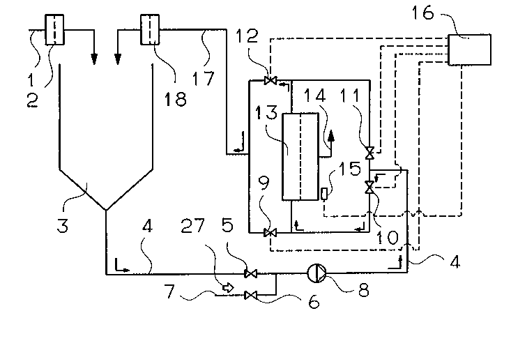
The process for cleaning the filtration modules (13)
of a cross-current filtration apparatus is carried out in a
system which is employed to clarify liquids, particularly
those with a high proportion of fiber. A problem in this
respect is the continuous accumulation of fibers, especially
at the entry to the filtration modules (13) at the face ends
of the various conduits, which can cause plugging. To
reduce the accumulations of fiber, when cleaning is done the
flow direction in the module (13) is reversed, compared with
the preceding filtration cycle. This is done by suitably
switching valves (9-12). Because of the reversal of the
flow direction flow cleaning, the fiber accumulations can be
easily detached while still small and flushed out of the
modules. Plugging up of the modules can thus be averted.


French Abstract

Le procédé de nettoyage des modules de filtration (11) d'un dispositif de filtration à courant transversal est exécuté dans une installation servant à la décantation de liquides, en particulier ceux contenant une proportion élevée de fibres. L'accumulation continue de fibres pose des problèmes en pareil cas, principalement à l'entrée des modules de filtration (13) placés aux extrémités avant des canaux, accumulation qui peut conduire à des obturations. Pour détruire les accumulations de fibres, on inverse, pendant le nettoyage, le sens de l'écoulement dans le module (13) par rapport au cycle de filtration précédent. Cette action est opérée par l'enclenchement des vannes (9 à 12). L'inversion du sens d'écoulement pendant le nettoyage permet de dissoudre facilement les accumulations de fibres demeurées peu importantes et de les évacuer à l'extérieur des modules. On peut ainsi éviter l'obturation de ces modules.

Claims

Note: Claims are shown in the official language in which they were submitted.

CLAIMS:
1. A process for cleaning the filtration modules in
a system for clarifying liquids with a high proportion of
fibers, particularly when micro- or ultrafiltration is
employed, characterized in that the flow direction in the
module (13) is reversible.
2. The process of claim 1, characterized in that the
flow direction in the module 13 is reversed prior to the
cleaning cycle.
3. The process of claim 1, characterized in that the
flow direction in the module (13) is reversed prior to the
ensuing filtration cycle.
4. The process of claim 1, characterized in that the
flow direction in the module (13) is reversed prior to both
the washing and the filtration cycles.
5. The process of one of claims 1-4, characterized in
that an actuation of valves (9, 10, 11, 12) which are
required for the reversal of the flow direction is effected
mechanically, electrically, pneumatically or hydraulically.
6. The process of one of claims 1-5, characterized in
that the triggering of the valves (9, 10, 11, 12) required
for the reversal of the flow direction is effected by hand
or via a control means (16).
7. The process of one of claims 1-6, characterized in
that the degree of contamination by the buildup of deposits
at the entry to the filtration elements is monitored by
sensors (15), and the cleaning operation is initiated
automatically once a defined contamination limit value is
reached.
- 4 -

8. The process of one of claims 1-7, characterized in
that the liquid to be clarified, after having passed through
the filtration modules (13), is additionally clarified
through a filter (18).
- 5 -

Description

Note: Descriptions are shown in the official language in which they were submitted.


~ . :
-` 214184~
P~OCESS FOR CLEANING l~IE FILTRATION
MOD~JLESIN A SYSTEM FOR CI.ARIFYING LIQUIDS
The invention relates to a process for cleaning the
filtration modules in a system for clarifying liquids,
particularly using microfiltration or ultrafiltration. The
invention offers advantages above all when cleaning is
carried out after the filtration of products that have a
high proportion of fiber, such as raw fruit or vegetable
juices or juices from other plant products.
In the clarification of liquids with a high proportion
of fiber, it is known that fibers collect preferentially at
the entry of the filtration modules at the face ends of the
various conduits and can cause them to stop up. Moreover,
the importation of fibers into the filtration system cannot
be entirely avoided even by prefiltering the product to be
clarified. The plugging up occurs either because the fiber
deposits, which increase during operation, continuously
decrease the cross section of the various conduits, or
layers of fiber that come detached are flushed into the
conduits and stick there. This latter phenomenon occurs
frequently in the conventional cleaning of filtration
modules as well.
In conventional cleaning of the filtration modules, it
i8 known, after a product has been positively displaced, to
carry out a multi-stage cleaning in the retentate loop. A
cleaning solution flows through the filtration modules,
followed by flushing with water. The flow direction in the
cleaning is the same as the working direction of the
filtration system. By itself, this known provision for
cleaning is inadequate to overcome the danger of plugging up
from fiber accumulations; on the contrary, as already noted,
this provision itself can cause plugging. The only,
quite expensive, possibility of averting plugging up from
fiber accumulation is to remove the armatures from the
modules at certain time intervals and to mechanically clean
them in the entry region.
It is therefore the object of the invention to create
a cleaning process for the systems referred to at the outset
.. : ~. . ,: . ,, .. , . . ....... :

21~18~
that assures disruption-free operation by means of periodic
removal of the fiber deposits.
According to the invention, this object is attained in
that in a periodic cleaning, the cleaning medium flows
through the filtration modules in the opposite direction
from the direction of filtration operation. In contrast to
the known standard cleaning process, the fiber accumulations
located at the entry of the modules are thus detached and
flushed out of the modules. Because of the periodic
cleaning, the fiber accumulations that come detached are so
small that they cannot lead to plugging up of the modules.
Further characteristics and advantageous features of
the invention are recited in the claims.
The invention is described in further detail in the
ensuing description and in the drawing, which schematically
illustrates one exemplary embodiment.
The drawing schematically shows a semicontinuous
cross-flow filtration apparatus, preferably including a
micro- or ultrafiltration device. However, the process
according to the invention may also be employed with a
single- or multi-stage continuously operated system.
The product to be clarified is supplied to a batch
tank 3, via a line 1 and a prefilter 2. A recirculating
pump 8 pumps the product to be clarified out of the batch
tank 3 into a retentate loop 4, in which a filtration module
13 is disposed. After leaving the filtration module 13, the
retentate flows back into the batch tank 3, via a line 17
and a filter 18. The permeate is drained off via a line 14.
Despite the use of the prefilter 2, fibers get into
the filtration system. Above all, they accumulate at the
entry to the filtration module, at the face ends of
individual conduits disposed in it. Because of the process
according to the invention, when cleaning is done to
eliminate these deposits, the flow direction of the flowing
medium in the filtration module 13 can be reversed. This is
done by changing the valve positions of the valves 9-12. To
reverse the flow direction shown in the drawi~ng, the valves
- 2 -
~"
, . ~ , -. :. -
. . .

~-` 21~18~
10 and 12 are closed and the valves 9 and 11 are opened.
The actuation of the valves may be effected mechanically,
electrically, hydraulically, or pneumatically. In the
present example, a control means 16 is provided for
triggering the valves, but other versions with manual
control are also possible. The initiation of the cleaning
process can be effected either perio'dically or as a function
of the state of contamination ascertained by a sensor 15.
The switchover of the flow direction is effected prior ~-
to the cleaning, after the end of the filtration cycle and
an ensuing positive displacement of the product. As
indicated by the arrow 27, water is pumped in this process
out of an inflow line 7 into the retentate loop 4 by the
recirculating pump 8, as a result of the closure of a valve
5 and the opening of a valve 6. The retentate remaining in
the line system after the end of the filtration cycle is
positively displaced into the batch tank 3 in this process.
After the end of the cleaning cycle, the flow
direction for the ensuing filtration cycle can either be
changed back into that of the prior filtration cycle or left
unchanged. If the flow direction is left unchanged after
cleaning, then the advantage is that by changing the flow
direction for the filtration cycles, the strain on the
modules is more uniform (making for a longer service life).
. ,. ,~.. . ... .
- 3 - - ~

Representative Drawing
A single figure which represents the drawing illustrating the invention.
Administrative Status

2024-08-01:As part of the Next Generation Patents (NGP) transition, the Canadian Patents Database (CPD) now contains a more detailed Event History, which replicates the Event Log of our new back-office solution.

Please note that "Inactive:" events refers to events no longer in use in our new back-office solution.

For a clearer understanding of the status of the application/patent presented on this page, the site Disclaimer , as well as the definitions for Patent , Event History , Maintenance Fee  and Payment History  should be consulted.

Event History

Description Date
Time Limit for Reversal Expired 1997-06-02
Application Not Reinstated by Deadline 1997-06-02
Deemed Abandoned - Failure to Respond to Maintenance Fee Notice 1996-06-03
Application Published (Open to Public Inspection) 1994-12-22

Abandonment History

Abandonment Date Reason Reinstatement Date
1996-06-03
Owners on Record

Note: Records showing the ownership history in alphabetical order.

Current Owners on Record
BUCHER-GUYER AG MASCHINENFABRIK
Past Owners on Record
EDUARD HARTMANN
Past Owners that do not appear in the "Owners on Record" listing will appear in other documentation within the application.
Documents

To view selected files, please enter reCAPTCHA code :


To view images, click a link in the Document Description column. To download the documents, select one or more checkboxes in the first column and then click the "Download Selected in PDF format (Zip Archive)" or the "Download Selected as Single PDF" button.

List of published and non-published patent-specific documents on the CPD .

If you have any difficulty accessing content, you can call the Client Service Centre at 1-866-997-1936 or send them an e-mail at CIPO Client Service Centre.


Document
Description 
Date
(yyyy-mm-dd) 
Number of pages   Size of Image (KB) 
Claims 1994-12-22 2 60
Cover Page 1994-12-22 1 31
Drawings 1994-12-22 1 17
Abstract 1994-12-22 1 34
Descriptions 1994-12-22 3 158
Representative drawing 1999-06-15 1 14
International preliminary examination report 1995-02-06 13 474
Courtesy - Office Letter 1995-08-01 1 39