Language selection

Search

Patent 2142059 Summary

Third-party information liability

Some of the information on this Web page has been provided by external sources. The Government of Canada is not responsible for the accuracy, reliability or currency of the information supplied by external sources. Users wishing to rely upon this information should consult directly with the source of the information. Content provided by external sources is not subject to official languages, privacy and accessibility requirements.

Claims and Abstract availability

Any discrepancies in the text and image of the Claims and Abstract are due to differing posting times. Text of the Claims and Abstract are posted:

  • At the time the application is open to public inspection;
  • At the time of issue of the patent (grant).
(12) Patent Application: (11) CA 2142059
(54) English Title: WINDOW SHADE WITH BREAK-AWAY ATTACHMENT OF LIFT CORDS TO BOTTOM RAIL
(54) French Title: STORE POUR FENETRE AVEC DISPOSITIF DE SECURITE POUR LES ENFANTS
Status: Deemed Abandoned and Beyond the Period of Reinstatement - Pending Response to Notice of Disregarded Communication
Bibliographic Data
(51) International Patent Classification (IPC):
  • E06B 9/322 (2006.01)
  • E06B 9/262 (2006.01)
  • E06B 9/326 (2006.01)
(72) Inventors :
  • GENOVA, JOHN R. (United States of America)
(73) Owners :
  • SPRINGS WINDOW FASHIONS DIVISION, INC.
(71) Applicants :
  • SPRINGS WINDOW FASHIONS DIVISION, INC. (United States of America)
(74) Agent: SMART & BIGGAR LP
(74) Associate agent:
(45) Issued:
(22) Filed Date: 1995-02-08
(41) Open to Public Inspection: 1995-10-01
Availability of licence: N/A
Dedicated to the Public: N/A
(25) Language of filing: English

Patent Cooperation Treaty (PCT): No

(30) Application Priority Data:
Application No. Country/Territory Date
08/220,663 (United States of America) 1994-03-31

Abstracts

English Abstract


A window shade assembly comprising a header, a bottom
rail and expansible and contractable shade means attached
to the header and bottom rail, and lift cords attached to
the bottom rail and extending upwardly to the header and
through a cord lock on the header and having lift cord
operating portions extending downwardly from the cord lock
means for raising and lowering the bottom rail, the lower
ends of the operating portions of the lift cords are
detachably mounted on the bottom rail to be raised and
lowered with the bottom rail to reduce cord dangle and the
detachable mounting is arranged to allow the lower end of
the operating portion of each lift cord to detach from the
bottom rail and separate from the operating portions of
the other lift cords when the lower end of the lift cord
is subjected to a tensile force in a direction away from
the bottom rail, for child safety reasons.


Claims

Note: Claims are shown in the official language in which they were submitted.

The embodiments of the invention in which an exclu-
sive property or privilege is claimed are defined as
follows:
1. A window shade assembly comprising a header, a
bottom rail and expansible and contractable shade means
attached to the header and bottom rail, bottom rail oper-
ating means including at least two lift cords attached to
the bottom rail and extending upwardly to the header and
through cord lock means on the header, the bottom rail
operating means including at least one operating portion
extending downwardly from the cord lock means and manually
operable for moving the bottom rail between upper and
lower positions, the operating portion having a length
sufficient to extend below the lower rail when the latter
is in said lower position thereof, a cord end member on a
lower end of the operation portion, and means detachably
mounting the cord end member on the bottom rail, the
detachable mounting means being constructed and arranged
to allow the cord end member to detach from the mounting
means on the bottom rail when the associated operating
portion is subjected to a tensile force in a direction
away from the bottom rail.
2. A window shade assembly comprising a header, a
bottom rail and expansible and contractable shade means
attached to the header and bottom rail, at least two lift
cords attached to the bottom rail and extending upwardly
to the header and through cord lock means on the header
and having depending portions extending downwardly from
the cord lock means and manually operable to move the
bottom rail between upper and lower positions, the depend-
ent portions having a length sufficient to extend below

the bottom rail when the latter is in said lower position
thereof, and means detachably mounting lower ends of the
depending portions of the lift cords on the bottom rail to
be raised and lowered with the bottom rail, the detachable
mounting means being constructed and arranged to allow the
lower end of the depending portion of each lift cord to
detach from the bottom rail and separate from the depend-
ing portions of the other lift cords when the lower end of
the lift cord is subjected to a tensile force in a direc-
tion away from the bottom rail.
3. A window shade assembly comprising a header, a
bottom rail and expansible and contractable shade means
attached to the header and bottom rail, at least two lift
cords attached to the bottom rail and extending upwardly
to the header and through cord lock means on the header
and having operating end portions extending downwardly
from the cord lock means and manually operable to move the
bottom rail between upper and lower positions, the lift
cords having a length sufficient to extend below the
bottom rail when the latter is in said lower position
thereof, a cord end member on a lower end of the operating
portions of each lift cord, and means detachably mounting
the cord end members on the bottom rail, the detachable
mounting means being constructed and arranged to allow the
cord end members to individually detach from the mounting
means on the bottom rail and separate from the other
connector members when the associated operating portion is
subjected to a tensile force in a direction away from the
mounting means on the bottom rail.
4. A window shade assembly according to claim 3
wherein the mounting means has a plurality of sockets and
each cord end member is arranged for releasable reception
in a socket.

8
5. A window shade assembly according to claim 4
wherein the sockets each open in a generally downwardly
facing direction.

Description

Note: Descriptions are shown in the official language in which they were submitted.


2142059
5 - ~INDOW 8HADE WITH BREAK-AWAY ATTACHMENT
OF ~IFT CORD8 TO BOTTOM RAI~
BAC~GROUND OF THE INVENTION
The present invention relates to window shades of the
type in which lift cords are attached to the bottom rail
and extend upwardly to a header and through a cord lock on
the header with operating portions extending downwardly
from the cord lock. The operating portions are manually
pulled downwardly to raise the bottom rail and, when the
bottom rail is fully raised, the operating portion of the
lift cords will frequently extend below the window sill
and even adjacent to or onto the floor. The low dangling
cords not only present an untidy appearance, but also
present a potential hazard to children who sometimes play
with and become entangled with the cords.
U.S. Patent 3,485,285 discloses a blind construction
in which the operating portion of the lift cords is in the
form of a loop and the lower end of the loop is attached
to the bottom rail to be raised and lowered with the
bottom rail. Since the lower end of the operating cord
loop moves upwardly as the bottom rail is raised, this
arrangement effectively overcomes the problem of dangling
of the lift cord on or adjacent the floor when the bottom
3~ rail is raised. However, the operating cords when at-
tached to the bottom rail, form a loop which could consti-
tute a noose if a child places his head in the loop.
Further, since the operating cords are connected into a

21420S9
continuous loop at their lower ends, the danger also
exists that a child could be injured by placing his head
between the interconnected operating cords.
U. S. Patent 4,909,298 discloses a cord pull for
detachably interconnecting the lower ends of the operating
portions of the venetian blind lift cords. This is in-
tended to allow the lower ends of the lift cords to sepa-
rate when a force is applied to the cord pull at a loca-
tion between the cords. In order to position the other-
wise dangling ends of the cords at a safe vertical dis-
tance above the floor, this patent suggests wrapping the
cords around the cord pull members and attaching the cord
pull members to the headrail or to an upper portion of the
window frame. However, this requires a special manual
operation after the shade is raised in order to store the
dangling ends of the lift cords, and a further manual
operation to reverse the storage of the lift cords prior
to lowering of the shade.
BRIEF DESCRIPTION OF THE DRAWINGS
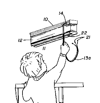
FIGURE 1 is a perspective view of a window shade
embodying the invention showing the lift cords when the
window shade is in a lowered position;
Fig. 2 is a fragmentary perspective view illustrating
the lift cords when the window shade is raised;
Fig. 3 is a fragmentary perspective view illustrating
the detachment of the lift cords from the bottom rail; and
Fig. 4 is a fragmentary sectional view through the
means for mounting the ends of the lift cord on the bottom
rail.

21~2059
DETATT~n DESCRIPTION
The present invention relates to window shades of the
type having a header 10, a bottom rail 11 and expansible
and contractable shade means 12 attached to and extending
between the header and the bottom rail. The expansible
and collapsible shade means 12 can be of folded or cellu-
lar material or of the venetian blind type in which slats
are supported on ladder tapes. The bottom rail is adapted
to be raised and lowered by lift cords 13 that are at-
tached at one end to the bottom rail 11 and extend upward-
ly through the shade and into the header 10 and exit from
a cord lock 14 on the header. The lift cords have operat-
ing portions 13a that extend downwardly from the headrail
and which are operative, when pulled downwardly, to raise
the bottom rail from the fully lowered position as shown
in Fig. 1 to a raised position as shown in Figs. 2 and 3.
As is conventional, the cord lock 14 is arranged to lock
the lift cords against movement in different vertically
adjusted positions of the bottom rail between the fully
lowered position and the fully raised position and the
cord lock means is operated between its lock and release
conditions in response to lateral shifting of the operat-
ing portion of the lift cord. A cord equalizer 15, for
example of the type shown in U. S. Patent 5,058,650, is
commonly provided on the lift cords to equalize movement
of the lift cords and maintain the bottom rail generally
horizontal during raising and lowering of the shade.
In accordance with the present invention, means are
provided for detachably mounting the lower ends of the
lift cord operating portion on the bottom rail so that the
lower ends of the lift cord normally move with the bottom
rail. Thus, when the operating portions 13a are pulled

2142059
downwardly, the bottom rail 11 is raised and the lower
ends of the upper end portions are drawn upwardly to limit
downward dangle of the lift cords. The attachable mount-
ing means is constructed and arranged to allow the lower
ends of the lift cord operating portions to detach from
the bottom rail and separate from the depending portions
of other lift cords, when the lower end of the lift cord
is subjected to a tensile force in a direction away from
the bottom rail. The operating portion of the lift cords
between the headrail and bottom rail forms a slack loop as
shown in Figs. 1 and 2. However, if a child is caught in
a loop formed by one or more or all of the lift cords, the
lift cords can individually detach from the bottom rail
and thus break up not only the loop formed by attaching
the ends of the lift cords to the bottom rail, but also
the loop or loops formed between adjacent ones of the lift
cords.
In the preferred embodiment illustrated, cord end
members 21 are molded or crimped onto the lower end of
each lift cord operating portion and a mounting member 22
is provided with a plurality of sockets 23, at least equal
in number to cords in the lift cord operating portion 13a.
The mounting portion is preferably formed of a resilient
plastic material to facilitate detachment and reinstalla-
tion of the lift cord end members. In the embodimentillustrated, the mounting member 22 is formed with a
collar 25 adapted to be inserted through an opening in the
bottom rail and which is shaped to normally retain the
mounting member on the bottom rail. It is also contem-
plated that the mount~ng member 22 could be formed as apart of an end cap such as shown at lla on the bottom
rail. In order to facilitate detachment of the cord end
members 21 from the mounting member 22, the sockets 23 on

2142059
the mounting member are preferably each arranged to open
in a generally downwardly facing direction so that a
relatively low downward tension on a lift cord will pull
the associated lift cord end member out of the socket in
the mounting member 22 to minimize the likelihood of a
child being strangled if it gets its head in a cord loop.
From the foregoing it is believed that the operation
and construction of the window shade assembly will be
readily understood. Attachment of the lower ends of the
lift cord operating portion, raises the lower ends of the
lift cord operating portion as the window shade is raised
so that the vertical height of the loop formed in the cord
operating portions remains substantially constant. This
reduces the likelihood that a child on the floor would be
able to reach the operating cords. Further, the detach-
able mounting of the lower ends of the lift cord operating
portions on the bottom rail allows the lift cord end
members to individually detach from the bottom rail and to
separate from each other so as to not only break up the
loop in the operating cord formed between the header and
bottom rail, but also the loops formed between adjacent
ones of the lift cord operating portions.

Representative Drawing
A single figure which represents the drawing illustrating the invention.
Administrative Status

2024-08-01:As part of the Next Generation Patents (NGP) transition, the Canadian Patents Database (CPD) now contains a more detailed Event History, which replicates the Event Log of our new back-office solution.

Please note that "Inactive:" events refers to events no longer in use in our new back-office solution.

For a clearer understanding of the status of the application/patent presented on this page, the site Disclaimer , as well as the definitions for Patent , Event History , Maintenance Fee  and Payment History  should be consulted.

Event History

Description Date
Inactive: IPC from MCD 2006-03-11
Time Limit for Reversal Expired 1999-02-08
Application Not Reinstated by Deadline 1999-02-08
Deemed Abandoned - Failure to Respond to Maintenance Fee Notice 1998-02-09
Letter Sent 1997-06-18
Reinstatement Requirements Deemed Compliant for All Abandonment Reasons 1997-06-09
Inactive: Adhoc Request Documented 1997-02-10
Deemed Abandoned - Failure to Respond to Maintenance Fee Notice 1997-02-10
Application Published (Open to Public Inspection) 1995-10-01

Abandonment History

Abandonment Date Reason Reinstatement Date
1998-02-09
1997-02-10

Maintenance Fee

The last payment was received on 1997-06-09

Note : If the full payment has not been received on or before the date indicated, a further fee may be required which may be one of the following

  • the reinstatement fee;
  • the late payment fee; or
  • additional fee to reverse deemed expiry.

Please refer to the CIPO Patent Fees web page to see all current fee amounts.

Fee History

Fee Type Anniversary Year Due Date Paid Date
Reinstatement 1997-06-09
MF (application, 2nd anniv.) - standard 02 1997-02-10 1997-06-09
Owners on Record

Note: Records showing the ownership history in alphabetical order.

Current Owners on Record
SPRINGS WINDOW FASHIONS DIVISION, INC.
Past Owners on Record
JOHN R. GENOVA
Past Owners that do not appear in the "Owners on Record" listing will appear in other documentation within the application.
Documents

To view selected files, please enter reCAPTCHA code :


To view images, click a link in the Document Description column. To download the documents, select one or more checkboxes in the first column and then click the "Download Selected in PDF format (Zip Archive)" or the "Download Selected as Single PDF" button.

List of published and non-published patent-specific documents on the CPD .

If you have any difficulty accessing content, you can call the Client Service Centre at 1-866-997-1936 or send them an e-mail at CIPO Client Service Centre.


Document
Description 
Date
(yyyy-mm-dd) 
Number of pages   Size of Image (KB) 
Cover Page 1995-11-21 1 16
Abstract 1995-10-01 1 25
Description 1995-10-01 5 205
Claims 1995-10-01 3 99
Drawings 1995-10-01 1 48
Representative drawing 1998-03-13 1 10
Notice of Reinstatement 1997-06-18 1 162
Courtesy - Abandonment Letter (Maintenance Fee) 1998-03-09 1 187
Fees 1997-06-09 1 38