Note: Descriptions are shown in the official language in which they were submitted.
,` 2142079
MFTHOD AND APPARATUg FOR TFSTING
~H~ SIDBWALLS OF CONTAIN~RS
The invention relates to a method according to the preamble
of Claim 1. Further, the invention relates to an apparatus for
accomplishing the method.
It is known to test the sidewalls of containers optically.
In particular, this is undertaken with recyclable containers
(e.g., recyclable bottle~ made of glass or plastic). Moreover,
the container is rotated 360 degrees in front of a slit shutter
camera so that the entire wall of the container is examined along
A~ 11~o
a line. From U.S. patent 4,750, 035 and British patent Gs-A-2,
165, 942 a method according to the preamble is known by which the
containers are rotated between the picture taking stations.
Since the testing of containers in the case of recyclable
bottles must take place in an industrial environment and at very
high speeds (today conveyor devices in filling plants are operated
with bottle processing rates of 30,000 to 60,000 bottles per
hour), it is an object on the one hand to make possible sidewall
testing which does not affect the container processing rate on the
conveyor device. On the other hand, the photograph should result
as much as possible in a form suitable for evaluation and at a
most favorable cost.
~ `` 21~207!~
. ~
This object is accomplished by a method of the above
mentioned type with the characterizing features of Claim 1.
Further, the object of providing a corresponding apparatus is
accomplished by means of an apparatus according to Claim 3.
Through the placement o~ multiple picture stations along a
conveyor path, each of which photographs only one sidewall
section, very rapid testing i8 provided. Moreover, all sidewall
sections are taken by one picture taking device which yields a
particularly cost-effective solution; the multiple reflections
produce a long beam path, an advantageous consideration for the
evaluation.
Preferred embodiments of the invention are further described
below with the aid of drawings in which;
Fig. 1 is a schematic of one portion of a bottle conveying
apparatus for accomplishing the method;
Fig. 2 is a schematic of one portion of a further bottle
conveying apparatus for accomplishing the method;
Fig. 3 is a schematic picture of the bottle sidewall
sections;
Fig. 4 is a schematic of a further apparatus with a semi-
reflecting mirror and a camera;
Fig. 5 is likewise a schematic of an apparatus with a semi-
reflecting mirror and camera
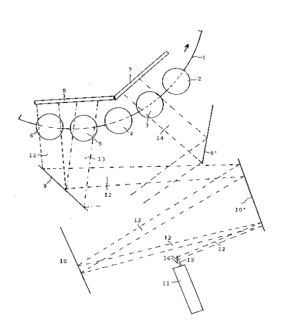
Fig. 1 illustrates generally schematically a portion of a
container conveying installation for transparent and containers,
in particular for recyclable PET bottles. The conveying
installation is comprised, moreover, of a carousel 1 for the
2142~79
; . ~
bottles which is only illustrated in part with the bottles 2, 3,
4, 5, and 6, and these are conveyed in the direction of the arrow.
On the whole carousel naturally more bottles are found and as a
rule, a series of testing stations are arranged on the carousel,
which stations, for example test for the presence of residual
liquids, dangerous substances, the condition of the bottom of the
bottle, and so forth.
Preferably, the entire sidewall of each bottle is tested on
an optical path. In Figure 1, illumination devices 7 and 8 are
provided for this purpose, and these devices illuminate each
section of the sidewall. Moreover, flashlamps or pulse-operated
~ED arrays are contemplated as illumination devices. Also, a
continuous illumination, likewise provided by lamps or lamp
diodes, is possible if the picture taking device is provided with
a shutter or a similar device which guarantees that a brief,
unblurred picture is taken of each of the moving bottles.
In the illustrated embodiment each sidewall section of a
bottle 2, 3, 5, and 6 is simultaneously photographed by video
camera 11. Moreover, in Fig. 1 only one beam path 12 from the
illumination device 8 to the bottle 6 and to the camera 11 is
shown completely. The beam paths for the other bottles are only
partially indicated (bottle 5 with the beam path 13, bottle 3 with
the beam path 14) or nothing is shown at all (bottle 2) in order
to keep the figure clear. The section of a sidewall of the bottle
6 to be photographed is accordingly illuminated by the
illumination device 8 and is reflected at the first mirror 9 to
the mirror 10' and from there to the mirror 10, again to the
2142079
mirror 10' and from there to the camera 11 by means of the mirror
arrangement 16. It is apparent that the simultaneously
photographed sidewall sections of the bottles 5, 3 and 2 are
projected to the camera 11 in a similar manner by means of the
mirrors 9, 9', 10, 10' and 16. The momentary picture received by
the camera, therefore, consists of four sidewall sections
simultaneously, one for each of the bottles 6, 5, 3 and 2, which
are projected to the camera by means of the two mirrored surfaces
of the V-shaped mirror 16.
The bottles are advanced further which accordingly results in
the bottle 6 assuming the same position at a later point in time
which the bottle 5 assumed in Fig. 1. Similarly, at this time,
bottle 5 of Fig. 1 is found in the same position that the bottle 4
occupied in Fig. 1. At this point in time another bottle which is
not visible in Fig. 1 iS pushed into the position of the bottle 6
in Fig. 1. The bottle 2 of Fig. 1 at this point in time i8 no
longer in the region of the sidewall testing. With the
advancement of the bottles in the region of sidewall testing the
bottles are rotated about their vertical axis. With the
advancement of the bottle 6 from the position in Fig. 1 to the
position at which the next picture photograph is taken (position
of the bottle 5 in Fig. 1) a rotation takes place in the
illustrated example such that a sidewall section of the bottle
shifted by 90 is photographed. Correspondingly, the other
bottles are also rotated and the next photographs by the camera 11
therefore again show four sidewall sections whereby in contrast to
the previous photograph of the bottles 6, 5, and 3, however, other
2142~79
. ~
sidewall sections are photographed since each of the bottles has
been rotated. The process is repeated continuously. With each
new photograph again four new sidewall sections are photographed
through the V-shaped mirror 16. In other words, for example, the
bottle 6 illustrated in Fig. 1 is photographed four times by the
camera 11 along the illustrated conveyor section whereby each time
a different sidewall section is photographed since the bottle 6
during a passage through the conveyor section rotates about its
own axis. Moreover, the photographs are produced in such a manner
that, as a rule, the sequentially photographed sidewall sections
of the same bottle overlap. The rotation of the bottle about its
axis can be affected by known drive elements which are not
illustrated in the figures. For this, one might consider a
rotational drive by means of a cam control located below the
carousel or a step motor drive.
Naturally, the picture path can also be realized in other
fashions than with the mirrors 9, 9', 10, 10' and 16 shown. It is
contemplated, however, to use the longest possible beam path
through multiple reflections so that an observation of the bottle
sidewalls through the camera 11 is as parallel as possible.
Further, it is preferred that the camera be arranged in the
vertical direction below the center of the bottle and in this
position it is directed upwardly toward the bottle. This allows a
good observation of the so-called ~wear bands~ of the bottle and
permits one to see over the bottle dome.
The eva~uation of the photographed pictures is produced in a
known manner through machine analysis of the pictures. Moreover,
'` ~ 214207g
naturally the correlation of each sidewall section with the
bottles must be guaranteed since each bottle appears in the four
pictures. The recognition of damage or contamination of a bottle
by means of the photographed pictures leads in a known manner to
the sorting of the corresponding bottles.
Fig. 2 shows a further embodiment with a conveying carousel
21 and six testing stations with illumination devices 32 to 37 for
which the above referenced operation is likewise valid. In this
example the sidewall sections of six bottles 23, 24, 25, and 28,
29, 30 are simultaneously photographed by one (or more) cameras
(not illustrated in Fig. 2). Moreover, the beam path, as
illustrated with the aid of bottles 24 and 30 extends between the
mirrors 38', 39' or correspondingly 38, 39. For the remaining
bottles only the beginning of the beam i8 indicated. In this
embodiment also the bottles are rotated along their feedpath by
means of drive elements 40 so that in each photo position a
different sidewall section is photographed. Accordingly, at the
8ix photo stations in Fig. 2 each bottle is rotated so that a
section of the bottle sidewall shifted by 60- is viewed. Between
the positions of the bottles 26, and 27 in Fig. 2 no rotation is
produced and correspondingly rotation is produced only between
the positions of the bottles 25 and 28 since in between, no photos
are taken. This is naturally also true for the corresponding
position of the bottle 4 in Fig. 1.
Fig. 3 shows schematically a picture 41 which reproduces each
of the sidewall sections of the bottles 23, 24, 25 and 28, 29, 30
corresponding to the momentary photographic situations of Fig. 2.
~ 2142~79
Another preferred type of illustration brings three sidewall
sections in adjacent positions (therefore, in contrast to the 90'
rotation of Fig. 3) onto the light receiving surface of the camera
for viewing. For this, in general the CCD-chip camera is quite
useful and produces a good result. Then, two such camera pictures
will be needed for each 60 degree observation of the bottle
sidewalls. The observation of the bottles in each of the six
sections, therefore each shifted by 60 , employing fewer sections,
has the advantage that no or ~;n~ m~ l edge loss of light is caused
and defects in the edge region are more easily recognized.
Fig. 4 shows schematically an arrangement for the
photographing of each of three sidewall sections in one picture.
Moreover, a semi-reflecting mirror 42 is positioned in the beam in
front of the camera 11. Therefore, it is possible to illuminate
the bottles 43, 44 and 45 at once and the photograph of the three
bottle sidewall sections is produced such that the light passes
through the mirror 42. Accordingly, the bottles 47, 48, 49 are
illuminated and the photograph of the three bottle sidewall
sections is produced through the reflection of light onto the
mirror 42.
Fig. 5 only shows the region of the camera for a further
apparatus which is otherwise like the apparatus of Fig. 4.
Moreover, two mirrors 50 and 51 and a semi-reflecting mirror 52
are provided. With a photograph of each of the three sidewall
sections by means of the camera 11 the beam path runs to the
camera in one case from the left by means of the mirror 50 and a
reflection at the mirror 52. In the other case, the beam path
21~!207~
runs to the camera by way of the mirror 51 and through the mirror
52 whereby in each case the mirror 53 reflects the beam onto the
camera axi~.
In the illustrated manners the sidewalls of containers can be
photographed with a camera at a high rate and good results which
allows rapid testing of the same.