Language selection

Search

Patent 2142442 Summary

Third-party information liability

Some of the information on this Web page has been provided by external sources. The Government of Canada is not responsible for the accuracy, reliability or currency of the information supplied by external sources. Users wishing to rely upon this information should consult directly with the source of the information. Content provided by external sources is not subject to official languages, privacy and accessibility requirements.

Claims and Abstract availability

Any discrepancies in the text and image of the Claims and Abstract are due to differing posting times. Text of the Claims and Abstract are posted:

  • At the time the application is open to public inspection;
  • At the time of issue of the patent (grant).
(12) Patent: (11) CA 2142442
(54) English Title: ADJUSTABLE SHELF FOR A REFRIGERATOR
(54) French Title: CLAYETTE REGLABLE POUR REFRIGERATEUR
Status: Expired and beyond the Period of Reversal
Bibliographic Data
(51) International Patent Classification (IPC):
  • F25D 25/02 (2006.01)
  • A47B 45/00 (2006.01)
  • A47F 05/13 (2006.01)
(72) Inventors :
  • TUNZI, TODD J. (United States of America)
(73) Owners :
  • MAYTAG CORPORATION
(71) Applicants :
  • MAYTAG CORPORATION (United States of America)
(74) Agent: FINLAYSON & SINGLEHURST
(74) Associate agent:
(45) Issued: 2002-05-28
(22) Filed Date: 1995-02-13
(41) Open to Public Inspection: 1996-07-18
Examination requested: 1998-12-11
Availability of licence: N/A
Dedicated to the Public: N/A
(25) Language of filing: English

Patent Cooperation Treaty (PCT): No

(30) Application Priority Data:
Application No. Country/Territory Date
08/373,383 (United States of America) 1995-01-17

Abstracts

English Abstract


An adjustable shelf for a refrigerator compartment has two parts, a platform
and a support member and provides adjustment of both the length and the height of
the shelf. The platform is attached at a first end to a compartment wall at one of two
heights. The support member is slidably attached to the second end of the platform
to allow adjustment of the length of the shelf. The support member has two legs with
different lengths. The selection of the leg to support the platform in cooperation with
selection of the corresponding attachment height at the first end of the platform
determines the height of the shelf.


Claims

Note: Claims are shown in the official language in which they were submitted.

The embodiments of the invention in which an exclusive property or privilege
is claimed are defined as follows:
1.
An adjustable shelf for an appliance comprising:
a platform selectably attachable at a first end to a wall of the appliance at a
first height and a second height;
an "L" shaped support member having a first leg and a second leg, the legs
being of different lengths and selectably attachable to the second end of the platform
to selectably extend a plurality of lengths beyond the second end of the platform;
and wherein when the first leg of the support member is attached to the second
end of the platform the second leg of the support member supports the platform at the
first height and when the second leg of the support member is attached to the second
end of the platform the first leg of the support member supports the platform at the
second height.
2.
The adjustable shelf of Claim 1 wherein:
the first and second legs of the support member are slidably attachable to the
platform to adjustably extend beyond the second end of the platform.
3.
The adjustable shelf of Claim 2 further comprising:
a first and second flange extending below the platform on each side of the
second end of the platform to define channels for slidably receiving one of the first
and second legs of the support member.

Description

Note: Descriptions are shown in the official language in which they were submitted.


~1424~2
AD~USTABLE SHELF FOR A REFRIGERATOR
BA(~KGROUNl~ OF THF. INVF.I~TION
The present irlvention relates to an adjustable shelf for a refrigerator. The
adjustable shelf is particularly useful in the freezer . ,..,.~ , but can also be used
5 in the fresh food cu~ JalL~
Previous shelving systems for I~L;~ aLu,~ have allowed only limited flexibility
in the AIIAII~ I of shelves. Users of l~irl;~d~UI~. often wish to store items that
ceed the maximum height allowed by the shelves. In such a case, users must either
remove a shelf or transfer the item to a package that will fit within the confines of the
space defined by the existing shelf. Some ~ir.;~ ,.v.~ in the past have been provided
with shelves that can be adjusted in length to provide a gap between the end of the
shelf and a wall of the ~.UIll~alLI~ , this gap provides a taller space within the
,.. 1 It is also known to provide alternative attachment points for a shelf at
varying heights to allow some vertical adjusttnent of the shelf. It has heretofore not
been possible, however, to provide a shelf that is adjustable both vertically and
horizontally, providing the consumer with maximum flexibility.
Therefore, it is an object of the present invention to provide a shelf for a
refrigerator that can be adjusted both vertically and ~- lly~
A further object of the present invention is to provide an adjustable shelf thatis easy to adjust and rearrange in ~iUllrl~Uld~iUII.
SUMMARY OF THE INVENTION
The foregoing objects are achieved by=an adjustable shelf for a ICII;y,~,latW
~ UIll~JalL~ ,l.. comprising a platform attachable at a first end to the ~ " .. ~ wall
at a first and a second height. An "L" shaped support member having one leg longer
than the other is attachable to the second end of the platform with one leg of the
support member extending beyond the platform to provide variation in the length of
the shelf and the other leg of the support member extending downward to provide
support for the second end of the platform. The attachment of the shelf at the f rst

2142q42
height at the first end and to the first leg of the support member at the second end
provides a first height of the platform and attachment of the shelf at the second height
at the first end and at~achment to the second leg of the support member at the second
end provides a second height of the platform.
s
BRIEP DESCR~PTION OF TE~E DRAWINGS
Figure 1 is a perspective view of a refrigerator il~....,l,..l,.llll~ the present
invention.
Figure 2 is an exploded view of an adjustable rack.
Figure 3 is an exploded view of an alternative adjustable rack.
Figure 4 is a perspective view of the alternative adjustable rack.
DETAILED DESCRIPTION QF THE PREFERRED EMBODIMENT
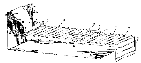
Referring to Figures 1 - 4, a refrigerator 10 is shown including a freezer
~,u~ a~ l 20 and a re~igerator l.:UIIIlJal~ .l. 22. An adjustable shelf 30 in
accordance Witl1 the current invention is shown in the freezer 20. The freezer 20
further comprises a first wall 40 and a second wall 50.
One of the walls 40 includes at least a first pair of receptacles 42 and a second
pair of receptacles 43. The pairs of receptacles 42,43 are spaced apart on the wall at
two different heights. A pair of holding brackets 44 each having a hook 45 on one
side and a centrally located screw hole 46 as best shown in Figure 2 is secured to one
of the receptacles of a pair 42,43 via a threaded screw 47. When attached, the hooks
45 are in substantial horizontal alignment in the freezer .~,l,,~--l,.,. .,l 20. The holding
brackets 44 could be attached wall 40 in a number of other ways including glue, tabs
or other suitable means.
The adjustable shelf 30 includes a platform 60 and an "L" shaped support
member 70. Both the platform 60 and support member ~0 are shown constructed of
coated wire although other materials such as molded plastic or other suitable material
may be used.

~142442
At a frst end, the platform 60 includes a wire 68 across the under side. This
wire 68 is formed to provide a snug fit with the hooks 45 and the holding brackets 44
mounted to the freezer first wall 40. The hooks 45, in cooperation with the wire 68
thus provide support for one end of the platform 60. A variety of altemative
supporting ~ may be used including flanges, pegs or other suitable means
irl place of the described holding brackets 44. On the under side of a second end, the
platform 60 includes a pair of flanges 62. The flanges 62 are on opposite sides of the
platfomm 60 and face each other . A channel 64 is deflned by the flanges 62.
The support member 70 is substantially "L" shaped with a frst leg 72 and a
second leg 74. The first leg 72 is shorter than the second leg 74. The support
member 70 is fommed to provide a snug fit when slidably inserted into the channel 64
of the platform 60.
In a first ~rrAn~,-.m, nt, the holding brackets 44 are inserted into the higher of
the pairs of receptacles 43 and the first leg 72 of the support member 70 is inserted
IS into the channel 64. The higher pair of receptacles 43 are set such that upon mating
the wire 68 into the hooks 45 and upon insertion of the first leg 72 into the channel
64, the platform is substantially level within the freezem;l .~ 20. The first leg
72 may be selectively slid irlto or out of the channel 64 to provide horizontal
adjustment of the shelf 30. In this way, the user may adjust the shelf either to extend
across the entire width of the freezer ~U~ alUII~ t 20 at a height H2 or the user rnay
slide the frst leg 72 further into the channel 64 to provide a portion of the freezer
~,UIII~J~Iilll~,ll~ 20 with a storage height Hl equal to the total height of the freezer
~,UIII~-.I-~III.,Il~ 20. This is useful for example, when the user wishes to store tall items.
In a second ;111~ , the second leg 74 of the support member 70 is
inserted into the channel 64. The holdirlg brackets 44 are mounted in the lower pair
of receptacles with the wire 68 inserted in the hooks 45. As with the first leg 72
above, the second leg 74 may be slidably inserted into the platfomm 64 to provide
horizontal adjustment of the shelf 30. However, because the first leg 72 is shorter
than the second leg 74, the resulting height of the shelf 30 is shorter than in the first

21~2~42
arr~rlgF Thus, the user may adjust the height of the shelf 30 by selecting whichleg of the support member 70 is inserted into the channel 64 along with selecting the
~x~ .g receptacles 42,43 for the holdrng brackets 44.
An alternative ~ bC '- ' is shown in ~igures 4 and 5. In this ~ ,L..~.l.L,
S the platform 60 attaches to the wall 40 by the same holding brackets 44 as previously
discussed in detail. The end of frst leg 120 and the second leg 130 of the support
member 100, include a hrlger 110 formed to fit around any of the wires 63 on theplatform 60. The first leg 120 and the second leg 130 further include ;".1~ 140
spaced along the length of the legs at points ~.u..~ ,..di..g with the distance between
the wires 63 on the platform 60.
While gendy lifting second end of the platform 60, the finger 110 of a selected
leg can be placed around the top of a wire 63. The platform 60 and the support
member 100 can then be lowered back into a horizontal position with the finger 110
vith the ' 140 to provide support for the platform 60. By
lifting the platfomm 60 and selectively placing the finger 110 around a different wire
63, the width of the system may be inGrementally adjusted.
In the drawings and q~ ifi~ u)n there has been set forth a preferred
I,odilll.,..~ of the invention, and although specific terms are employed, these are
used in a generic and desGriptive sense only and not for purposes of limitation.Changes in the form and the proportion of parts as well as in the ~-lhe~ n of
equivalents are a-nt~mr1 ' as ~;il.,lllll~lGG~ may suggest or render expedient
without departing from the spirit or scope of the invention as further defined in the
following claims.

Representative Drawing
A single figure which represents the drawing illustrating the invention.
Administrative Status

2024-08-01:As part of the Next Generation Patents (NGP) transition, the Canadian Patents Database (CPD) now contains a more detailed Event History, which replicates the Event Log of our new back-office solution.

Please note that "Inactive:" events refers to events no longer in use in our new back-office solution.

For a clearer understanding of the status of the application/patent presented on this page, the site Disclaimer , as well as the definitions for Patent , Event History , Maintenance Fee  and Payment History  should be consulted.

Event History

Description Date
Time Limit for Reversal Expired 2010-02-15
Letter Sent 2009-02-13
Inactive: Late MF processed 2007-06-01
Letter Sent 2007-02-13
Inactive: IPC from MCD 2006-03-11
Grant by Issuance 2002-05-28
Inactive: Cover page published 2002-05-27
Pre-grant 2002-03-19
Inactive: Final fee received 2002-03-19
Letter Sent 2002-02-06
Notice of Allowance is Issued 2002-02-06
Inactive: Approved for allowance (AFA) 2002-01-23
Letter Sent 1999-01-07
Inactive: Status info is complete as of Log entry date 1999-01-07
Inactive: Application prosecuted on TS as of Log entry date 1999-01-07
All Requirements for Examination Determined Compliant 1998-12-11
Request for Examination Requirements Determined Compliant 1998-12-11
Application Published (Open to Public Inspection) 1996-07-18

Abandonment History

There is no abandonment history.

Maintenance Fee

The last payment was received on 2001-10-15

Note : If the full payment has not been received on or before the date indicated, a further fee may be required which may be one of the following

  • the reinstatement fee;
  • the late payment fee; or
  • additional fee to reverse deemed expiry.

Patent fees are adjusted on the 1st of January every year. The amounts above are the current amounts if received by December 31 of the current year.
Please refer to the CIPO Patent Fees web page to see all current fee amounts.

Fee History

Fee Type Anniversary Year Due Date Paid Date
MF (application, 3rd anniv.) - standard 03 1998-02-13 1998-02-05
MF (application, 4th anniv.) - standard 04 1999-02-15 1998-10-28
Request for examination - standard 1998-12-11
MF (application, 5th anniv.) - standard 05 2000-02-14 1999-11-15
MF (application, 6th anniv.) - standard 06 2001-02-13 2000-10-17
MF (application, 7th anniv.) - standard 07 2002-02-13 2001-10-15
Final fee - standard 2002-03-19
MF (patent, 8th anniv.) - standard 2003-02-13 2002-09-19
MF (patent, 9th anniv.) - standard 2004-02-13 2003-10-27
MF (patent, 10th anniv.) - standard 2005-02-14 2004-11-01
MF (patent, 11th anniv.) - standard 2006-02-13 2005-11-02
Reversal of deemed expiry 2007-02-13 2007-06-01
MF (patent, 12th anniv.) - standard 2007-02-13 2007-06-01
MF (patent, 13th anniv.) - standard 2008-02-13 2008-01-18
Owners on Record

Note: Records showing the ownership history in alphabetical order.

Current Owners on Record
MAYTAG CORPORATION
Past Owners on Record
TODD J. TUNZI
Past Owners that do not appear in the "Owners on Record" listing will appear in other documentation within the application.
Documents

To view selected files, please enter reCAPTCHA code :


To view images, click a link in the Document Description column. To download the documents, select one or more checkboxes in the first column and then click the "Download Selected in PDF format (Zip Archive)" or the "Download Selected as Single PDF" button.

List of published and non-published patent-specific documents on the CPD .

If you have any difficulty accessing content, you can call the Client Service Centre at 1-866-997-1936 or send them an e-mail at CIPO Client Service Centre.


Document
Description 
Date
(yyyy-mm-dd) 
Number of pages   Size of Image (KB) 
Abstract 1996-07-17 1 17
Description 1996-07-17 4 185
Claims 1996-07-17 1 31
Drawings 1996-07-17 4 125
Representative drawing 1999-06-21 1 25
Abstract 2002-05-26 1 17
Claims 2002-05-26 1 31
Drawings 2002-05-26 4 125
Description 2002-05-26 4 185
Representative drawing 2002-01-24 1 21
Acknowledgement of Request for Examination 1999-01-06 1 177
Commissioner's Notice - Application Found Allowable 2002-02-05 1 164
Maintenance Fee Notice 2007-03-26 1 172
Late Payment Acknowledgement 2007-06-18 1 166
Maintenance Fee Notice 2009-03-29 1 170
Correspondence 2002-03-18 1 31
Fees 2007-05-31 1 39
Fees 1996-09-22 1 50
Prosecution correspondence 1999-01-04 1 40