Language selection

Search

Patent 2142716 Summary

Third-party information liability

Some of the information on this Web page has been provided by external sources. The Government of Canada is not responsible for the accuracy, reliability or currency of the information supplied by external sources. Users wishing to rely upon this information should consult directly with the source of the information. Content provided by external sources is not subject to official languages, privacy and accessibility requirements.

Claims and Abstract availability

Any discrepancies in the text and image of the Claims and Abstract are due to differing posting times. Text of the Claims and Abstract are posted:

  • At the time the application is open to public inspection;
  • At the time of issue of the patent (grant).
(12) Patent Application: (11) CA 2142716
(54) English Title: TEST PROBE FOR MEASUREMENT OF MOISTURE IN STRUCTURAL MATERIAL
(54) French Title: SONDE POUR MESURER LE DEGRE D'HUMIDITE DANS UN MATERIAU DE CONSTRUCTION
Status: Dead
Bibliographic Data
(51) International Patent Classification (IPC):
  • G01N 27/12 (2006.01)
  • G01N 33/38 (2006.01)
(72) Inventors :
  • SAHLEN, NICKLAS (Sweden)
(73) Owners :
  • SAHLENS FUKTKONTROLL (Sweden)
(71) Applicants :
(74) Agent: FETHERSTONHAUGH & CO.
(74) Associate agent:
(45) Issued:
(86) PCT Filing Date: 1993-08-17
(87) Open to Public Inspection: 1994-03-03
Availability of licence: N/A
(25) Language of filing: English

Patent Cooperation Treaty (PCT): Yes
(86) PCT Filing Number: PCT/SE1993/000682
(87) International Publication Number: WO1994/004910
(85) National Entry: 1995-02-16

(30) Application Priority Data:
Application No. Country/Territory Date
9202358-9 Sweden 1992-08-17
9300042-0 Sweden 1993-01-11

Abstracts

English Abstract

2142716 9404910 PCTABS00030
The invention relates to a test probe (1) primarily intended to
be applied in structural material (2) during the production and/or
building stage or when water damage has occured in a building
and by which moisture measurement can be done undisturbed from
outer factors in following the drying out process of built in
moisture or other inconvenient, supplied moisture which can cause
troubles in the form of mould and/or damages caused by putrefaction, as
well as damages on floor coverings and other structural
elements. The test probe (1) comprises an active part (3) of a
hygroscopic material which is enclosed in an outer, mechanical cover (4),
said cover has that property to allow passage of water steam, but
prevents passage of water in liquid phase.


Claims

Note: Claims are shown in the official language in which they were submitted.


?C?/SE93/00682
Claims

1. A test probe primarily intended to be applied in struc-
tural material during the production- and/or building stage
or when water damage has occured in a building and by which
moisture measurement can be done undisturbed from outer
factors in following the drying out process of built in
moisture or other inconvenient, supplied moisture which can
cause troubles in the form of mould and/or damages caused by
putrefaction, as well 25 damages on floor coverings and
other structural elements, characterized in that said
test prob comprises an active part (3) consisting of a
hygroscopic material, mostly enclosed in an outer mechani-
cal cover (4) having a quality to allow passage of water
steam but not water in liquid phase and said cover (4)
consists of a housing of expanded plastics and is designed
to resist pressure during casting of the test probe (i) into
concrete, at least two unisolated electrodes (5,6) provided
in the active part (3), said electrodes in an unisolated
state extend from the test probe (1) through and out from
the structural material (2) and up to a resistance meter for
measuring electrical resistance which is present in the
active part (3) between the electrodes (5,6) during actual
moisture level, and at least one thermistor (10) located
between the active part (3) and the mechanical cover (4) and
which by aid of a connecting cable is connected to a micro-
processor for compensating of the resistance reading to
measured temperature, said temperature corrected resistance
reading hereafter is convertable to relative humidity (RF%)
in that a resistance value calibrated forward for humidity
between 75- 97 % RF has been fed into the micro-processor,
which after that by an indicator states the right value of
the relative humidity (RF) measured.

2. A test probe according to claim 1, characterized in
that the active part (3) consists of a round bar of wood
having a diameter of preferably 6 mm and a length of about
3-6 times said diameter.

3. A test probe according to claim 1, characterized in
that the unisolated electrodes (5,6) extend into the active

part (3) a distance, which is at least 1/3 of its total,
effective length.

4. A test probe according to any of preceding claims,
characterized in that the mechanical cover (4) is
elongated and in its one end provided with a supporting
means (7) in the form of a threaded washer (8) for thight-
ening in a position fixing means (9) for temporary fixing of
the test probe (1) in connection with concrete casting.

5. A test probe according to any of preceding claims,
characterized in that the mechanical cover (4) in one of
its ends is fixed to a supporting means (7) in the form of
an attachment means (11), through which the electrodes (5,6)
and a transmitter cable (12) from the thermistor (10) extend
via an opening (13) out to and through the structural
material (2), and in said means (11) a position fixing means
in the form of a round bar (14) is threaded, both to unload
the electrodes and the transmitter cable (12) in the opening
(13) in tension and also to fix the test probe (1) during
its casting into e.g. concrete being the structural material
(2).

Description

Note: Descriptions are shown in the official language in which they were submitted.


~ wo 94/04910 2 1 4 2 7 ~ 6 Pcr/sEg3/006g2 ~: ~


~est ~robe for ~ea~ure~e~t of m~i~ture i~ structural
material

The present invention relates to a test probe which primar-
ily is in~ended for being applied in structural materials
during the moment of production and/or building activity or
when a water damage has been occured in a building and by
which test probe m~isture measurement can be performed un-
disturbed from outer factors in following of the drying up
process of built in moisture or other not suitable, supplied
moisture which can cause inconveniences in the form of mould
and/or damages caused by putrefactions, as well as damages
of floor co~erings and other structural elements.
.
At present the problem of building moisture within ~he
building sector is a scourge which besides the fact that it
causes many practical problems, e.g. origin of mould and
other ~'sick housel' problems, is the source of very wide and
in itself unnecessary increases in prices. Today the idea of
the used technique to reveal the departure of building
moisture is ~hat you drill a hole in the building element in
question to a desired depth, where ~ou want to determine the
moisture level. A transmitter i9~ then inserted into the
hole, by aid of which you can read on an after-connected
instrument the tempexature and the relative humidity of~the
material (RF~. Se~eral types of transmitters are used and
for all concern that the unexactness proportionately is as
large as about ~3-5 ~ RF. The techni~ue of this measuring
method is relati~ely complicated and re~uires good knowledge
in technics of measurement, which only in exceptional cases
exsists wlthin the building sector.

The o~ject of the present invention is to pro~ide a test
probe of the kind mentioned in the introcuction, by which
the problems exsisting in the transmitter which now are
present on the market have been eliminated. The distinguish-
ing features of the invention are set forth in the claims
mentioned below.

Thanks to the invention one has now achieved a tes~ probe

WO94/04910 ; PCT/SE93/00682~ ~

2,1, ~2~ 2 -
which in an excellent way Lulfils its purpose, at the same
time as it is both cheep and easy to produce. By aid o~ the
test probe according to the inven~ion it is possible to
already from the beginning, i.e. ~rom the stage of produc-
~ion of a structural work to follow the development o~ the
dryins up of built in moisture, ~ommonly called as building
moisture, in the most of the building elements, as a struc-
tural work consists of. Further the invention decreases the
necessary knowledges of technics of measurement, which are
required up to a minimum and minimizes sources of errors
which otherwise can occur principally in that its active
part is able to be applied in the building element itsel~
during the production stage on the building site. This fact
makes it possible to measure the moisture state undisturbed
by ou~er factors, where you really want to do it and when-
ever you want. Both actual test probe as well as indicating
instrument are in fact much cheaper than that set of appa-
ratus which today are present on the building market in-
tended for simllar applications. The test probe according to
the present invention makes with other words for its appli-
cation range a high quality in determination of actual mois-
~ ture stage to a low price.
:
The invention will now be further described below by aid ofa preferred embodiment with reference to the drawings en-
closed, in which

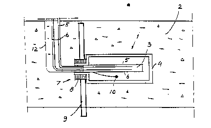
Fig. 1 schematically illustrates a test probe according
to the invention which is cast into a structural
work and

Fig. 2 schematically illustrates another embodiment of
a test probe according to the invention in a i
condition cast into its position. ' ! `

As illustrated i~ Fig. l a preferred, fixst embodiment of a
- test probe l according to the present invention consists of
such a formation which is fixable in a structutal material 2
already during the production stage. It is with other words
possible to be cas~ into e.g. concrete directly which is
unique within the moisture measurement range. The test probe

~ WO94/04910 21~ 2~ ~ S PCT/SE93/00682
-- 3 --
1, which has such a quality that it can absorb and emit
moisture in steam phase but not in liquid phase, includes an
active part 3 consisting of a hygroscopic material, said
part is enclosed in an outer, mechanical cover 4. The test
probe 1 has that quality owing to that the cover g consists
of an expanded plastic designed in such ~ way tha~ water
vapour can pass through it, but not water in a liquid phase.
The cover 4 is also intended to prevent a break down of the
active part 3 of the test probe 1, which is exerted to
pressure during casting into the concrete. The mechanical
co~er 4 is continuous as to its formation and is provided
with a suppoting means 7 in one end of the same in the form
of a threaded washer 8 ~or tightening of the test probe 1 in
a position fixing means 9 for a temporary fixing of the same
in connection with concrete casting.
.

The active part 3 of the test probe 1 which consists of a
hygroscopic material comprises in the example described of a
round bar of wood having a diameter of about 6 mm. This
material adjusts its relative humidity RF % to the relative
atmospheric humidity RF ~ of the ambient material. Two
unisolated electrodes 5 and 6 are inserted into the active
part 3 thereby in making it poss~ble to read the actual
relative atmospheric humidity RF % of the test probe 1.
These electrodes 5,6 are sticked into the active part 3 of
the test probe 1 a distance, which in the example illu-
strated amounts to about 3-6 times the diameter of the
active part 3. Those parts of the electrodes 5,6 which
extend from the test probe 1 and through the concrete 2 and
further to a resistance meter, not illustrated in the draw-
ing, are isolated. On the electrodes 5,6 the electrical re-
sistance is measured, whi.ch occurs between them, at actual
m~isture level. The resistance is indicated with a conven-
tional resistance meter at different moisture levels.

Since the magnitude of the resistance also is dependent of
the temperature at the measuring place it is measured by a
temperature indicator in the form of a thermistor 10 which
is situated between the active part 3 of the test probe and
the mechanical cover 4 and which is connected to a measuring
equipment not illustrated in the drawing by a cable 1~.

WO94/04910 ~ ~2 ~ ~6 PCT/SE93/00682

-- 4 --
Is ~hP reading of the temperature other than 20C the resis-
tance reading is compensated by aid o~ a micro-processor.

The instrument also can be equipped with an indicator which
indicates the temperature measured in C. The conversion of
the temperature corrected resistance reading to relati~e hu-
midity RF % occurs in that a resistance value for moisture
between 75-97 ~ RF calibrated forward is îed into said
micro-processor. It converts therea~ter the right value in
R~ ~ to an indicator on the measuring instrument.

In Fig. 2 is illustrated an modified embodiment of the test
probe l according to the present inve~tion. Here it is pri-
- marily the fixing itself of the test probe l ln place which
is different. Otherwise the construction is almost corres-
ponding to that test probe illustrated in Fig. l. Howe~ex,
the supporting mea~s 7 is here formed as a means of attach-
ment ll. The electrodes 5 and 6 and the transmitter cable 12
are extending through this from the thermistor l0 by an
opening 13. A round bar 14 is by its threading into the
: ` :
attachment means ll intended both to unload said cables 5,6
and 1G in tension and to fix the test probe l during its
casting into the structural mater~l 2 which consists of
concrete.
~.


I
! ' ~

Representative Drawing
A single figure which represents the drawing illustrating the invention.
Administrative Status

For a clearer understanding of the status of the application/patent presented on this page, the site Disclaimer , as well as the definitions for Patent , Administrative Status , Maintenance Fee  and Payment History  should be consulted.

Administrative Status

Title Date
Forecasted Issue Date Unavailable
(86) PCT Filing Date 1993-08-17
(87) PCT Publication Date 1994-03-03
(85) National Entry 1995-02-16
Dead Application 2000-08-17

Abandonment History

Abandonment Date Reason Reinstatement Date
1999-08-17 FAILURE TO PAY APPLICATION MAINTENANCE FEE

Payment History

Fee Type Anniversary Year Due Date Amount Paid Paid Date
Application Fee $0.00 1995-02-16
Maintenance Fee - Application - New Act 2 1995-08-17 $50.00 1995-08-04
Registration of a document - section 124 $0.00 1996-06-13
Maintenance Fee - Application - New Act 3 1996-08-19 $50.00 1996-08-16
Maintenance Fee - Application - New Act 4 1997-08-18 $100.00 1997-08-14
Maintenance Fee - Application - New Act 5 1998-08-17 $150.00 1998-08-17
Owners on Record

Note: Records showing the ownership history in alphabetical order.

Current Owners on Record
SAHLENS FUKTKONTROLL
Past Owners on Record
SAHLEN, NICKLAS
Past Owners that do not appear in the "Owners on Record" listing will appear in other documentation within the application.
Documents

To view selected files, please enter reCAPTCHA code :


To view images, click a link in the Document Description column. To download the documents, select one or more checkboxes in the first column and then click the "Download Selected in PDF format (Zip Archive)" or the "Download Selected as Single PDF" button.

List of published and non-published patent-specific documents on the CPD .

If you have any difficulty accessing content, you can call the Client Service Centre at 1-866-997-1936 or send them an e-mail at CIPO Client Service Centre.


Document
Description 
Date
(yyyy-mm-dd) 
Number of pages   Size of Image (KB) 
International Preliminary Examination Report 1995-02-16 14 303
PCT Correspondence 1996-03-18 1 26
Office Letter 1996-03-11 1 22
Office Letter 1995-12-05 1 23
Office Letter 1995-03-30 1 14
Representative Drawing 1998-01-08 1 9
Cover Page 1994-03-03 1 23
Abstract 1994-03-03 1 58
Claims 1994-03-03 2 111
Drawings 1994-03-03 2 38
Description 1994-03-03 4 253
Fees 1998-08-17 1 47
Fees 1997-08-14 1 39
Fees 1996-08-16 1 41
Fees 1995-08-04 1 48