Note: Descriptions are shown in the official language in which they were submitted.
WO 94/0~397 ~ 71 7 Pcr~lJss3/os
SYSTEM FOR SEPARATING SOLIDS FROM_A LIOUID
The present invention relates to systems for
separation of solids from liquids and particularly~ to a
cross-flow liquid/solid separation system for treating a
slurry to isolate solids and liquids for collection.
Industry generates vast amounts of unsewerable
waste streams each year which contain components which must
be removed before disposal. These components often have
value for sale or reuse. For example, in the coal
industr~, waste waters often contain significant amounts of
coal fines. Removal of the fines from the water is
difficult and expensive because of the small particulate
size of the fines and because the fines have ionic forces
which cause them to adhere to the water molecules. It is
desirable to remove the coal fines from the water because
environmental regulations prohibit the disposal of such
waste streams without proper pretreatment. In addition,
the recovered fines, and the water which is substantially
free of the fines, are valuable for reuse.
In a typical prior art filtration process, a
liquid having solids suspended therein is disposed on a
filtration medium whereupon the liquid preferentially flows
through the pores of the filtration medium, leaving a
portion of the solids deposited as a layer on the surface
of the medium. In this conventional filtration process,
the pores through the filtration medium commonly define
elongated tortuous pathways through the thickness of the
filtration medium. The mechanism of filtration then
becomes one of entrapment of the solid particulates within
the pores and consequential buildup of a layer of solids on
one surface of the medium. As is well recognized in the
art, this mode of filtration results in the passage of
substantial quantities of fine (small) solid particulates
to escape through the filtration medium with the liquid so
3S that frequently the filtrate containing the solids must
again be processed to clarify the filtrate. These fines
and other small solid particles so clog the filtration
medium as to require close attention to cleaning of the
filtration medium in order to maintain a reasonable
'~9~/0~397 PCT/~S9~/OXl~
2 1 ~
continuous system of filtration. Even so, the system is
greatly limited to throughput, size of particulates which
may be separated, rate of separation, etc.
Other prior a~t filtration methods utilize other
mechanisms. For example, in one prior art method for
separating coal fines from water, a cationic polymer is
added to the waste stream and the waste stream is initially
fed through a centrifuge. The fines exiting the centrifuge
are fed to a belt filter press to further dewater the
fines. This method desires improvement, however, because
it is essentially a batch process and the water effluent
from the centrifuge contains a relatively high solids
content and often requires substantial additional
clarification.
In the present application, it is anticipated
that the solids to be separated from the liquid may not
necessarily be suspended in the liquid as is normally the
situation with waste water streams, for example. But
r~ther, the solids may be molecular and of a molecular size
that is larger than the molecular size of the liquid. The
solid, therefore may be the solute in a solution. In the
present application, the term "slurry" has been chosen to
identify both suspensions of solids in a liquid and
solutions which contain filtrable molecules, i.e., any
flowable liquid which contains a separable component
capable of being captured by the disclosed filtration
medium and employing the disclosed filtration system and
therefore being sepàrable from the liquid.
It is therefore an object of the present
invention to provide an improved system for mechanically
isolating liquid and solid (which term includes separable
molecular moieties) components of a slurry. ~`
It is another object of the present invention to
provide a continuous system for separating solids from a
slurry.
It is a further object of the present invention
to provide a system which separates solids from a slurry
under conditions of cross-flow filtration.
W 0 94/0i397 ~ 7 1 7 PC-r/~'S93/ox12~
Accordingly, the present invention provides a
system for separating solids from a slurry wherein impro~ed
separation is achieved in a continuous operation without
the need for additives or substantial post-treatment
clarification~ In accordance wiht the present invention,
the desired separation of the liquid carrier and the solids
from the slurry are effected in a separation channel which
is divided into two sections that are disposed in tandem.
The bottom wall of the separation channel comprises a
forwardly moving filtration medium which has pores through
the thic~ness thereof which preferably are of a size less
than that will permit the passage therethrough of the
smallest anticipated solid particle contained within the
slurry. Within the first secton of the separation chanel,
the slurry is caued to flow over the surface of the
filtration medium at a flow velocity that is greater than
the rate of forward movemtn of the moving filtration
medium, with the flow velocity of the slurry being
sufficiently high as to create cross-flow filtration
conditions in this first section. Under these conditions
of slurry flow, the solids contained within the slurry are
maintained suspended within the liquid carrier and are
swept along with the slurry flow at a speed which prevents
the solids from settling onto the filtration medium in the
first section. Through the choice of pressurization of the
slurry within the first compartment of the separation
channel, or of the application of vacuum to the reverse
surface of the filtration medium, or of a combination of
pressurization and applied vacuum, liquid only is remvoed
from the slurry within the first section. Because the
solids within the slurry are prevented from entering or
closing off the pores of the filtration medium within the
first section, there is little, if any resistance to the
withdrawal of liquid from the slurry within the first
section and therefore the rate of liquid withdrawal has
been found to be phenomenally large. In the preferred
embodiment, the slurry is recvcled through the first
section on a continuous basis, with addition and removal as
~' 94/05397 PC~ 'S93/(~
a
will be explained hereinafter, so that the slurry becomes
concentrated in solids.
A portion of the concentrated slurry is directed
on a continuous basis from the first section to a second
section. The same forwardly moving foraminous member
defines the bottom wall of the second section as in the
first section, the sections being separated by a flow
restriction means. Within the second section, the
conditions of slurry flow are altered to reduce the flow of
the slurry to less than cross-flow condition and the
combination of the slurry flow rate and ~he application of
vacuum to the reverse surface of the foraminous member is
established within the second section to cause the solids
to be deposited on the exposed surface of the foraminous
medium in a filter cake layer. In the second section, the
quantity of liquid associated with the slurry has been
reduced by reason of the concentration activity within the
first section so that the rate of liquid removal required
in the second section is sufficiently low as permits this
remaining liquid, or substantially all thereof, to be
withdrawn from the slurry during the residence time of the
slurry on the forwardly moving foraminous medium within the
length of the secon section.
In accordance with one aspect of the invention,
leakage of the slurry from the upsteam end of the first
section is prevented by a first dam mèans interposed
between the housing that defines the inlet to the first
section of the separation chamber and themo~ing foraminous
,medium, to prevent backflow of the slurry along the exposed
(upper) surface of the foraminous medium. Preferably this
first dam means comprises two separated, but adjacent dams.
A similar and second dam means is employed as a flow
restriction means at the juncture between the first and
second setions of the separation channel.
A further aspect of theinvention includes the
collection an~ removal of a controlled quantity of the
liquid which is withdrawn from the slurry within the first
section and which has profgressed to the reverse surface of
~09~/0~397 PCT/~S93/0812~ l~
~ 2~ 7
the foraminous medium adjacent to the first dam means. In
accordance with this aspect of the invention, conduit means
is provided at a location adjacent to, and on the
downstream side of the first dam means and immediately
beneath the reverse surface of the foraminous medium, and
at a location adjacent to, and on the upstream side of the
second dam means and immediately beneath the reverse
surface of the foraminous medium so that regulated
quantities of the withdrawn liquid may be quickly and
immediately removed and carried away from these locations.
To this end, the conduit means is connected to a vacuum
source and provided with valve means interposed along its
length to select and regulate the quantity of withdrawn
liquid that is removed from each of these locations~. By
this means, there is prevented any accumulation of liquid
at these two locations within the system as would prevent
the desired continued flow of slurry within the sections
and as would tend to create overburdening of the means for
collection of the large quantity of liquid that is
withdrawn rapidly from the slurry through the foraminous
medium flowin~ through the first section. Further, this
selective collection and removal of the withdrawn liquid at
- the respective ends of the firs-t section aids in the
prevention of leakage of liquid from the system at these
locations. Thus, it will be recognized that the flow rate
of the slurry, the rate of travel of the foraminous medium,
and the differential pressure across the foraminous medium
as developed by the pressure head exerted by the slurry on
the foraminous medium and/or the vacuum applied to the
underside of the foraminous medium, are controlled at
different locations along the length of the separation
channel to provide optimum steady-state separation for a
given slurry or waste stream. If, as preferred, two dams
in tandem are employed at the inlet end and the downstream
end of the first section, two liquid collection conduits
are provided at each of the dam locations.
In a preferred apparatus employed in the present
invention, there is provided a source of slurry and means
U'0 9~/05397 i~ ~ ~ 2 ~ ~ ~ PCT/~:S93/0817
to convey thP slurry under controlled conditions of flow,
i.e. pressure and velocity, to a first closed separation
channel. The separation channel is divided into fi~st and
second sections with the bottom wall of both sections being
defined by a forwardly moving filtration medium, e.g. a
foraminous continuous loop belt that is trained about
suitable rolls ~drive and idler) to cause the foraminous
medium to move along an upper run that is located within,
and which definese the bottom wall of the separation
channel. Within the first sectticn, the slurry is caused
to flow first along the upper exposed surface of the
foraminous medium, thence to be directed alonga return
channel to the upsteam end of the first section where at
least a substantial portion of the recycled slurry is
caused to reenter the first section. M~ans are provided to
selectively redirect a portion of the slurry from the
return channel to the source of slurry. Generally stated,
this portion is selected to aid in establishing constant
flow conditions within the system, taking into account the
nature of the slurry, the rate of withdrawal of liquid from
the slurry within the first section (hence the
concentration of the recycled slurry), the outflow of
slurry from the first section to the second section, and
the need for the addition of "fresh" slurry from the slurry
source to achieve the desired flow conditions within the
first section of the separation channel.
As noted above, a flow restriction means, e.g. a
dam means, is provided as a separator between the first and
second sectlons of the separation channel. By means of
this dam means, the concentrated slurry is prevetned from
flowing from the firs section, past the dam means and into
the second section. A portion of the concentrated slurry
flowing through the first section of the separation channel
is withdrawn from this first section and conveyed to the
second section where the concentrated slurry is depsoited
onto the forwardly moving foraminous medium, substantially
at atmospheric pressure. The quantity of slurry withdrawn
from the first section and conveyed to the second section
i~
~ 9~/0~3g, , . PC~/~'S93/0812~ ~
2~2717 ' I 1~
is a function of several factors, including the nature of
th~ slurry, the concentration of the slurry and the desired
rate of filter cake buildup on the foraminous medium with
the second section. Within the second section, thè li~uid j~-
is withdrawn from the slurry by means of vacuum applied to
the reverse surface of the foraminous medium. Inasmuch as
the second section is at atmospheric pressure, the present
system provides the advantage of extending the length of
the second secttion of the foraminous medium to accommodate
lG attainment of steady-state continuous separation of the
liquid and solids. On the order of lS% to 25% of the
slurry reGirculating within the first section may be caused
to flow into the second section, but it is to be
recongnized that this percentage is variable and may vary
eithr up or down as necessary to sustain the desired
continuous operation of the system.
Liquid which is withdrawn from the slurry and
whcih passes through the for4aminous medium, is collected
and carried away, as by means of a vacuum system. In a
preferred embodiment, the vacuum system includes a vacuum
box which is di~ided into compartments within each of whcih
the vacuum may be controlled individually. By this means
the application of suction to the reverse surface of the
foraminous medium may be selected at various locations
along the length of the upper run of the foraminous medium
within the separtion channel (optionally as well as during
a portion fo the upper run outside the channel at the
downstream and thereof). This same vacuum system may be
employed as a collecttion vessel to receive liquid
separated from the slurry, whether or not suction is
applied, to the reverse surface of the foraminous medium.
Collected liquid may be directted to a source of reuse, or, ~-
because it is free of solids, may be sewered or directed to
a naturally flowing steam. Control of the apparatus is
effected as by microprocessor-controlled and activated
valving as is well known in the art.
Whereas the preferred system is a closed system,
in that the separation channel is designed to permit the
/ ~ PCr/~S93/081'~
pressurization of the slurry flowing through the channel,
the present sysem may include an open system in which the
slurry is flowed, at atmospheric pressure ont~ the
forwardly moving foraminous medium at a flow velocity that
is greater than the rate of forwad movement of the
foraminous medium such that cross-flow conditions are
established and maintained within the first section of the
foraminous medium. Further, it is to be recognized that
whereas the preferred embodiment of the present invention
involves the utilization of a substantial lenqth of upper
run of the foraminous medium in the first section, it is
possible to develop and maintain cross-flow conditions
within a very short distance at the upstream end of the
foraminous medium by shortening the length of the
separation channel and the return channel, hence shortening
the recycle loop. Other variations of the system will be
evident to one skilled in the art given the present
disclosure.
In a typical operation of the system of
thepresent invention, the flow rate of the slurry is
controlled at a velocity sufficient ot cause solids
contained within the slurry to be swept along with the
slurry as the slurry moves through the first section of the
separation channel. In this manner, solids are prevented
from entering or collecting to block the foraman of the
foraminous medium. A differential pressure provided across
the foraminous medium defined preferably by forces
internally of a closed channel but which may, in certain
applications, be defined by a combination of pressure and
vacuum or vacuum alone, in the first section of the
channel, causes liquid to pass out of the channel through
the foraminous medium. Different separation forces are
established within the second section of the channel,
downsteam of the first section, as by applying suction
forces to the reverse side of the foraminous medium
downstream of the first section. Further, a reduced volume
of concentrated slurry is allowed to enter the second
section. The suction forces, in combination with the
~i`
W094/0~39, t ~ 7 PCT/~iS93/081~ t
altered flow of slurry, serve ~o reduce the cross-flow
activity, cause liquid to pass through the medium, and
additionally cause solids to be captured on the exposed
upper surface of the foraminous mediu~. The deposited
layer of solids is removed from the foraminous medium ~y
gravity or mechanical action and collected. Contrary to
the known prior art cross-flow filtration systems in which
there is possible only mere concentration of the solids in
the slurry, no actual accumulation of a filter cake, and
the concentrated slurry must be collected and processed by
a different system to achieve adequate liquid removal, in
the present system, there is provided means whereby liquid
is withdrawn and a filter cake is developed continuously
under steady-state conditions as the slurry is c:Lrculated
through the sytem. In t~e prior art cross-flow filtration
~ystems, solids content of the system commonly does not
exceed a~out 25% solids, with as much as 50% solids in the
slurry being rare, due in large measure to the difficulty
in pumping hte viscous slurry. Thus, these prior art
systems require holding tanks to receive the store and
concentrated slurry, plus additional equipment and exposure
to remove further water from the slurry. In the present
system the filter ca~e at solids concentration exceeding
70% is removed continuously from the filtration medium.
Other objects, features and advantages of the
present invention will become apparent upon reading the
following detailed description and when considered in
accordance with the appended claims and accompanying
drawings, in which:
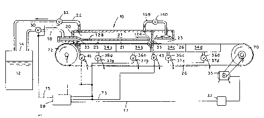
Figure 1 is a schematic diagram of a separation
system provided in accordance with the present invention;
Figure 2 is a schematic perspective view, partly
exploded, of a system embodying various features of the
present invention;
Figure 3 is a sectional view of a separation
channel suitable for use in the system of Figure 2
~employing a slightly different path of movement of the
foraminous medium); and
2 ~ PC~ S93/0812
Figure 3A is an enlarged representation of means
for dividing the separation channel along its length into
an initial length portion and a second length portion, and
is taken generally along the line 3A of Figure 3;
Figure 3~ is an enlarged represe~tation of means
for preventing back-flow of slurry in the region of the
inlet to the separattion channel, and is taken generally
along the line 3B of Figure 3; and
Figure 4 is a cross-sectonal view of the
separation channel taken generally along the line 4-4 of
Figure 3.
With reference to the drawings, in which like
reference characters refer to like parts, Figure :L shows a
schematic diagram of a system 10 for separating solids from
a slurry 12 which contains solids within a liquid carrier.
The system 10 includes a source of the slurry, such as a
tank 14, and a conduit 18 for delivering the slurry into a
separation channel 20 for separation of solids. A conduit
22 is similarly provided for return of slurry to the tank.
The separation channel 20 includes first and second
sections 21 and 23, respectively, having a bottom wall 25
defined by a foraminous medium 26. The foraminous medium
26 is positioned underneath the separation channel for
travel in the direction of the arrows as depicted in Figure
l. Control system 28 controls the flow of the slurry, the
line speed of the foraminous medium, and the differential
pressure across the foraminous medium, as esta~lished by
the pressure exerted by the flowing slurry on the
foraminous medium and/or the relative pressure underneath
the foraminous medium, to provide optimum separation
conditions for a given slurry.
The flow rate of the slurry, for example, may be 3`
controlled by a valve 30 provided on the conduit 18 and
operatively associated with the control system 28. The
line speed of the foraminous medium may likewise be
controlled, such as by a control sw.itch 32 provided between
the drive mechanism 35 of the foraminous medium and the
control system. The differential pressure across the
W094/0~397 2~ ~ ~ 71 7 PCT/~'S9~/0812' ,;,
11 1
thic~ness of the foraminous medium in the first section is 1,
established by the pressure exerted by the flowing slurry
on the foraminous medium, by the relative pressure
underneath the foraminous medium, or by a combination
thereof. The density of the slurry, the flow rate of the
slurry, the pressure within the chamber, and the line speed
of the foraminous medium primarily determine the pressure
exerted by the slurry on the foraminous medium. In a
"closed" system, the pressure within the chamber and the
flow of slurry may be independently adjusted to provide
optimum conditions for a given waste stream. Additionally,
as will be explained more fully below, some slurry may be
returned from the downstream end of the first section 21 to
the tank or recirculated to the upstram end of the section
21. To this end, a return channel 27 is provided in fluid
communication with the first section 21, a valve 33 is
provided on the conduit 22, and a flow diverter 29 is
provided in the channel 27 to control the return of slurry
to the tank or to recycle a portion to the section 21. The
relative pressure underneath the foraminous medium is
adjusted by selectively applying a vacuum supplied from a
source 31 to the underside of the foraminous medium. For
example, a vacuum box comprising a series of individually
controllable compartments 34a-34d may be provided
underneath the foraminous medium. A series of valves
36a-36d in flow communication with the vacuum compartments
and operatively associated with the control system allows
selective application of suction forces underneath the
foraminous medium. This same, or another similar, source
of vacuum may be used to convey away liquid which is
collected in the vacuum boxes through respective outlet
conduits 37a-37d. ' `
In a preferred operation, the system travels the
slurry along the first section 21 of the channel 20 at a
rate which is faster than the line speed of the foraminous,
medium and which is sufficient, in the absence of suctionor
other forces, to cause solids contained within the slurry
to be swept along wiht the slurry. These flow conditions
~0~/0~39' ~r~ PCT/~!59~/0
12
favor the flow of liquid out of the chamber through the
foraminous medium. In a preferred embodiment, no vacuum is
applied-to the underside of the foraminous medium t~rough
the first and second vacuum compartments 34a and 34b and
cross-flow velocity of the sIurry within the section 21 is
established so that substantially only liquid is removed
from the slurry in the region between the inlet 33 to the
first section 21 and a flow restricting dam 35 which
defines the separation of the first section 21 and the
second section 23. Under these conditions, essentially no
solids are deposited on the foraminous medium in this firs~
section, but rather the solids are s~ept along the length
of the section 21 and are thereby prevented from depositing
on the medium and/or from entering or blocking the foramen
of the foraminous medium. This may be accomplished, for
example by closing the valves which lead to the vacuum
compartments 34a and 34b locat~d beneath the first section
21 of the system. In the second section of the system
downsteam of the first section, between the dam 35 and the
downstream end 3~ of the separation channel, the relative
pressure, i.e vacuum, underneath the foraminous medium is
controlled by opening the valve 34c such that liquid
continues to flow through the foraminous medium but solids
are encouraged to deposit on the foraminous medium. The
withdrawal of further liquid from the solids which collect
on the medium may be e~fected by opening the valve 36d to
thereby develop suction within the compartment 34d.
In a preferred embodiment as depicted in Figure
3, there is provided a flow impeding dam 35 positoned
between the firs and second sections 21 and 23 and
depending downwardly from the top wall of the channel 20
and beteen the opposite side walls 132 and 134 thereof to
a terminal location in contact with the foraminous medium
26 which defines the lower wall of the channel. This dam
effectively serves to define the downstream end of the
first section 21 of the separation channel and the upstream
end of the second section 23 of the channel. In this
manner, the first section provides a region wherein a
W O 94/05397 21~7 1~ !'Cr/~'S93/OX12~
significant amoun~ of substantially solids-free liquid may
be separatd from the slurry to concentrate the slurry, and
the second section provides a region wherein a substantial
portion of solids may be deposited on the foraminous medium
as a filter cake and thereby separted from the slurry while
employing a single forwardly moving foraminous medium that
preferably is a continuous loop belt.
With reference to Figure 2, there is shown
further apparatus 38 for separating solids from slurry in
accordance with the present invention. The apparatus
includes a support stand 40, tank 14 which provides a
source of the slurry, an elongate separation channel 20,
and a foraminous medium 26 movably positioned beneath and
in adjacent alignmetn with th~ separation channel for
travel in the direction of the arrow A. In a preferred
embodiment, the foraminous medium is in the form of an
endless loop and is provided as described in copending U.S.
Patent application entitled "Filtration Medium Includin~
Substrate-supported Porous Membrane and Method for the
Manufacture ~hereof:, and which is incorporated herein by
reference.
Slurry is introduced from the tank 14 and into
the separation channel 20 for separation of the liquid and
solids and collection of the isolated slurry components.
Unseparated slurry components may be returned to the thank
or recirculated within the c~annel until the desired
separation is complete. To introduce slurry from the tank
14 to the separation channel 20, an inlet conduit 18 and an
in-line pump 48 are provided between the tank 14 and an
inlet manifold 50 of the channel 20. An outlet conduit 22
is provided between the tank and an outlet manifold 54 of
the channel for returning slurry to the tank 14, this
return flow being regulated ~y valve 33.
The inlet manifold 50 routes the slurry into the
separation channel for travel therealong at a flow rate
(velocity) which is greater than the rate of forward travel
of the foraminous medium. The incoming flow of slurry is
directed into the first section 21 and toward a lower wall
~09~/053972 1 ~7 l~ PCT/~'593/OXI"
14
defined by the foraminous medium 26. The foraminous medium
is trained above a drive roll 70, and a tensioning roll 72
(see Figure 2) so as to be positioned for travel below and
adjacent the separation channel and includes a drive
assembly 60 includes an electric motor Ç2 and 2 gearbcx 64
connected by a drive belt 66 to the drive roll 70. The
drive roll 70 contacts the foraminous medium in the
direction of the arrow "A" and at a selectable speed. The
roll 71 and the tensioning roll 72 (Figure 3) are provided
to guide and stretch the foraminous medium. Figure 3
depicts a slightly different path for the medium 26 and
includes an idler roll 73. As will be explained further
below, the pressure within the chamber, the flow rate of
the slurry and the line speed of the medium are controlled
by a control system 72 via various leads 73, 75 and 77 to
accomplish separa~ion of the liquid and solids. The solids
are separate by deposition along a selected portion of the
foraminous medium. A hydraulic press roll 74 is provided
adjacent the downstream end of the separation chamber and
actuable by means of a hydraulic piston-cylinder 73 to
provide a nip 79 for further removal of liquid from the
solids deposited on the foraminous medium.
With references to Figures 1, 2 and 3, the
apparatus further includes a vacuum box system comprising
individually controlled compartments 34a-34d to provide
selectable differential pressure across the thickness of
the foraminous medium which favors the flow of liquid
through the foraminous medium which favors the flow of
liquid through the foraminous medium which regulates the
deposition of solids onto the foraminous medium and which
serves to convey away the liquid which is withdrawn form
the slurry through the foraminous medium. In this manner,
a first differential pressure zone is provided along the
first section 21 of the separation channel 20 wherein
solids are discouraged from depositing on the foraminous
medium by establishing and maintaining cross-flow
conditions within this zone, and a second differential
pressure zone is provided along the second section 23
W094/0~39, ~ 71 7 PC~/~'S93/081
wherein solids are encouraged to deposit onto the
foraminous medium. In this example, the flow of liquid
from the slurry through the medium is greatest in the first
zone.
5The depicted vasuum box system includes a
plurality of vacuum compartments 36a, 36b, 36c and 36d
position~d adjacent to and below the foraminous medium to
support the foraminous medium and to selectively apply a
negative pressure to discrete por~ions of the underside of
10the foraminous medium to withdraw liquid through the
foraminous medium and to regulate the deposition of solids
onto the foraminous medium from the flowing slurry~ ~iquid
withdrawn by the vacuum compartments drains through a drain
conduit 86 in flow communication with each vacuum
15compartment to a collection tank which may be the vacuum
tank 31. With specific reference to Figure 3, each of the
vacuum compartments 34a-d is provided with a drain outlet
conduit 37a-d, respectively. Solenoid-controlled valves
39a-d are interposed along the length of each of the drain
20conduits, respectively, for control of the drainage of
liquid from each of the vacuum compartments, independently
of the application of vacuum within each of these
compartments. The drain conduits 37a-d are each connected
to the drain conduit 86 which leads in fluid communication
25to the vacuum/collection tank 31. The depicted vacuum
system also includes a pump 90 connected by a conduit 92 in
flow communication with the vacuum tank 31 to develop a
vacuum within the tank 31. As desired, one or more eductors
may be used in-lieu of the pump 90. As noted, valve
30asse~blies 36a-d are interposed alang the length of a
conduit 87 for selectively applying a negative pressure to
selected vacuum compartments. Liquid collected in the
collection tank is drained for disposal or reuse or by a
discharge pump 94 and discharge conduit 96 located at the
35drain end of the collection tank.
Wlth continued reference to Figures 1 and 2, the
control system includes a microprocessor 100 and a
plurality of electrical leads 73, 75 and 77 extending rrom
U'094/0~397 PCT/~'S93/0812~
2l42~ l ! ` ;
16
the microprocessor ~o various controlled devices. In the
depicted embodiment, the lead 73 extends to valves 33, 36a-
36d, 41 and 43, the lead 77 extends to a control swltch 32
on the electric drive motor 35, and the lead 7S extends to
the valves 30 and 33.
With re~erence now to Figures 1-3 and 4, there is
shown a preferred embodiment of the separation channel 20
including a housing 109. In this embodiment, the
separation channel includes an inlet conduit 18 in flow
communication with the inlet end of the first section 21
for introducing slurry into the separation channel. As
shown, a hemi-spherical shaped flow director 114 which
~xtends fully across the width of the first sect:ion 21 is
provided to direct slurry from the inlet conduit into the
separation channel such that the flow of the slurry is
generally downward and toward the lower wall of the channel
which is defined by the foraminous medium. As depicted in
~igure 3B t a pair of flow restricting dams 115 and 117 is
provided in the region between the flow director and the
foraminous medium 26 to seal and prevent leakage of the
slurry from the channel in this area. Liquid evacuation
channels 124a and 124b are provided downstream of the dams
115 and 117, respectively. These channels extend fully
across the width of the section ~1 and are connected to a
vacuum tank 118 by means of a conduit 119 provides for
control of the withdrawal of liquid via the channels 124a-
b. By this means, there is prevented an accumulation of
liquid adjacent these dams, thereby minimizing leakage of
liquid therepast. In like manner, liquid collected in the
channels 35a and 35b associated with the dams 35 and 38 is
also conveyed to the tank 118 via the conduit 119. Further
valve means 120b in the conduit 119 provides for control
over the withdrawal of liquid from the channels 35a and
35b.
There is also provided a pair of flow impeding
dams 35 and 38 positioned within the channel 20 and
depending downwardly from the top wall of the channel and
between the opposite side walls 132 and 134 thereof to a
~'0 94/1)~39 / 2 ~ 71 7 PCr/~!S93/0812 ~ Ff
17
terminal location in contact with the upper surface 25 of
the foraminous medium 26 which defines the lower walI S8 of
the channel. These dams effectively prevent the flow of
slurry from the first section 21 to the second section 23
while permitting the forward movement of the medium 26
therebeneath.
With further reference to Figures 1-3, upstream
of the dams 35 and 38 there is provided a funnel shaped
channel 124 located adjacent to and on the upstream slde of
the dams which connected the downstream end of the first
section 21 of the separation channel to the recirculation
channel ~7. The depicted recirculation channel 27 is
parallel to and spaced apart from the first section 21
separation channel for returning slurry to the tank or to
the beginning, i.e. upstream end, of the separation
channel. A connecting channel 128 having a selectably
positionable flow diverter 29 connects the recirculation
channel 27 to the fist section 21 of the separation channel
for recirculation of slurry to the beginning of the
separation channel. A return conduit 22 in flow
communication with the outlet manifold connects to the
recirculation channel 27 for returning slurry to the tank
14. The position of the flow diverter 2~ determines
whether slurry is recirculated or returned to the tank or
both.
Upstream of the location of the connecting
channel 124 there is provided a liquid flow diversion
conduit 159 into and through which slurry from the channel
27 may be withdrawn and directed into the upstream end of
the second section 23. Control of the flow of the slurry t
through the conduit 159 is regulated by the valve 160.
With reference now to Figure 4, the separation
channel 20 depicted in Figure 3 provides a flow path along
the sections 21 and 27, each of which is of generally
rectangular cross-section. The section 21 is defined on
three sides by interior walls 132, 133, and 134. The
foraminous medium defines the lower wall 58 of the section,
as previously explained. In one embodiment, the side walls
W09~/0~397 PCT/~'S93J081'~ ~
2~rl s
18
132 and 133 of the section 21 may be spaced apart by a~out
6.5 inches, and the distance between the top wall 134 of
this section and the bottom wall which is defined by the
foraminous medium is about 2 inches. As shown in Figure 4,
the side edges of the foraminous medium are disposed within
slots 160 and 162 defined in the bottom edges of the side
walls 132 and 133 with an effective width of about 6.5
inches of the foraminous medium being exposed to the
interior of the section 21. Appropriate seals 164 and 166
are provided within the slots 160 and 162 for sealing
against slurry flowing from the section 21 around the side
edges of the foraminous medium. The length of the first
section 21 is selected to provide the desired withdrawal of
liquid from the slurry over a selected time period - a
function of the slurry.
In a preferred embodiment as depicted in Figure
3, the foraminous medium is supported by mens of a
perforated plate 168 which serves as a top cover for the
several vacuum compartments 34a-d. Liquid withdrawn fro~
the slurry flowing through the extraction chamber flows
through the perforations 170 in the plate 168, then into
the individual vacuum boxes. Drain conduits 37c-d provided
for each vacuum compartment provides for removal of liquid
therefrom.
2S The recirculation channel 27 is also of
rectangular cross-section, and is defined by inner walls
140, 141, 142 and 143. The cross-sectional geometry of the
channel 27 prefera~ly is the same as that of the channel
210.
With continued reference to Figures 2 through 4,
a plurality of uniformly spaced apart orifice blades 150
are shown positioned along and depending form the upper
wall of the first section 21 of the channel 20. Each blade
projects into the interior of the first section of the
channel and in the depicted embodiment has a width equal to
the width of the channel. As many of the orifice blades as
required may be provided at uniformly spaced locations
along the length of the interior of the fist section 21 of
W O 94/0539? 2 I ~ 2 7 1 7 PcT/~'s93/o8l~s
19
the channel, to achieve the desired flow of the slurry.
These blades terminate at their bottom edge 157 above the
exposed inner surface 153 of the foraminous medium 26 a
selected distance, e.g. about l/2 inch, to define flow
restricting orifices spaced along the path of the flowing
slurry. These blades function in the nature of orifices
and expand the flow of slurry therepast in the separation
channel into a highly turbulent, pulsatin~ flow such that
the solids are maintained in suspension, thereby enhancing
the desired flow of the slurry along the length of the
channel. Notably, no blades are proved within the second
section 23. Further as noted previously, preferably vacuum
is applied to only the second section 23 of the channel.
This combination results in deposition of solids onto the
foraminous medium within only the second section of the
channel. It is to be recognized that vacuum may be applied
in the first zone or a combination of pressure and vacuum
may be employed in this first zone, depending upon the
desired separation effect.
Whereas there is depicted and described an inlet
to the first section 21 of the separation channel 20 in
which the incoming flow of slurry is diverted from t~e
inlet conduit 18 downwardly onto the forwardly moving
foraminous medium in the form of a "sheet" of flowing
slurry that extends fully across the width of the inlet by
means of a flow diverter, it is to be recognized that other
types of inlet flow control devices may be èmployed. Such
devices as are common in the papermaking industry may be
employed and are variously known as headboxes and/or
slices, or combinations of these. One such device is that
type depicted in U. S. Patent No. 2,756,649, which is
incorporated herein by reference. In any event, the E`
primary purpose of thee inlet devices is to present the
incoming slurry to the foraminous medium in a forwardly
flowing steam that has a flow velocity which is sufficient
to create cross-flow conditions with respect to the
forwardly flowing stream that has a flow velocity which is
sufficient to create cross-flow conditions with respect to
W094/0539, PC~/~'S9~/081 t~ ~
.~ ~ ~
~4~ 20
the forwardly moving foraminous medium. In another aspect,
the present invention may be ann "open" system in which the
slurry flowing over the foraminous medium in the~ first
section is at atmospheric pressure. In this or any
suitable system, it is of the essence of the invention that
the flow of the slurry over the medium at the upstream end
of the first section be such as develops cross-flow
conditions in which the solids within the slurry are kept
suspended within the slurry and are not allowed to
accumulate in or on the foraminous medium. The length of
the initial flow path of the slurry wherein it is under
cross-flow conditions may range from a few inches up to any
economical length. Separation efficiency may suffer when
the shorter cross-flow lengths are employed, and loner
cross-flow lengths tend to consume excessive energy for
moving of the slurry. Where the slurry is flowed onto the
foraminous medium under atmospheric pressure, but at high
velocity, it may be required that the slurry be withdrawn
at the downstream end of the first section as by a vacuum
means or the like for recirculation to the source of slurry
and/or to the upstream end of the first section. Further,
in this mode of operation, vacuum preferably is applied to
the reverse surface of the foraminous medium to aid in
liquid withdrawal from the slurry.
As mentioned previously, the flow rate o f the
slurry the rate of travel of the foraminaus medium, the
pressure head exerted by the stream on the foraminous
medium, and/or the vacuum applied on the underside of the
foraminous medium are selected to provide optimum steady-
state separation for a given slurry. To this end, it has
been experienced that for a system having an extraction
channel of the aforesaid construction and a slurry
containing water and coal fines at a solids consistency of
about 2 to 23%; the following parameters will result in
removal of about 99+% of the solids from the slurry during
a single pass of the slurry through the apparatus:
W094/05397 ~14~717 P~ 'S93/Ogl2'
. . ~.
21
Parameter Value
Pressure head 10 to 30 psi
Slurry flow rate
through first section lo to 20 ft/sec
Line speed of filter belt 1 to lG ft~m~
Vacuum 3 to 24" Hg applied
in second section
As noted above, the vacuum is applied only within
the second section 21. With reference to Figure 3, the
vacuum in the example is first applied to the foraminous
medium in the region downstream of the dam 35. The vacuum
is applied substantially uniformly to the underside of the
foraminous medium by way of the vacuum compartments 34c and
34d. To this end, it will be understood that the vacuum
compartments 34a and 34b upstream of the dam 35 preferably
do not apply vacuum to t he foraminous medium, but serve to
support the foraminous medium and as receptacles to receive
liquid which passes~through the foraminous medium upstream
of dam 35. As shown in Figure 3, a filter cake 152 of
solids is deposited onto the medium 26 commencing where
vacuum is first applied via Yacuum compartments 34c and 34d
and continuing until the desired dryness of th~ solids is
achieved. No material deposition of solids on the medium
26 occurs upstream of the dam 35. The cake 152 may be
compressed by contact by the pressure roll 74 and finally
removed from the medium 26 as by a doctor blade l90 and
collected in a receptacle 192. A brush roll l91 is
provided downstream of the roll 70 and in rotating contact
with the medium 26 for cleaning any residual particulates
from the medium.
As mentioned previously, the flow rate of the
slurry and the line speed of the foraminous medium are
controlled such that the slurry has a greater velocity than ~,
the surface speed of the foraminous medium. This causes
the slurry to be maintained in cross-flow conditions within
the first section of the channel whereby the solids are
maintained in suspension and swept along with the flow of
WO9~/0~397 ~ PCr/~'S93/08
22
the slurry in this first section 21. This flow environment
results in "cross flow" filtration, wherein only
essentially solids-free liquid is extracted from the ~lurry
and permitted to enter and pass through the foramen of the
foraminous medium in the first section 21. The pressure
head of the slurry forces the essentially solids-free
liquid through the foraminous medium for removal from the
separation channel. It will therefore be understood that
it is desirable to restrict deposition of solids onto the
foraminous medium for a sufficient length of the extraction
channel such that a large percentage of liquid may ~e
remo~ed from the slurry before the deposition of the solids
is carried out in the second section 23.
The foregoing description of certain embodiments
of the present invention has been provided for purposes of
illustration only, and it is understood that numerous
modifications or alterations may be made without departing
- form the spirit and scope of the invention as defined in
-~ the following claims.
,