Language selection

Search

Patent 2142722 Summary

Third-party information liability

Some of the information on this Web page has been provided by external sources. The Government of Canada is not responsible for the accuracy, reliability or currency of the information supplied by external sources. Users wishing to rely upon this information should consult directly with the source of the information. Content provided by external sources is not subject to official languages, privacy and accessibility requirements.

Claims and Abstract availability

Any discrepancies in the text and image of the Claims and Abstract are due to differing posting times. Text of the Claims and Abstract are posted:

  • At the time the application is open to public inspection;
  • At the time of issue of the patent (grant).
(12) Patent: (11) CA 2142722
(54) English Title: A LATCHING SYSTEM
(54) French Title: SYSTEME DE VERROUILLAGE
Status: Expired and beyond the Period of Reversal
Bibliographic Data
(51) International Patent Classification (IPC):
  • H01R 13/627 (2006.01)
  • H04M 1/02 (2006.01)
(72) Inventors :
  • HASSEMER, BRIAN J. (United States of America)
  • BEUTLER, SCOTT D. (United States of America)
  • ROBACK, KENNETH J. (United States of America)
(73) Owners :
  • MOTOROLA, INC.
(71) Applicants :
  • MOTOROLA, INC. (United States of America)
(74) Agent: GOWLING WLG (CANADA) LLP
(74) Associate agent:
(45) Issued: 1999-09-07
(86) PCT Filing Date: 1994-06-20
(87) Open to Public Inspection: 1995-02-02
Examination requested: 1995-02-16
Availability of licence: N/A
Dedicated to the Public: N/A
(25) Language of filing: English

Patent Cooperation Treaty (PCT): Yes
(86) PCT Filing Number: PCT/US1994/006926
(87) International Publication Number: WO 1995003642
(85) National Entry: 1995-02-16

(30) Application Priority Data:
Application No. Country/Territory Date
08/095,773 (United States of America) 1993-07-20

Abstracts

English Abstract


The latching system of the present invention uses a ribbed (301, 302) latch
(300) molded into the battery housing, a depression latch
(504) molded into the radiotelephone housing, and rail connectors (220) 320)
molded into the radiotelephone housing to connect a battery
(350) to a radiotelephone (200). The battery housing slides along the rail
connectors until the battery housing latch (300) engages into the
radiotelephone latch (210). The battery housing (350) is removed from the
radiotelephone housing (200) by depressing the upper portion
(300) of the battery housing latch, than rotating it out of the depression
latch (200) and allowing the battery housing to be slid off the
radiotelephone housing (200).


French Abstract

Le système de verrouillage de la présente invention utilise un verrouillage (300) à nervures (301, 302) moulé sur le logement de la batterie, un verrouillage à dépression (504) moulé dans le logement du radiotéléphone et des connecteurs à rails (220, 320) moulés dans le logement du radiotéléphone pour relier une batterie (350) à un radiotéléphone (200). Le logement de la batterie glisse le long des connecteurs à rails jusqu'à ce que le verrouillage dulogement de la batterie (300) s'engage dans le verrouillage du radiotéléphone (210). Le logement de la batterie (350) est enlevé du logement du radiotéléphone (200) en pressant sur la portion supérieure (300) du verrouillage du logement de la batterie et en la faisant tourner ainsi hors du verrouillage à dépression (200) et en permettant au logement de la batterie de se dégager en glissant du logement du radiotéléphone (200).

Claims

Note: Claims are shown in the official language in which they were submitted.

-7-
What is claimed is:
1. A latching system of a power device for connecting said power device to an
electronic device, said power device comprising an outer housing having an
inner surface and an outer surface, the latching system comprising:
a latch member integrally associated with said outer housing of said
power device, said latch member extending along a first axis from a distal end
to a proximal end and including at least one rib member projecting from said
inner surface of said outer housing along a second axis, said at Least one rib
member having a protrusion adapted to fit into a depression in said electronic
device far positively coupling said power device to said electronic device;
an attachment member integrally associated with said latch member
for coupling said latch member to said outer housing and enabling rotation of
said latch member; and
coupling elements positioned along at least one edge of said outer
housing, said coupling elements being adapted to intercouple with coupling
elements of said electronic device.
2. The latching system according to Claim 1 wherein said latch member is
adapted to rotate around a third axis when force is applied to said distal end
of
said latch member.
3. The latching system according to Claim 1 wherein said protrusion is
adapted to be released from said depression in said electronic device when
force is applied to said distal end of said latch member.
4. The latching system according to Claim 1 wherein said protrusion further
includes at least a first edge being angled and wherein the depression further
includes a first edge being angled such that, when the power device is coupled
to the electronic device, the first edge of said protrusion at least
temporarily
contacts the first edge of the depression.
5. The latching system according to Claim 1 wherein said coupling elements
are adapted to prevent movement of said power device along said third axis.
6. A latching system of a power device for connecting said power device to an
electronic device, said power device comprising an outer housing having an
inner surface and an outer surface, the latching system comprising:

-8-
a latch member integrally associated with said outer housing of said
power device, said latch member extending along a first axis from a distal end
to a proximal end and including at least one rib member projecting from said
inner surface of said outer housing along a second axis, said at least one rib
member having a protrusion at said proximal end adapted to fit into a
depression in said electronic device for positively coupling said power device
to said electronic device, said protrusion being released from said depression
in said electronic device when force is applied to said distal end of said
late;
an attachment member integrally associated with said latch member
far coupling said latch member to said outer housing and enabling rotation of
said latch member around a third axis when force is applied to said distal end
of said latch member; and
coupling elements positioned along an edge of said outer housing, said
coupling elements adapted to intercoupled with coupling elements of said
electronic device for preventing movement of said power device along said
third axis.
7. A latching system of a power device for connecting said power device to an
electronic device, said power device comprising an outer housing having an
inner surface and an outer surface, the latching system comprising:
a latch member integrally associated with said outer housing of said
power device, said latch member extending along a first axis from a distal end
to a proximal end and including at least one rib member projecting from said
inner surface of said outer housing along a second axis, said at least one rib
member having a cut-out area extending through at least a portion of said at
least one rib and being adapted to fit into a depression in said electronic
device for positively coupling said power device to said electronic device;
an attachment member integrally associated with said latch member
for coupling said latch member to said outer housing and enabling rotation of
said latch member around a third axis; and
coupling elements positioned along at least one edge of said outer
housing, said coupling elements being adapted to intercoupled with coupling
elements of said electronic device.

-9-
8. The latching system according to Claim 7 wherein said latch member is
adapted to rotate around a third axis when force is applied to said distal end
of
said latch member.
9. The latching system according to Claim 7 wherein said protrusion is
adapted to be released from said depression in said electronic device when
force is applied to said distal end of said latch member.
10. The latching system according to Claim 7 wherein said protrusion further
includes at least a first edge being angled and wherein the depression further
includes a first edge being angled such that, when the power device is.coupled
to the electronic device; the first edge of said protrusion at least
temporarily
contacts the first edge of the depression.

Description

Note: Descriptions are shown in the official language in which they were submitted.


Y. ,.'
1~'O 95103642 PCTIUS94/U6926 ' '
s~- r
A, LATCHIhIG SYSTEM
~f ~e Ia~v~iarn
Y
t
The present invention relates generally to the field of
latches and particularly to battery housing latches.
~:d c~f t~ Inv~tion
1 0 To be used in a portable manner, electronic devices
require batteries for p~wer. Typically, the batteries are of the
rechargeable type and are renxov~ble in order to be placed in a
battery charger to be recharged or to be disposed of once ,
depleted.
1 5 Tn order to attach the battery, typically contained in a
housixig, to the electr~nic device; a latch mechanism must be v
used. This latch gay be of the type requiring the housing and .
the latch be assembled efter being molded separately, This
type of Latch requires greater complexity, labor, and cost to
2 0 produce. 'here is a resulting need for a latch that is molded in
the housing to reduee the cost of the device:
Sexy of t~xe ~nventi~n
2 S, The latching system of the present invention connects a
first dwice to a second device. Tlhe system is comprised of a
first latch coupled to the fist device. The first latch
comprising at least one protrusion that extends substantially
perpendicular to a plane parallel to the farst device. A second
3 0 latch is coupled to the second device. The second latch is 5;:-.
comprised of a pocket having a size such that the protrusion
rests within the pocket when the first device is brought into
contact with the second device. At least two sides of each of the
first and second devices . are coupled by means for coupling.
35 .

i
w0 9a/Q3642 ~ ..,.,
PCT/ITS94I06926
I-::
.. .
l3rieef °pta~~ of the Draw ng~
".
FIG. 1 shows a typical radiotelephone that incorporates
s.
the latching system of the present invention.
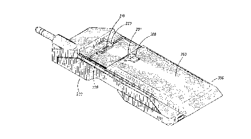
FIG. 2 shows a perspective view of the radiotelephone
housing incorporating the' latch of the present invention.
FIG. 3 shows a perspective view of the battery housing
incorporating the latch of the present invention.
FIGs. 4-1, 4-2, and 4-~ show cross-sectional/operational
1 0 views of the latches of the battery housing and the telephone
housing.
FIGS. 5-1:, 5=2, and 5-3 show cross-sectional/operational
views of an alternate embodiment of the present invention.
1 5 I)etaile~d °pt~on ofthe ~bo~nent
The latch system of the present invention is molded into
the housings of the battery and radiotelephone. This reduces
the complexity and thus the cost of the radiotelephone. The
2 0 subsequent discussion of the present invention utilizes a
typical radiotelephone; such as is illustrated in FIG. I.
I3owever, the present invention can be used on any radio or
other battery powered dovice that would benefit from a molded
latching system:
2 5 FIG. 3 illustrates the battery housing Latch (300) of the
present invention: This latch (300) is comprised of two ribs (301
and 302) that) in the preferred embodiment, extend the length
of the latch (300). The ribs (301 and 302) are substantially
perpendicular to the back of the housing. I~owever, minor
3 0 angling of these ribs (30~ and 302) in alternate embodiments ~-. ,
would not affect the performance of the Latch (300). t~Iso in the ' -
preferred embodiment, these ribs (301 and 302) are angled
such that their height above the battery housing back '
increases as they extend from the housing top (303). Alternate
3 5 embodiments would use one or more ribs.
At the point farthest from the battery housing top (303),
the ribs (301 and 302) have protrusions (304 and 305) that are in

WO 95/03642 PCTIUS94/06926 ~'=.''
<",
G:r
_3_ ;
the same plane as the ribs (301 and 302) but extend slightly
above the height of the ribs (301 and 302). The protrusions (304
and 305) extend from the ribs (301 and 302) via an angled
surface. This surface is angled back at a 45° angle from the
S vertical. Alternate embodiments could change this angle or
have the protrusion at a 90° angle to the rib. The portion of the
protrusion facing the end of the latch drops o~ at a 90° angle to
the end of the latch (300). This angle could also be di~'erent for
other embodiments.
1 0 The battery housing latch (300) is surrounded by a cut-
out area (310) so that it is attached to the battery housing only
by a thin, controlled section of material (311) extending along a
crosswise axis, slightly angled in the preferred embodiment,
through the latch (300). This material (311) is molded into the
I S latch (300) and battery housing (350).
The cut-out section (310), in conjunction with the
material (311) connecting th:e Latch (300) to the battery housing
(350), allows tl~e latch (300) to rotate a Limited amount around
the cress-wise axis. V6~hen the top (201) of the Latch (300) is
2 0 depressed on the rear of the housing (see FIG. 2, reference
201)) the protrusion portions (304 and 305) of the latch (300) are
raised up slightly due to the front portion of the latch (300)
being depressed and the latch (300) pivotir~g on the ribs (301
and 302). As will be shown later, this rotation facilitates the
2 5 removal of the battery housing (350) from the radiotelephone
housing (200).
FIG. 2 shows a view of the radiotelephone housing latch
(230) of the present invention. The radiotelephone housing
back contains a depression (210) forming a pocket that is
3 0 raised above the radiotelephone housing back. This depression ~::-__
~:._:_
(210) is located towards the top of the radiotelephone housing '°
i
back. The front edge of the depression (420 in FIG. 4-1) is
,.
angled 45° from the vertical. This is the edge that will contact
the leading edge of the battery housing latch (300) as it is slid
3 5 into place. The depression (210) is just large enough to accept
the protrusions (304 and 305) of the battery housing latch (300).

V6t~ 95/03642 PCT/US94106926
-4-
The tolerances of the depression's dimensions must be
small since the battery housing latch (300) cannot have room
to move around. This would cause a rattling noise when the M
radiotelephone is moved and would give the radiotelephone a
lo~,v quality appearance to a user.
The sides of both the battery housing (350) and the ,
radiotelephone housing (200) have rail connectors (220 and
320) to connect the sides of the housing to each other. The
connectors (220 and 320) on each housing are thin, elongated
1 0 protrusions from the side of the surfaces. The rail connectors
(220. and 320) on each housing (200 and 350) are arranged such
that the rail connectors (320) on the battery housing (350) are
situated below the rail connectors (220) on the radiotelephone
housing (200) when the two housings (200 and 350) are brought
1 5 into contact. This permits the two housings (200 and 350) to
move in only a back and forth direction along an axis
extending through the length of the radiotelephone.
In operation, the battery housing (350) is brought into
contact with the radiotelephone housing (200) so that the side
2 0 rail connectors engage. The battery housing (350) is then slid
along the back of the radiotelephone housing (200) so that the
top (303) of the battery housing is moved towards the top of the
radiotelephone housing (403). This movement is illustrated in
FIG.. 4-1.
2 5 then the angled edges (410 and 420) of the protrusion
(41~) and the depression (210) contact each other, as illustrated
in FIG. 4-2, the battery housing latch is forced to rotate
upwards on the protrusion end. The battery housing latch
pivots about the 'point of contact of the front edge of the ,
3 0 depression and the ribs of the battery housing latch. This 3,
illustration rna.kes it apparent that the angled surfaces (410
and 420) provide smoother operation of the latch system of the
present invention. If these surfaces were each at 90°. angles, ' .
the user installing the battery would have to use greater force
3 5 to engage the latching mechanisan.
FIG. 4-3 shows the latches of the battery housing and
the radiotelephone housing engaged. The protrusion of the

~z:
w0 95/03642 PCTIUS9410b926
battery housing latch rests in the depression of the ~
radiotelephone housing Latch. The vertical portion (430) of the
rear of the battery housing Latch contacts the vertical portion
(43I) of the rear edge of the radiotelephone housing Latch. This
makes it difficult to remove the battery housing since the rail
contacts only permit movement in a back and forth direction.
fihese angles resist such a movement. The top of the rear
portion of the protrusion has a 77~ angle to reduce latch
deformation when. the radiotelephone experiences impacts
I 0 such as from a drop.
In order to remove the battery housing frown the
radiotelephone housing, the front portion of the battery
housing Latch is depressed. This causes the battery hausing
latch to pivot about the point of contact of the front edge of the
1 5 depression and the ribs of the battery housing Latch. This
rotating action raises the protrusion from the depression and
allows the battery housing to be slid back along the rail
connectors and then lifted free of the radiatelephone housing.
An alternate embodiment of the latching system of the
2 0 present invention is illustrated in FIGs. 5-1 through 5-3. This
embodiment uses the same depression (504) and rail
connectors of the preferred embodiment. Additionally, the
battery housing latch is coupled to the battery housing in the
same rotational manner. The alternate embodiment,
2 5 however, replaces the rubs that extend the length of the battery
housing latch with at least two shorter, flexible ribs (500) that
have approximately the same thickness as the preferred
embodiment ribs. Far clarity, only one rib (500) is shown in the
figures. ''These ribs (500) gel their flexibility from an angled
3 0 cutout (501) extending lengthwise through a large portion of
the rib (500). ~-
'I'his alternate embodiment operates by the front edge
r'
(502) of the depression (504) forcing the ribs (500) to llex
upwards as seen in FIG. 5-2. The battery housing is latched
3 5 when the tip (503) of the rib (500) is resting in the depression as
illustrated in FIG. 5-3. Due to the raised position of the
depression (50~), the rib (500) is not allowed to re-extend to its

w0 95103642 PC'~IUS94/06926
~~.2~~~ 6 ~ j
i
1
original position. The rib (500)) therefore, is applying
downward pressure on the inside edges of the depression
(504), thus holding the battery housing in place. M
The latching systean of the present invention enables a
latch to be molded into the material of the devices to be
connected together. This reduces the labor required to
assemble a device, thus reducing the cost associated with the
device.

Representative Drawing
A single figure which represents the drawing illustrating the invention.
Administrative Status

2024-08-01:As part of the Next Generation Patents (NGP) transition, the Canadian Patents Database (CPD) now contains a more detailed Event History, which replicates the Event Log of our new back-office solution.

Please note that "Inactive:" events refers to events no longer in use in our new back-office solution.

For a clearer understanding of the status of the application/patent presented on this page, the site Disclaimer , as well as the definitions for Patent , Event History , Maintenance Fee  and Payment History  should be consulted.

Event History

Description Date
Inactive: IPC expired 2015-01-01
Inactive: IPC from MCD 2006-03-11
Time Limit for Reversal Expired 2002-06-20
Letter Sent 2001-06-20
Grant by Issuance 1999-09-07
Inactive: Cover page published 1999-09-06
Inactive: Final fee received 1999-06-02
Pre-grant 1999-06-02
Notice of Allowance is Issued 1999-03-30
Letter Sent 1999-03-30
Notice of Allowance is Issued 1999-03-30
Inactive: Status info is complete as of Log entry date 1999-03-23
Inactive: Application prosecuted on TS as of Log entry date 1999-03-23
Inactive: Approved for allowance (AFA) 1999-03-04
All Requirements for Examination Determined Compliant 1995-02-16
Request for Examination Requirements Determined Compliant 1995-02-16
Application Published (Open to Public Inspection) 1995-02-02

Abandonment History

There is no abandonment history.

Maintenance Fee

The last payment was received on 1999-03-19

Note : If the full payment has not been received on or before the date indicated, a further fee may be required which may be one of the following

  • the reinstatement fee;
  • the late payment fee; or
  • additional fee to reverse deemed expiry.

Please refer to the CIPO Patent Fees web page to see all current fee amounts.

Fee History

Fee Type Anniversary Year Due Date Paid Date
MF (application, 4th anniv.) - standard 04 1998-06-22 1998-05-01
MF (application, 5th anniv.) - standard 05 1999-06-21 1999-03-19
Final fee - standard 1999-06-02
MF (patent, 6th anniv.) - standard 2000-06-20 2000-05-03
Owners on Record

Note: Records showing the ownership history in alphabetical order.

Current Owners on Record
MOTOROLA, INC.
Past Owners on Record
BRIAN J. HASSEMER
KENNETH J. ROBACK
SCOTT D. BEUTLER
Past Owners that do not appear in the "Owners on Record" listing will appear in other documentation within the application.
Documents

To view selected files, please enter reCAPTCHA code :


To view images, click a link in the Document Description column. To download the documents, select one or more checkboxes in the first column and then click the "Download Selected in PDF format (Zip Archive)" or the "Download Selected as Single PDF" button.

List of published and non-published patent-specific documents on the CPD .

If you have any difficulty accessing content, you can call the Client Service Centre at 1-866-997-1936 or send them an e-mail at CIPO Client Service Centre.


Document
Description 
Date
(yyyy-mm-dd) 
Number of pages   Size of Image (KB) 
Cover Page 1995-11-11 1 22
Abstract 1995-11-11 1 82
Description 1995-11-11 6 364
Claims 1995-11-11 3 162
Drawings 1995-11-11 5 242
Cover Page 1999-09-01 2 89
Representative drawing 1999-09-01 1 39
Representative drawing 1998-01-08 1 35
Commissioner's Notice - Application Found Allowable 1999-03-30 1 164
Maintenance Fee Notice 2001-07-18 1 178
Correspondence 1999-06-02 1 28
Fees 1997-03-25 1 97
Fees 1996-03-26 1 96
Prosecution correspondence 1995-02-16 3 133
National entry request 1995-02-16 6 234
International preliminary examination report 1995-02-16 1 52