Language selection

Search

Patent 2143303 Summary

Third-party information liability

Some of the information on this Web page has been provided by external sources. The Government of Canada is not responsible for the accuracy, reliability or currency of the information supplied by external sources. Users wishing to rely upon this information should consult directly with the source of the information. Content provided by external sources is not subject to official languages, privacy and accessibility requirements.

Claims and Abstract availability

Any discrepancies in the text and image of the Claims and Abstract are due to differing posting times. Text of the Claims and Abstract are posted:

  • At the time the application is open to public inspection;
  • At the time of issue of the patent (grant).
(12) Patent: (11) CA 2143303
(54) English Title: PADLOCKS
(54) French Title: CADENAS
Status: Expired and beyond the Period of Reversal
Bibliographic Data
(51) International Patent Classification (IPC):
  • E05B 67/00 (2006.01)
  • E05B 17/00 (2006.01)
  • E05B 17/20 (2006.01)
  • E05B 67/02 (2006.01)
  • E05B 67/04 (2006.01)
  • E05B 67/38 (2006.01)
(72) Inventors :
  • LONG, RUSSELL PHILLIP (Australia)
(73) Owners :
  • R.P.L. INDUSTRIES (INTERNATIONAL) PTY. LTD.
  • R.P.L. INDUSTRIES PTY. LTD.
(71) Applicants :
  • R.P.L. INDUSTRIES PTY. LTD. (Australia)
(74) Agent: GOWLING WLG (CANADA) LLP
(74) Associate agent:
(45) Issued: 2004-10-12
(86) PCT Filing Date: 1993-08-18
(87) Open to Public Inspection: 1994-03-03
Examination requested: 2000-06-07
Availability of licence: N/A
Dedicated to the Public: N/A
(25) Language of filing: English

Patent Cooperation Treaty (PCT): Yes
(86) PCT Filing Number: PCT/AU1993/000421
(87) International Publication Number: WO 1994004781
(85) National Entry: 1995-02-24

(30) Application Priority Data:
Application No. Country/Territory Date
PL4315/92 (Australia) 1992-08-26

Abstracts

English Abstract


A padlock has a rotatable outer body part (24) which prevents the application
of torque from a wrench to force the shackle
(4) open. One or both ends of the padlock are also configured to prevent
application of a wrench, the configuration being generally
conical configuration (28) preferably at least at the shackle end (4) of the
body of the padlock.


Claims

Note: Claims are shown in the official language in which they were submitted.

-5-
The Embodiments Of The Invention In Which An Exclusive Property Or Privilege
is
Claimed Are Defined As Follows:
1. A padlock comprising a body having a longitudinal axis and a shackle
mounted on the body for movement between a closed, locked position and an
open,
released position, wherein the body comprises an inner body part which mounts
the
shackle and an associated locking mechanism, and an outer body part mounted on
the
inner body part for relative rotation about the inner body part about the
longitudinal
axis of the body, said outer body part having a length sufficient to shield
the inner
body part against the application of a torque acting about the longitudinal
axis of the
body to force the shackle of the padlock, and the inner body part at the
shackle end of
the body having a generally conical formation having sides extending around,
and
tapering towards, said longitudinal axis whereby the application of the jaws
of a
wrench to the opposite sides of the body and shackle is impeded by the
generally
conical formation when the shackle is in the locked position.
2. A padlock according to claim 1, wherein the said formation is a generally
conical formation at the end of the inner body part remote from the shackle
end.
3. A padlock according to claim 1, wherein the conical formation is cut away
at
one side to permit the shackle to swing between said open and closed
positions.
4. A padlock according to claim 1, further comprising another formation at the
other end of the inner body part remote from the shackle end, said another
formation
being generally conical.
5. A padlock according to claim 4, wherein the conical formation at the
shackle
end of the inner body part is cut away at one side to permit the shackle to
swing
between said open and closed positions.
6. The padlock of claim 1, wherein said outer body comprises a generally
convex
shape.

-6-
7. The padlock of claim 1, wherein said outer body comprises a generally
concave shape.
8. A padlock according to claim 1, wherein the said formation is a generally
spheroidal formation on the inner body part at the shackle end of the body.
9. A padlock comprising a body and a shackle mounted on the body for
movement between a closed, locked position and an open, released position,
wherein
the body comprises an inner body part which mounts the shackle and an
associated
locking mechanism, and an outer body part mounted on the inner body part and
having a generally curved shape to prevent the application of a torque acting
about the
longitudinal axis of the inner body part to force the padlock, and the body
having at
least at one end portion a formation around the shackle impeding the
application of a
wrench to the body and to deflect hammer blows to the body by having a
generally
conical surface around the shackle and tapering toward and encompassing a
portion of
a distal the end of the shackle when the shackle is in the closed position.
10. A padlock according to claim 9, further comprising means mounting the
outer
body part on the inner body part for rotation about the longitudinal axis of
the inner
body.
11. The padlock of claim 9, wherein said curved shape of said outer body is
generally convex.
12. The padlock of claim 9, wherein said curved shape of said outer body is
generally concave.
13. The padlock of claim 9, wherein said curved shape of said outer body is
generally cylindrical.
14. A padlock according to claim 9, wherein said formation around said shackle
is
generally conical with a cutaway section to permit said shackle to swing
between said
open and closed positions.

-7-
15. A padlock according to claim 9, wherein said formation around said shackle
is
generally spheroidal.
16. A padlock movable between an open, released position and a closed, locked
position for securing an article, said padlock comprising:
an inner body containing an associated locking mechanism;
an outer body mounted around said inner body along its longitudinal axis and
adapted
to resist the application of torque acting about such axis; and
a shackle comprising a pair of arms joined by a connecting member, said arms
and
connecting member defining an aperture therebetween for receiving a component
to
be held by said padlock, said shackle being mounted at one end portion of said
padlock;
said end portion having sloping surfaces forming a generally conical shape
about said
shackle when in said closed position adapted for impeding the application of a
wrench
to the ends of said padlock and restricting said aperture such that, in rise,
space
between said component and said padlock is minimized to resist insertion of a
tool for
prying open said padlock.
17. The padlock of claim 16, wherein said outer body is cylindrical.
18. A padlock comprising a body having a longitudinal axis and a shackle lying
in
a plane extending in the same direction as said axis and mounted on the body
for
movement between a closed, locked position and an open, released position,
wherein
the body comprises an inner body part which mounts the shackle and an
associated
locking mechanism, and an outer body part mounted on the inner body part for
relative rotation about the inner body part about the longitudinal axis of the
body, said
outer body part having a length sufficient to shield the inner body part
against the
application of a torque acting about the longitudinal axis of the body to
force the
shackle of the padlock, and the inner body having an end portion comprising a
generally conical formation having surfaces on each side of said shackle plane
and

-8-
sloping from said body towards said axis so that the surfaces have no
opposing,
substantially parallel surfaces, whereby the application of the jaws of a
wrench to the
opposite sides of the body and shackle are impeded.
19. The padlock of claim 18, wherein said outer body part is annular.
20. The padlock of claim 18, wherein said formation of said end portion has a
cutaway section to permit said shackle to swing between said open and closed
positions.

Description

Note: Descriptions are shown in the official language in which they were submitted.


WO 94/04781 PCT/AU93/00421
-1-
PADLOCKS
The present invention relates to padlocks.
Conventional padlocks are relatively easy to force open. Usually, all that
is necessary is to separately grip the body of the padlock and the bolt or
shackle
of the padlock and to force the shackle open from the body. Even hardened
padlocks can be forced in this way by using a suitable wrench.
According to the present invention there is provided a padlock comprising
a body and a shackle mounted on the body for movement between a closed,
locked, position and an open, released condition, wherein the body comprises
an
inner body part which mounts the shackle and an associated locking mechanism,
and an outer body part mounted on the inner body part for rotation about the
longitudinal axis of the body, said outer body part having a length sufficient
to
shield the inner body part against the application of a torque acting about
the
longitudinal axis of the inner body part to force the padlock, and the body
having
at least at one end portion a formation which progressively reduces in cross-
sectional dimension whereby to impede the application of a wrench to the body
such that the jaws of the wrench are applied to the opposite ends of the body.
In a preferred embodiment, the said formation is a generally conical
formation on the inner body part at the shackle end of the body. Alternatively
or in addition the said conical formation may be at the end of the inner body
part
remote from the shackle end.
Embodiments of the invention will now be described, by way of example
only, with reference to the accompanying drawings in which:-

WO 94/04781 PCT/AU93/00421
-2-
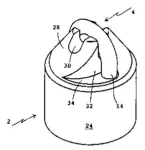
Figure 1 is a perspective view of a padlock in accordance with the
preferred embodiment of the invention;
Figure 2 is a longitudinal section through the padlock to show ,
schematically the operating components, a rotatable outer body part being
omitted for the sake of clarity;
Figure 3 is a longitudinal section showing the mounting of the outer body
part on the inner body part; and
Figures 4 to 6 are perspective views showing further embodiments of the
invention.
The padlock shown in Figures 1 to 3 of the accompanying drawings
comprises a body 2 and a curved bolt or shackle 4. The body 2 consists of an
inner body part 6 of a substantially cylindrical shape. The inner body part
has
diametrically-opposed longitudinally extending bores 8,10 which receive
opposed
arms 12, 14 of the shackle 4. The arm 12 of the shackle is longer than the arm
14 and is displaceable in the bore 8 between an inner locked position in which
the
shorter arm 14 is within the bore 10, and an outer released position in which
the
end of the shorter arm 14 is fully withdrawn from the bore 10 to permit the
shackle 4 to be applied to an article to be secured. The shackle 4 is held in
its
locked condition by locking means 16 which engage into recesses 18 on the
inner
surfaces of the arms 12, I4. The locking means 16 is releasable by actuation
of
a rotary lock mechanism 20 mounted within the inner body part 6. A key for
releasing the lock mechanism 20 is inserted into the lock mechanism from the
underside of the inner body part 6. In the open condition of the shackle 4,
the
locking means 16 engages within a further recess 22 formed at the lower end
portion of the longer arm 12 to retain the shackle 4 against withdrawal from
the
body part 6 and to permit the shackle to swivel about the axis of the longer
arm
12. The lock mechanism 20 and the locking means 16 can be of substantially
conventional construction and will not be described in ~Etail herein.

WO 94/04781 ~ PCT/AU93/00421
-3-
An outer body part 24 is rotatably mounted on the inner body part 6 by
bearings 26. The outer body part 24 is also of substantially cylindrical form
and
extends over the entire cylindrical outer surface of the inner body part 6.
The
cylindrical outer surface of the outer body part 24 and its rotatable mounting
on
the inner body part 6 prevents a wrench from being applied to the body to
provide a reaction force acting about the longitudinal axis of the body in
opposition to a force applied to the shackle 4 in an attempt to force open the
shackle.
We have also determined that for proper security it is necessary to
configure the body so that a wrench cannot be applied to the body with the
ends
of the body held firmly between the jaws of the wrench. In the embodiment
shown this is achieved by forming the shackle end portion of the body with a
generally conical shape which provides a minimum of surface area on which a
wrench jaw can grip. The conical end portion 28 is formed as an extension of
the
inner body part 6 and includes a recess for receiving the looped part of the
shackle and a passage 30 which intersects that recess for receiving a
component
such as a chain link to be held by the shackle 4. In the embodiment shown, the
conical end portion 28 is cut-away at 32 adjacent the bore 10 for the shorter
arm
14 of the shackle 4. This cut-away portion 32 enables the shackle 4 to be
swung
open without the necessity of providing the shackle 4 with longitudinal
movement
sufficient to enable the end of the shorter arm 14 to clear the conical
formation.
Although this cutaway portion 32 does provide a surface 34 generally
transverse
to the longitudinal axis of the body, this surface is very small and is most
unlikely
to represent an area on which a sufficient grip could be obtained, especially
as it
is at the edge of the body. However, this surface 34 could, if necessary, be
inclined at an acute angle to the longitudinal axis of the body, for example
by
being sloped downwardly towards the outer edge of the body in order to ensure
that it is not parallel to a surface at the opposite end of the body. In an
alternative configuration, the shackle 4 can be constructed to have sufficient
longitudinal movement to permit the shorter arm 14 to be raised clear of the
conical formation without the need for the cut-away portion.

WO 94/04781 ~. ~ PCT/AU93/00421
_4_
The rotatable outer body part 24 may have a shape other than cylindrical.
For example as shown in Figure 4 the outer body part 24 is of convex form and
in Figure 5 it is of concave form. In each case, the outer body part 24 is of
annular section and is rotatably mounted on the inner body part.
In the embodiment shown in Figure 6, the opposite end of the inner body
part is also provided with a conical formation 36 which minimises at that end
the
transverse surface area on which the jaw of a wrench can grip.
The embodiments have been described by way of example only and
modifications are possible within the scope of the invention.
t

Representative Drawing
A single figure which represents the drawing illustrating the invention.
Administrative Status

2024-08-01:As part of the Next Generation Patents (NGP) transition, the Canadian Patents Database (CPD) now contains a more detailed Event History, which replicates the Event Log of our new back-office solution.

Please note that "Inactive:" events refers to events no longer in use in our new back-office solution.

For a clearer understanding of the status of the application/patent presented on this page, the site Disclaimer , as well as the definitions for Patent , Event History , Maintenance Fee  and Payment History  should be consulted.

Event History

Description Date
Time Limit for Reversal Expired 2007-08-20
Letter Sent 2006-08-18
Inactive: IPC from MCD 2006-03-11
Inactive: Late MF processed 2005-08-24
Letter Sent 2005-08-18
Grant by Issuance 2004-10-12
Inactive: Cover page published 2004-10-11
Pre-grant 2004-07-14
Inactive: Final fee received 2004-07-14
Notice of Allowance is Issued 2004-06-16
Letter Sent 2004-06-16
Inactive: Approved for allowance (AFA) 2004-06-08
Letter Sent 2004-05-13
Amendment Received - Voluntary Amendment 2004-04-29
Reinstatement Requirements Deemed Compliant for All Abandonment Reasons 2004-04-29
Reinstatement Request Received 2004-04-29
Inactive: Abandoned - No reply to s.30(2) Rules requisition 2003-12-16
Inactive: S.30(2) Rules - Examiner requisition 2003-06-16
Amendment Received - Voluntary Amendment 2000-09-29
Letter Sent 2000-07-19
Inactive: Status info is complete as of Log entry date 2000-07-18
Inactive: Application prosecuted on TS as of Log entry date 2000-07-18
Request for Examination Requirements Determined Compliant 2000-06-07
All Requirements for Examination Determined Compliant 2000-06-07
Application Published (Open to Public Inspection) 1994-03-03

Abandonment History

Abandonment Date Reason Reinstatement Date
2004-04-29

Maintenance Fee

The last payment was received on 

Note : If the full payment has not been received on or before the date indicated, a further fee may be required which may be one of the following

  • the reinstatement fee;
  • the late payment fee; or
  • additional fee to reverse deemed expiry.

Please refer to the CIPO Patent Fees web page to see all current fee amounts.

Owners on Record

Note: Records showing the ownership history in alphabetical order.

Current Owners on Record
R.P.L. INDUSTRIES (INTERNATIONAL) PTY. LTD.
R.P.L. INDUSTRIES PTY. LTD.
Past Owners on Record
RUSSELL PHILLIP LONG
Past Owners that do not appear in the "Owners on Record" listing will appear in other documentation within the application.
Documents

To view selected files, please enter reCAPTCHA code :


To view images, click a link in the Document Description column. To download the documents, select one or more checkboxes in the first column and then click the "Download Selected in PDF format (Zip Archive)" or the "Download Selected as Single PDF" button.

List of published and non-published patent-specific documents on the CPD .

If you have any difficulty accessing content, you can call the Client Service Centre at 1-866-997-1936 or send them an e-mail at CIPO Client Service Centre.


Document
Description 
Date
(yyyy-mm-dd) 
Number of pages   Size of Image (KB) 
Representative drawing 1998-01-21 1 5
Cover Page 1995-06-14 1 15
Abstract 1994-03-03 1 41
Description 1994-03-03 4 167
Drawings 1994-03-03 3 38
Claims 1994-03-03 1 38
Claims 2004-04-29 4 138
Representative drawing 2004-06-08 1 5
Cover Page 2004-09-14 1 31
Courtesy - Certificate of registration (related document(s)) 1999-03-15 1 117
Reminder - Request for Examination 2000-04-19 1 117
Acknowledgement of Request for Examination 2000-07-19 1 177
Courtesy - Abandonment Letter (R30(2)) 2004-02-24 1 168
Notice of Reinstatement 2004-05-13 1 170
Commissioner's Notice - Application Found Allowable 2004-06-16 1 161
Maintenance Fee Notice 2005-09-29 1 172
Late Payment Acknowledgement 2005-09-29 1 165
Maintenance Fee Notice 2006-10-16 1 173
PCT 1995-02-24 8 265
Fees 1998-08-18 1 32
Fees 2001-08-02 1 23
Fees 1997-08-06 1 33
Fees 2002-07-25 1 47
Fees 1999-08-09 1 28
Fees 2000-08-14 1 29
Correspondence 2004-07-14 1 34
Fees 1996-08-15 1 38
Fees 1995-02-24 1 46