Note: Descriptions are shown in the official language in which they were submitted.
2~ 43482
DESCRIPTION
TITLE OF THE INVENTION
Method of electrolyzing water and apparatus thereof
Technical Field
The present invention relates generally to water
electrolysis, and more particularly to a method that
consists of using ultrasonic waves that produce the number
of vibrations equal to the natural vibrations of at least
one of the oxygen molecule, hydrogen molecule and water
molecule contained in the water, or the number of vibrations
equal to that of the frequencies having a wavelength equal
to a multiple of the wavelength of the natural vibrations of
at least one of the oxygen molecule, hydrogen molecule and
water molecule, applying the produced number of vibrations
to at least the one element's molecule for causing it to
resonate with the number of natural vibrations, and
conducting electric current through the water.
Alternatively, the present invention relates to another
water electrolytic method that consists of using ultrasonic
waves that produce the number of vibrations equal to the
natural vibrations of at least one of the oxygen molecule,
hydrogen molecule and water molecule contained in the water,
or the number of vibrations equal to that of the frequencies
2 1 434~2
having a wavelength equal to a multiple of the wavelength of
the natural vibrations of at least one of the oxygen
molecule, hydrogen molecule and water molecule, applying the
produced number of vibrations to at least the one element's
molecule for causing it to resonate with the number of
natural vibrations, magnetizing the electrodes, and
conducting electric current through the water.
Furthermore, the present invention provides an
apparatus for electrolyzing water that implements the
methods of the present invention.
Background Art
The water electrolysis technology is well known, and a
number of improvements have been proposed.
(1) There is an energy generator that utilizes the water
electrolysis in which water is elctrolyzed for producing
hydrogen and oxygen which are admixed with fuel. This
energy generator may be mounted on an automotive vehicle,
and attempts to improve the efficiency of the water
electrolysis by separating the hydrogen bubbles of the
electrodes by taking advantage of the vibrations produced by
the vehicle (Japan Unexamined Patent Publication No. Heisei
4 (1992)-8853).
(2) The chemical change may be promoted by keeping the
electrolytic cell at the higher temperatures (such as above
21 43482
80 C) (Japan Unexamined Patent Publication No. Heisei 4
(1992)-9485).
(3) An improvement for enhancing the efficiency by a factor
of several percents (%) by developing the magnetic field
between the electrodes during the water electrolyzing
process (Japan Unexamined Patent Publication No. Heisei 1
(1989)-275788).
(4) An improvement for improving the current efficiency by
conducting current while the electrodes immersed in the
alkali chloride solution are placed under the applied
magnetic field (Japan Unexamined Patent Publication No.
Showa 64 (1989)-290). Specifically, it is described that
the cost may be reduced by enhancing the current efficiency
to 92.5%.
(5) Furthermore, there is a method for processing water
electrolytically, as disclosed in Japanese Unexamined Patent
Publication No. Heisei 3 (1991)-68790. Specifically, the
method consists essentially of storing hydrogen in a
hydrogen storage by adsorption, using the hydrogen storage
as cathode, electrolyzing an electrolytic liquid so that
hydrogen can be dissolved and separated, thereby storing the
separated hydrogen or its isotope in the hydrogen storage,
and eliminating any gases that may adhere to at least the
surface of the cathode. An apparatus is also disclosed that
implements the method.
2 1 43482
(6) Japanese Examined Patent Publication No. Showa 54
(1979)-7628 discloses a method of exciting molecules in a
fluid, which proposes to improve the electrolytic processing
efficiency. Specifically, the method includes using an
electromagnet that develops a non-constant magnetic field
that synchronizes with the natural vibrations of a
particular matter molecule in a fluid, and disposing the
electromagnet so that it can produce its magnetic lines of
force perpendicularly to the flow of the fluid, thereby
10 exciting the particular matter molecules.
(7) A method of and an apparatus for producing a fuel gas
are disclosed in Japanese Unexamined Patent Publication No.
Hisei 3 ~1991)-50004 which corresponds to International
application PCT/US89/02622. According to the method and
apparatus, water is exposed to an electric charge in the
pulsating monopolar electric field, a pulse is generated
from the pulsating monopolar electric field, having the
frequency that enables resonance to be excited in the water
molecules, the pulse frequency is applied to the water
20 molecules, thereby unstabilizing the electric covalent bond
between the hydrogen atoms and oxygen atoms in the water
molecules, and the hydrogen atoms and oxygen atoms are freed
from the water molecules to form an element gas by allowing
the force of the electric field applied to the water
molecules to exceed the bonding force of the water
molecules.
2 1 43482
-
(8) A water electrolyzing method is disclosed, which
includes adding an additive to the electrolytic liquid that
reduces the surface tension of the electrolytic liquid,
thereby electrolyzing the water. This method is described
in Japanese Examined Patent Publication NO. Showa 26 (1951)-
7113.
According to the first-mentioned invention, listed in
the item (1) above, wherein the hydrogen bubbles are
separated under the vibrations of the vehicle, some
improvement in the efficiency is noticed, but it is
difficult or impossible to reduce the amount of current
required for the water electrolysis. This is primarily
intended to produce clean energy, but not to enhance the
efficiency of the water electrolysis. Thus, it is quite
different from the disclosure in the present invention, in
respect of the concepts and objects of the two inventions as
well as the problems addressed by the two inventions.
Similarly, the second-mentioned invention, listed in
the item (2) above, wherein the electrolytic tank is
maintained at the higher temperatures has the objects that
are obviously different from those of the present invention,
and therefore addresses the problems that are different from
those addressed by the present invention. Thus, means for
solving the problems is completely different. The result
that can be achieved by the present invention cannot be
achieved.
2 1 43482
According to the third-mentioned invention, listed in
the item (3) above, wherein the electrodes are placed in the
applied magnetic field, some improvement in the efficiency
(such as by a factor of several percents) may be noticed,
but the equivalent effect of the present invention cannot be
achieved.
According to the fourth-mentioned invention, listed in
the item (4) above, wherein the alkali chloride solution or
heavy alkali solution is used, some improvement (such as by
less lO~) may be noticed, but it is not satisfactory.
The method and apparatus, listed in the item (5) above,
in which the water electrolytic process occurs by removing
any gases attached to the surface of the cathode when the
hydrogen is stored in the hydrogen storage by adsorbing it
are primarily intended to prevent any gases from adhering to
the cathode by adjusting the surface roughness of the
cathode and by controlling the applied driving power
(rotations and/or vibrations). It is clear that the object,
construction, operation and functional effect of the prior
art are different from those of the present invention.
According to the method, listed in the item (6) above,
that is proposed to enhance the electrolytic processing
efficiency by providing the electromagnet that produces the
non-constant magnetic field in sychronism with the natural
vibrations of the particular matter molecules in the fluid,
and enabling the electromagnet to produce its magnetic lines
2 1 434~2
of force perpendicularly to the flow of the fluid, thereby
exciting the particular matter molecules, it is possible
that the electrolytic processing efficiency may be improved
as described above, but it is in fact is limited. The
performance level that may be achieved by the prior art
method is still below that which can be achieved by the
present invention. This is because the different matter
molecules in the fluid has the respective natural vibrations
which are approximate to each other, and each different
molecule cannot resonate properly when it is placed across
the developed magnetic field.
According to the method and apparatus, listed in the
item (7) above, in which a fuel gas is produced, the pulse
frequency that excites the resonance in the water molecules
by applying the pulsating monopolar electric field is
generated. Like the item (6~, each different matter
molecule in the fluid has the respective natural vibrations
which are approximate to each other, and each different
molecule cannot resonate properly with the pulse frequency
generated by applying the pulsating monopolar electric
field. When a pulse is applied to cause the water molecule
and other element molecules to vibrate, it is difficult to
provide a pulse having a frequency that coincides correctly
with the number of each respective vibration of each
different matter molecule such as water molecule. Thus,
this may cause the interference effect between those
- 21434~2
different element molecules, ~k;ng it more difficult to
achieve the resonance. Furthermore, the efficiency with
which the resonance can be obtained by applying the pulse
frequency is not sufficient enough to unstabilize the
electric covalent bond between the hydrogen and oxygen atoms
in the water molecule. Thus, the performance level that may
be achieved by the prior art method is still below which can
be achieved by the present invention.
The water electrolyzing method, listed in the item (8)
above, which adds the additive to the electrolytic liquid
for reducing its surface tension cannot provide the
satisfactory electrolytic processing performance, as is the
case with the method (4) using the alkali aqueous solution.
Disclosure of Invention
The present invention is based upon the fact that
oxygen molecules, hydrogen molecules and water molecules
contained in water have the respective natural vibrations.
In accordance with the present invention, water can be
electrolyzed with the extremely high efficiency that could
not be achieved by any of the prior art inventions described
above. To achieve such high efficiency, the present
invention allows water to be electrolyzed by causing at
leaset one of the oxygen molecule, hydrogen molecule and
2 1 43482
water molecule to produce resonance with its natural
vibrations by using ultrasonic waves.
For example, it is observed that the hydrogen molecule
may produce resonance when the number of vibrations equal to
that of the natural vibrations of 2,250/cm which is observed
when a hydrogen molecule is generated or the number of
vibrations equal to that of the frequencies having the
wavelength equal to a multiple of the wavelength of the
natural vibrations of 4.4 x 10⁻⁴ cm which is observed when a
hydrogen molecule is generated is applied. This promotes
the separation of the hydrogen molecules from the oxygen
molecules and water molecules.
It may be understood that the each respective
vibrations equal to the specific natural vibrations of the
oxygen molecule, hydrogen molecule or water molecule or the
each respective vibrations having the wavelength equal to a
multiple of that of the respective natural vibrations of
said molecules may be applied concurrently to each
respective molecules so that the oxygen molecules, hydrogen
molecule or water molecules can produce resonance
concurrently.
At least the one of the oxygen molecule, hydrogen
molecule and water molecule can produce resonance easily
either by applying the vibration having the number of
vibrations equal to that of the national vibrations of each
selected one or by applying the vibration having the
2~43482
wavelength equal to a multiple of the wavelength of the
national vibrations of each selected one.
Especially, when the vibration having the wavelength
equal to a multiple of the wavelength of the national
vibrations of each selected one is applied, it may be easily
adjusted to the specific condition under which the each
selected one can produce resonance as well as it may cause
the resonance of the each selected one. Because in this
case, the specific condition can be obtained by selecting
any suitable multiple of the wavelength of the national
vibrations of each selected one.
The water molecule and other element molecules have the
respective natural vibrations which have a short wavelength.
In order to permit those molecules to resonate, it is
necessary to provide the proper number of vibrations or
frequencies that can meet the requirements for exciting the
resonance. If there is any slight difference between the
actual number of vibrations or frequencies and the target
number of vibrations or frequencies, it would cause the
interference effect that makes the resonance more difficult.
The proper number of vibrations or frequencies may be
provided by using ultrasonic waves.
According to the present invention, the higher
electrolytic processing efficiency can be achieved.
It is ascertained that the quantity of hydrogen that
can be generated by electrolyzing water at the power of 144
21 434~2
watts as it is known to the prior art is substantially equal
to the quantity of hydrogen that can be generated by
electrolyzing water at the power of 36 watts to 48 watts
according to the present invention. This shows that,
according to the present invention, the power consumption
can be reduced to one third (1/3) or one fourth (1/4) that
for the prior art, although there are some variations in the
efficiency that may be achieved, depending upon the
particular conditions under which the water electrolytic
process occurs.
The present invention addresses the problems described
above, by providing the water electrolytic method that
consists of using ultrasonic waves that produce the number
of vibrations equal to the natural vibrations of at least
one of the oxygen molecule, hydrogen molecule and water
molecule contained in the water, or the number of vibrations
equal to that of the frequencies having a wavelength equal
to a multiple of the wavelength of the natural vibrations of
at least one of the oxygen molecule, hydrogen molecule and
water molecule, applying the produced number of vibrations
to at least the one element's molecule for causing it to
resonate with the number of natural vibrations, and
conducting electric current through the water.
Alternatively, the present invention addresses the above
problems by providing another water electrolytic method that
consists of using ultrasonic waves that produce the number
2t43482
of vibrations equal to the natural vibrations of at least
one of the oxygen molecule, hydrogen molecule and water
molecule contained in the water, or the number of vibrations
equal to that of the frequencies`having a wavelength equal
to a multiple of the wavelength of the natural vibrations of
at least one of the oxygen molecule, hydrogen molecule and
water molecule, applying the produced number of vibrations
to at least the one element's molecule for causing it to
resonate with the number of natural vibrations, magnetizing
the electrodes, and conducting electric current through the
water. In either of the methods, different ultrasonic waves
having different number of vibrations or different
ultrasonic waves having different numbers of frequencies may
be provided concurrently so that more than one element's
molecule, such as oxygen molecule, hydrogen molecule and
water molecule in the water, can resonate concurrently.
The electrolytic liquid may include a water or a weak
alkali solution cont~;n;ng caustic alkali, quaternary
ammonium hydroxide, caustic alkali salt, or quaternary
ammonium hydroxide salt. The quaternary ammonium hydroxide
or salt of it should preferably include tetramethyl ammonium
hydroxide or salt of it that presents less surface tension.
The present invention also provides the apparatus for
processing water electrolytically which includes a pair of
electrodes immersed in the water in a water tank and capable
of movement up and down, and ultrasonic wave generator means
2 1 43482
for providing the number of vibrations equal to the natural
vibrations of at least one of the oxygen molecule, hyrdogen
molecule and water molecule contained in the water, or the
number of vibrations equal to tha~t of the frequencies having
a wavelength equal to a multiple of the wavelength of the
natural vibrations of at least one of the oxygen molecule,
hydrogen molecule and water molecule, and applying the
produced number of vibrations or frequencies to at least the
one element's molecule for causing it to resonate with those
vibrations or frequencies. Alternatively, the present
invention provides another apparatus for processing water
electrolytically which includes a pair of electrodes
immersed in the water in a water tank and capable of
movement up and down, ultrasonic wave generator means for
providing the number of vibrations equal to the natural
vibrations of at least one of the oxygen molecule, hyrdogen
molecule and water molecule contained in the water, or the
number of vibrations equal to that of the frequencies having
a wavelength equal to a multiple of the wavelength of the
natural vibrations of at least one of the oxygen molecule,
hydrogen molecule and water molecule, applying the produced
number of vibrations to at least the one ~lement's molecule,
and applying it to at least that one element's molecule for
causing it to resonate with those vibrations or frequenc-
ies, and means that includes an electromagnet for
magnetizing the pair of electrodes alternately, or means
13
21 43482
that includes a permanent magnet and an electromagnet that
develops its alternating magnetic field onto the magnetic
field of the permanent magnet for magnetizing the pair of
electrodes alternately. In either case, the apparatus may
include one or more ultrasonic wave generators, or may
include a single ultrasonic wave generator that is capable
of providing ultrasonic waves of different frequencies
simultaneously. In addition to the ultrasonic waves for
causing vibrations, each different element's molecule
contained in the water may vibrate with its natural
vibrations by placing the electrode plates under the action
of the alternating magnetic field.
During the water eletrolytic process, power supply may
be delivered from sources such as a DC battery (lead
battery~ mounted on an automotive vehicle, an AC transformer
or rectifier that provides DC current, a solar cell, and a
fuel cell. Those power supply sources may be used solely or
in any combination.
Switching electrolytic input current and electromagnet
input current on and off may be implemented by an input
current switching circuit that is activated by rotors and
brushes contacting each other for connecting to or
disconnecting from any appropriate power supply source, or a
pulse generator that provides a control pulse to any power
supply source through transistors, multivibrators, or by
charging or discharging a capacitor.
14
21 43482
Switching input current on and off by the rotor and
brush combination may be performed at 100 to 2,000 cycles
per second by using a distributor having two (2) to twenty
(20) electrodes.
According to the present invention, the bondage of the
molecules of the different elements contained in the water
can be weakened by subjecting at least one of the hydrogen
molecule, oxygen molecule and water molecule to the number
of vibrations equal to that of its natural vibrations or the
vibrations equal to that of the frequencies having the
wavelength equal to a multiple of the wavelength of its
natural vibrations by using ultrasonic waves, thereby
causing at least one of molecules to produce resonance with
those vibrations. Thereby the higher electrolytic
processing efficiency can be achieved.
The oxygen molecule, hydrogen molecule and water
molecule contained in the water have their respective
natural vibrations that are approximate to each other.
According to any of the prior art inventions, it was
difficult to cause those different elements' molecules to
vibrate with their respective natural vibrations by applying
the particular pulse frequency to them or when they were
placed under the action of the magnetic field. The present
invention has solved this problem by permitting the
different elements' molecules to vibrate with their natural
vibrations exactly by applying the ultrasonic waves to them.
21 43482
It is noted that the ultrasonic waves are impact sonic
waves that may force an impact upon the bond between those
different element molecules in the water. In this way, this
bond can be weakened more powerfully than when the pulse
frequency or magnetic field is applied for causing the
resonance in each different element molecule in the water.
Thus, the electrolytic processing efficiency can be enhanced
drastically.
As described, the present invention addresses the prior
art problems by providing the number of vibrations equal to
that of the frequencies having a wavelength equal to a
multiple of the wavelength of the natural vibrations of at
least one of the oxygen molecule, hydrogen molecule and
water molecule, and applying the produced number of
vibrations to at least that one element's molecule for
causing it to resonate with the number of those vibrations
or frequencies. Thus, each different element's molecule can
be vibrated more easily, and the specific conditions under
which each of those different element molecules are vibrated
may be specified easily by selecting the appropriate
multiple wavelength frequencies. Thus, the present
invention provides an effective means for processing the
water electrolytically.
The ultrasonic waves for causing vibrations may be used
at 5,000 to 175,000 cycles per second.
2 1 434~2
When the weak caustic alkali solution is used as the
electrolytic liquid, and the electrodes are magnetized,
which cooperate with the resonant vibrations of at least one
of the oxygen molecule, hydrogen molecule and water molecule
caused and produced by ultrasonic waves, the further
improved electrolytic processing efficiency may be obtained.
The electrodes may be magnetized by using the permanent
magnet or electromagnet, or both. When the electromagnet is
used, the alternating magnetic field may be developed by
switching the input current to the electromagnets on and
off, producing vibrations. Alternatively, this alternating
magnetic field may be developed by switching the input
current to the identical polarities tN or S) of the
electromagnets on and off.
The permanent magnet that can be used for the purposes
of the present invention may include a magnet made of an
alloy composed of alunico or iron and chrome cobalt, a
magnet made of elements in the ferrite group or the elements
in the rare earth group such as samarium and neodymium, and
the like that produces above 5,000 to 12,500 Gaus.
Preferably, magnets made of any rare earth element that has
been sintered, or a bonded magnet may be used, since such
magnets provide a high magnetic flux density.
The iron core for the electromagnet may be made of pure
iron, silicon steel plate, permalloy, or ferrite.
21 43482
.
The electrode that may be used with the present
invention may comprise iron, nickel or titanium, or an alloy
thereof, which may be plated with gold, platinum, rhodium,
or indium. Such electrode may be unipolar or bipolar.
In particular, electrodes that have been processed by
the known surface enlargement treatment such as coarsing,
elution and the like, and electrodes carrying a catalyzer
may preferably be used with the present invention.
The electrolytic cell that is used with the present
invention may be made of metals such as stainless steel,
aluminum and the like, or plastics, without having to
provide a diaphragm between the negative and positive poles.
Thus, the cell may have the simplified construction. A
solid electrolytic medium-type cell may also be used. In
this case, a solid high polymer diaphragm capable of ion
exchange may be used, and a a negative pole plate and a
positive pole plate are provided on the opposite sides of
the diaphragm.
The apparatus according to the present invention may
serve as a hydrogen-gasoline engine that may be mounted on
an automotive vehicle. A heavy oil or methanol may also be
used for the purposes of the present invention, but using
gasoline improves the fuel economy more drastically. Thus,
the vehicle can travel more distance per liter of gasoline.
It is known that hydrogen is a clean energy by itself, burns
quickly, provides a uniform fuel-air ratio mixture (gas
18
21 43482
mixture), and burns within the broad burning range with a
small firing energy. Thus, adding hydrogen to a fuel such
as gasoline improves the fuel burning efficiency
drastically, and minimizes the production of unburned
hydrocarbons (HC), carbon oxides (CO) and nitrogen oxides
(NOx), minimizing the environmental pollution.
The electrodes may be magnetized by using the permanent
magnet or electromagnet, or both. When the electromagnet is
used, the alternating magnetic field may be developed by
switching the input current to the electromagnets on and
off, producing vibrations. Alternatively, this alternating
magnetic field may be developed by switching the input
current to the identical polarities (N or S) of the
electromagnets on and off.
The permanent magnet that can be used for the purposes
of the present invention may include a magnet made of an
alloy composed of alunico or iron and chrome cobalt, a
magnet made of elements in the ferrite group or the elements
in the rare earth group such as samarium and neodymium, and
the like that produces above 5,000 to 12,500 Gaus.
Preferably, magnets made of any rare earth element that has
been sintered, or a bonded magnet may be used, since such
magnets provide a high magnetic flux density.
The iron core for the electromagnet may be made of pure
iron, silicon steel plate, permalloy, or ferrite.
19
21 434~2
The electrode that may be used with the present
invention may comprise iron, nickel or titanium, or an alloy
thereof, which may be plated with gold, platinum, rhodium,
or indium. Such electrode may be unipolar or bipolar.
In particular, electrodes that have been processed by
the known surface enlargement treatment such as coarsing,
elution and the like, and electrodes carrying a catalyzer
may preferably be used with the present invention.
The electrolytic cell that is used with the present
invention may be made of metals such as stainless steel,
aluminum and the like, or plastics, without having to
provide a diaphragm between the negative and positive poles.
Thus, the cell may have the simplified construction. A
solid eletrolytic medium-type cell may also be used. In
this case, a solid high polymer diaphragm capable of ion
exchange may be used, and a a negative pole plate and a
positive pole plate are provided on the opposite sides of
the diaphragm.
The apparatus according to the present invention may
serve as a hydrogen-gasoline engine that may be mounted on
an automotive vehicle. A heavy oil or methanol may also be
used for the purposes of the present invention, but using
gasoline improves the fuel economy more drastically. Thus,
the vehicle can travel more distance per liter of gasoline.
It is known that hydrogen is a clean energy by itself, burns
quickly, provides a uniform fuel-air ratio mixture (gas
2t43482
mixture), and burns within the broad burning range with a
small firing energy. Thus, adding hydrogen to a fuel such
as gasoline improves the fuel burning efficiency
drastically, and ~; n;m; zes the production of unburned
hydrocarbons (HC), carbon oxides (C0) and nitrogen oxides
(NOx), minimizing the environmental pollution.
The manner in which the electrodes are magnetized is
described in the prior art publications. According to the
present invention, the alternating magnetic field may be
developed by magnetizing the electrodes to produce a
resonance-induced vibrations. Thus, the synergistic effect
can be provided between those two energies.
Using the alkali solution is also described in the
prior art publications. According to the present invention,
the synergistic effect can be provided between the resonance
generation and the magnetizing effect, and water or weak
alkali water can provide the drastically enhanced efficiency
by taking advantage of the synergistic effect.
For any of the electrolytic liquids according to the
present invention,its temperature is rising, it resistance
is decreasing, and the voltage across the electrolytic cell
is decreasing, as the electrolytic process progresses. This
enhances the electrolytic processing efficiency.
The electrolytic processing efficiency may be achieved
somewhat by keeping the electrolytic cell at a constant
temperature or under the applied heating, but the higher
21 43482
.
electrolytic processing efficiency can be achieved without
having to provide any additional heater in accordance with
the present invention.
The electrolytic processing efficiency may be achieved
by circulating the electrolytic liquid by using a pump, a
diagram valve and the like. According to the present
invention, the higher electrolytic processing efficiency can
be achieved without having to provide any special
circulating means, since large quantities of gases are
generated and any additional electrolytic liquid may be
replenished into the electrolytic cell through its bottom.
The method and apparatus according to the present
invention may be used as a multi-purpose energy generator
source in a wide variety of applications, such as automotive
vehicles, power plants, vessels, aircrafts, rockets and
others which are propelled by the energy. The generated
energy may be returned back into water after it has been
used, with no accompanying environmental pollution.
One of the features of the present invention is in
providing a safeguard to prevent any possible disasters or
hazards by controlling the amount of water to be supplied
for the electrolytic process, depending upon the
requirements for hydrogen, etc. Conventionally and usually,
hydrogen gas or oxygen gas is enclosed in a compressed-air
cylinder, and may be delivered from the cylinder as
required. Gas leaks might occur on the event of disasters,
21 43482
or the cylinder might break, leading to serious disasters.
According to the present invention, however, just as much
water o~ as required for the electrolytic process can be
supplied to provide hydrogen gas or oxygen gas. The
hydrogen gas or oxygen gas that has been produced is only
present in the path (such as conduit) between the gas supply
source and the destination where the gas is used (such as
the automotive vehicle engine). Thus, on the event of any
unexpected accidents or breakage of the cylinder, the
occurrence of any serious disasters can be prevented as the
amount of the hydrogen gas, etc. that remains on that event
is limited to very small. Should such situation occur, any
original water that remains would simply flow out.
There is a conventional method of storing any extra
hydrogen gas that has been generated by the hydrogen
generator at the particular rate. Such extra hydrogen gas
is stored in the hydrogen adsorbing alloy which is expensive
and heavy. In contrast, the present invention allows large
amount of hydrogen gas to be generated as it is required, so
there is no need of relying on such storing means.
When the present invention is applied to the engine on
the automotive vehicle where the demand for hydrogen gas is
always changing (such as when the accelerator pedal is on or
off (the throttle valve is opened or closed)), the
generation of hydrogen gas can easily be controlled by
varying the area of the electrodes that are immersed in the
23
2 ~ 43482
.
electrolytic liquid accordingly. As the amount of gas
(hydrogen gas in this case) that may be generated is
proportional to the change in the area of the electrodes
immersed, it can readily be controlled by adjusting the
height of the electrodes (up or down). The requirement at
that time is that the electrolytic liquid be always kept to
a constant level.
It is noted that the hydrogen molecule, oxygen
molecule, and water molecule have a different molecular
weight, therefore a different number of natural vibrations.
Which of those three different molecules should be chosen
may be determined from their respective natural vibrations
and the wavelength equal to a multiple of the wavelength
thereof that would provide the most appropriate number of
vibrations with regard to the vibrations caused by the
particular device for which the apparatus of the present
invention is to be used. Thus, the demand can readily
satisfied.
According to the present invention, the bondage of the
molecules of the different elements contained in the water
can be weakened by subjecting at least one of the hydrogen
molecule, oxygen molecule and water molecule to the number
of vibrations equal to that of its natural vibrations or the
vibrations equal to that of the frequencies having the
wavelength equal to a multiple of the wavelength of its
natural vibrations by using ultrasonic waves, thereby
24
2 1 43482
-
causing at least one of molecules to produce resonance with
those vibrations. A small amount of current that conducts
in this state can promote the electrolytic process.
When a weak caustic alkali solution is used as the
electrolytic liquid, and the electrodes are placed in the
alternating magnetic field, the produced vibrations, the
magnetic field action and the reduced surface tension
cooperate to provide the synergistic effect which can reduce
the power consumption considerably.
It may be appreciated from the preceding description
that the present invention allows at least one of the
hydrogen molecules, oxygen molecules and water molecules to
produce resonance with the natural vibrations by using
ultrasonic waves, thereby facilitating the water
electrolytic process. Then, water can be electrolyzed by
conducting current, and the power requirements can be
min;m; zed.
When the weak caustic alkali solution that has less
surface tension is used as the electrolytic liquid, and the
electrodes are placed in the magnetic field, the
electrolytic processing efficiency may be enhanced by
developing the alternating magnetic field across the
electrodes as required which cooperate with the resonant
vibrations of at least one of the hydrogen molecules, etc.
to provide the synergistic effect.
2 1 43482
Brief Description of Drawings
Fig. 1 is a longitudinal section view of the apparatus
embodying the present invention with some part omitted;
Fig. 2 shows, on an enlarged scale, the electrodes used
in the apparatus of Fig. 1;
Fig. 3 shows, on an enlarged scale, the electrodes that
include mechanical vibrating means;
Fig. 4 is a cross sectional view of the apparatus in
another preferred embodiment with some part omitted;
Fig. 5 is a schematic diagram showing how the input
current to the electromagnets is switched on and off;
Fig. 6 is a partly longitudinal section view of the
apparatus in another preferred embodiment;
Fig. 7 is a sectional view showing, on an enlarged
scale, the combination of permanent magnet and
electromagnet;
Fig. 8 is a conceptual view illustrating the first
ultrasonic wave generator for use with the present
invention;
Fig. 9 is a conceptual view illustrating the second
ultrasonic wave generator for use with the present
invention; and
Fig. 10 is a conceptual view illustrating the third
ultrasonic wave generator for use with the present
invention.
26
21 43482
Best Mode for carrying Out the invention
Best mode for carrying out the present invention is
described as follows.
(EMBODIMENT 1)
The first preferred embodiment is described by
referring to Figs. 1, 2 and 3. In those figures, an
electrolytic cell 1 which is usually made of vinyl chloride
contains 3.6 ~ of weak alkali water 2 (which contains 5~
caustic soda), in which electrodes 3, 4 each made of seven
iron-nickel alloy sheets 9.4-cm wide and 15-cm long are
immersed such that the electrodes face each other 2 m/m
apart. The electrodes 3, 4 are shaped like a comb having an
isolator 15 ~Fig. 3~ interposed between the positive and
negative polarities.
The electrodes 3, 4 are fixed to a bracket 16 which is
supported by a lifting rod 17. The lifting rod 17 is
operatively linked to a rod 19 from an air cylinder 18
(drive). The air cylinder 18 may be controlled by any
appropriate controller so that its rod 19 can travel up or
down, according to the amount of hydrogen gas or the like
that is to be generated. The height or depth of the
electrodes that are immersed in the water may be controlled
by the rod 19, and the generation of hydrogen gas or the
like may thus be controlled. The electrodes 3, 4 are
connected to respective brushes 22, 23 by means of
21 43482
respective cords 20, 21, the brushes 22, 23 being capable of
sliding against the outer peripheries of respective rotors
25, 26 rigidly secured to a common rotary shaft 24 (Fig. 1).
The function of the drive 18 is to permit the rod 17 to
reciprocate up and down, and the drive may have the form of
a rod in the air cylinder, a rack in the rack-and-pinion
mechanism, a screw drive, or any other conventional
reciprocating drive. Thus, the choice of the drive may be
determined so that it can best meet the particular
requirements of the electrolytic apparatus, such as the
purpose for which it is to be used, the location where it is
to be installed, its capacity, and the expected variations
in the electrolytic process.
The bracket 16 includes a permanent magnet 12 that
provides 12,000 Gaus and an electromagnet 13, both of which
are secured to the bracket 16. The permanent magnet 12 has
the diameter of 30 m/m and width of 5 m/m, and is preferably
made of any of Nd, Fe, B group, and the electromagnet 13
includes a pure iron core wound by copper coils. The
permanent magnet 12 may develop a constant magnetic field,
and the electromagnet 13 may develop an alternating magnetic
field of 400 cycles per second by switching the input
current from the usual vehicle battery on and off. The
input current may be switched on and off by m~k;ng the
brushes 22, 23 contact the corresponding rotors 25, 26.
28
2143482
A water-level float is denoted by 14, and an arm for
the float is denoted by 14a. In Fig. 1, if the water-level
float 14 is raised above the predetermined level by the weak
alkali solution being supplied into the electrolytic cell,
the arm 14a is moving up as indicated by an arrow 47 through
an angle that corresponds to the distance that the float 14
has been raised. The change in the angle is detected by a
sensor 27 which activates an electromagnetic valve 28 to
close, stopping further supply of the weak alkali solution.
Conversely, if the float 14 is lowered below the
predetermined level as the electrolytic process progresses,
the arm 14a is lowered as indicated by an arrow 48 through
an angle that corresponds to the distance that the float 14
has been lowered. The change in the angle is also detected
by the sensor 27 which activates the electromagnetic valve
28 to open, allowing the supply of the weak alkali solution.
The weak alkali solution being supplied may thus be
maintained at a constant level 29.
An ultrasonic wave generator 9 that provides ultrasonic
waves at 20,000 cycles per second is fixed to the inner wall
of the water tank 1. In the current embodiment, the
ultrasonic wave generator 9 is mounted inside the water tank
1, but it may be provided outside the water tank 1.
The operation of the electrolytic process is now
described.
29
21 43482
.
The electrolytic process is performed by conducting
current through the pair of electrodes while the ultrasonic
wave generator 9 is operated for providing ultrasonic waves.
The ultrasonic waves generated by the ultrasonic wave
generator 9 cause the electrodes and those parts of the
electrolytic liquid located near the electrodes to vibrate.
The number of vibrations caused by the ultrasonic waves may
be controlled to match the number of the natural vibrations
of at least one of the oxygen molecule, hydrogen molecule
and water molecule contained in the electrolytic liquid, or
the number of vibrations or frequencies having a wavelength
equal to a multiple of the wavelength of the natural
vibrations of at least that one, and may be applied to at
least that one element molecule for causing it to resonate
with the number of natural vibrations. This resonant action
can weaken the molecular bond of the water, thus enhancing
the electrolytic processing efficiency remarkably.
Using the ultrasonic wave generator such as the one
described in the current embodiment allows any particular
one of the oxygen molecule, hydrogen molecule and water
molecule in the electrolytic liquid to resonate with the
proper number of vibrations (frequencies) caused by the
ultrasonic waves applied thereto from the generator.
Preferably, the ultrasonic wave generator should provide
ultrasonic waves at 5,000 to 175,000 cycles per second. The
ultrasonic waves are impact waves that impart the powerful
21 43482
..
impact against the molecular bond of the water, weakening
the molecular bond and thereby enhancing the electrolytic
processing efficiency remarkably.
In addition, the interaction of the permanent magnet 12
and electromagnet 13 produces the alternating magnetic field
that magnetizes the electrodes alternately, which also cause
at least the particular one of the oxygen molecule, hydrogen
molecule and water molecule in the water to resonate with
its natural vibrations.
Referring to Fig. 8, the ultrasonic wave generator 9 is
coupled to a distributor 51 via an amplifier 50. The
distributor 51 includes a rotor 53 secured to a rotary shaft
52 and a brush 54 slidably mounted to contact the outer
periphery of the rotor 53. Rotaing the rotor 53 switches
input to the amplifier 50 on and off. The ultrasonic wave
generator 9 may be controlled by switching the amplifier
input on and off, so that it can produce ultrasonic waves
having the appropriate and accurate number of vibrations.
More than one ultrasonic wave generator may be
provided. For example, those generators may be mounted on
the upper and lower sides, on the right and left sides and
on the front and rear sides of the electrolytic tank, and
may be operated for causing more than one of the hydrogen
molecule, oxygen molecule and water molecule in the water to
resonate concurrently.
21 43482
A single ultrasonic wave generator that is capable of
providing ultrasonic waves of different frequencies may be
used. In this case, the single ultrasonic wave generator
can also cause more than one of the hydrogen molecule,
oxygen molecule and water molecule in the water to resonate
concurrently. This is illustrated in Fig. 9 where the
generator includes more than one oscillator that may produce
ultrasonic waves of different frequencies concurrently. The
arrangement shown in Fig. 9 includes rotors 56, 57 secured
to a common rotary shaft 55, one on the upper side and the
other on the lower side, and brushes 58, 59 each of which
makes sliding contact with the outer periphery of the
corresponding rotor 56, 57. The brushes 58, 59 are
connected to the corresponding oscillators in the ultrasonic
wave generator 9 through respective amplifiers 60, 61. The
rotors 56, 57 may have different numbers of poles which may
switch the input to the amplifiers 60, 61 on and off at
different intervals, enabling the two oscillators in the
generator 9 to provide the different numbers of vibrations
concurrently.
For example, one oscillator may be operated to provide
the number of vibrations equal to that of the natural
vibrations of the oxygen molecule, and the other oscillator
may be operated to provide the number of vibrations equal to
that of the natural vibrations of the hydrogen molecule.
2t43482
The ultrasonic wave generator as described above may be
applied for relatively small-scale installations such as
automotive vehicles.
Another form of the ultrasonic wave generator means is
shown in Fig. 10, which includes an ultrasonic wave
generator 9 and an oscillator 63 coupled to the generator 9
via an amplifier 62. The oscillator 63 may be the ordinary
crystal oscillator. In the arrangement shown in Fig. 10,
the oscillator provides vibration output which is applied to
the amplifier 62 whose amplified output is provided through
the ultrasonic wave generator 9. This arrangement may be
applied for relatively large-scale installations.
The above described two forms of the ultrasonic wave
generator means each include the amplifer. The function of
the amplifer is to amplify the output of the oscillator.
The output of the amplifier is then applied to the
ultrasonic wave generator 9 which provides more powerful
ultrasonic waves to be imparted to the molecular bond in the
water, thereby weakening the molecular bond. It may be
understood from the above that the amplifier may be omitted.
To test the effects of the present invention, the
electrolytic tank of Fig. 1 was used on an automotive
vehicle. Separately from the starter motor battery mounted
on the vehicle, a lead battery was used as the power supply
that supplies an electrolytic voltage of 12 V and an
electrolytic current density of 16 A/dm2. Under those
2 ~ 43482
conditions, the electrolytic process occurred for one minute
with the electrodes completely immersed in the electrolytic
liquid, it was found that a hydrogen gas of 1.8 Q and an
oxygen gas of 0.9 ~ were generate`d.
The water electrolytic apparatus of the present
invention that was set to produce a hydrogen gas was mounted
on an automotive vehicle that normally travels over the
average distance of 10.2 km per liter of gasoline fuel. The
hydrogen gas generated by the apparatus was added to the
gasoline, and it was found that the average distance of the
vehicle increased up to 26.7 km per liter.
Some types of devices other than the ultrasonic wave
generator 9, which may be used for the purposes of the
present invention, are described below. Any of those
devices may provide the equivalent functions of the
ultrasonic wave generator 9, that is, it may be used to
provide the number of vibrations equal to the natural
vibrations of at least one of the oxygen molecule, hyrdogen
molecule and water molecule contained in the water, or the
' 20 number of vibrations equal to the frequencies having a
wavelength equal to a multiple of the wavelength of the
natural vibrations of at least one of the oxygen molecule,
hydrogen molecule and water molecule, and to apply the
produced number of vibrations or frequencies to at least the
one element's molecule for causing it to resonate with its
national vibrations. It should be understood that any of
34
2t43482
.~
those devices may be used alone or in combination with the
ultrasonic wave generator 9.
One form of the means (first means) is provided for
switching the input current to the electrodes on and off.
As described before, the electrodes 3, 4 are connected
through their respective cords 20, 21 to their respective
brushes 22, 23 which have the sliding contact with the outer
peripheries of the respective rotors 25, 26 fixed to the
common rotary shaft 24. The input current to the electrodes
3, 4 may be switched on and off alternately, by rotating the
rotors 25, 26 with regard to the brushes 22, 23.
Preferably, switching the input current on and off
alternately through the brushes may occur at 100 to 2,000
cycles per second.
Switching the input current to the electrodes 3, 4 on
and off alternately under the particular circumstance in
which the electrodes 3, 4 is magnetized in the presence of
the permanent magnet 12 so that the vibrations of electrodes
3, 4 are produced. Those vibrations are imparted to the
electrolytic liquid, and are applied to at least one of the
oxygen molecule, hydrogen molecule and water molecule
contained in the electrolytic liquid so as to cause at least
the one element's molecule to produce resonance.
Another form of the means (second means) is provided
for enabling at least one of the oxygen molecule, hydrogen
molecule and water molecule in the electrolytic liquid to
21 43482
produce resonance by and under the alternating magnetic
field developed by the electromagnet 13. In the described
embodiment, the electromagnet 13 may develop the alternating
magnetic field at 400 cycles per second by switching its
input current on and off. As a variation, the input current
may be switched on and off alternately so that the
electromagnet 13 can produce its alternating magnetic field
at 100 to 2,000 cycles per second. The electrodes may be
magnetized alternately by controlling the change in the
alternating magnetic field so that the electrodes can
produce vibrations which are imparted to the electrolytic
liquid. Thus, at least the one of the oxygen molecule,
hydrogen molecule and water molecule in the electrolytic
liquid can produce resonance.
It is possible that the first and second means are
operated concurrently to provide the desired vibrations.
A third means is shown in Fig. 3, and is provided for
enabling at least one of the oxygen molecule, hydrogen
molecule and water molecule in the electrolytic liquid to
produce resonance as described above.
Referring to Fig. 3, a covering member 5 formed
substantially like a "C" letter and having lateral plates
5a, 5b is fixed to one side of the electrodes 3, 4 to cover
the exterior thereof. Electromagnets 6a, 6b are secured to
the inner sides of the lateral plates 5a, 5b, respectively.
The electromagnets 6a, 6b face opposite the electrodes 3, 4
36
2 ~ 43482
such that a small gap is created between the free ends of
the electromagnets 6a, 6b and the electrodes 3, 4. The
electrodes 3, 4 are connected to respective combinations of
rotors 41, 42 and brushes 43, 44~through respective cords
45, 46. The input current to the electrodes 3, 4 is
switched on and off by the rotors 41, 42 and brushes 43, 44
for developing the alternating magnetic field across the
electrodes.
Then, when current flows through the electromagnet 6a,
it attracts the electrodes 3, 4, and when current flows
through the electromagnet 6b, it attracts the electrodes 3,
4. So that the electrodes 3, 4 can vibrate according to the
switching of the input current to the electromagnet 6a, 6b.
Then, the produced vibrations of electrodes 3, 4 are
imparted to the electrolytic liquid. The vibrations of the
electrolytic liquid induce resonance in the hydrogen
molecules, and so on. Then, by rotating the rotors 41, 42
with regard to the corresponding brushes 43, 44 to switch
the corresponding electromagnets 6a, 6b on and off, the
particular vibrations may be produced, and any selected one
of the hydrogen molecule, oxygen molecule and water molecule
may produce resonance.
Any variation may be adopted such that permanent
magnets 10, lOa may be fixed to the covering member 5 for
developing a permanent magnetic field across the electrodes
3, 4.
2~ 43482
Switching the electromagnets on and off by rotating the
rotors 41, 42 may preferably occur at 100 to 2,000 cycles
per second. Thus, the electrodes may vibrate mechanically
at 100 to 2,000 cycles per second.
According to the first, second and third means
described above for causing resonance to at least one of the
oxygen molecule, hydrogen molecule and water molecule in the
electrolytic liquid, the generation of vibrations may be
controlled by switching the electrolytic current on and off
or by switching the input current to the electromagnets on
and off. In either case, switching the current on and off
may be accomplished by rotating the rotors with regard to
the corresponding brushes, as described earlier. This
provides the precise switching control which enables the
electrodes and electrolyic liquid to be vibrated with the
exact number of vibrations.
(Example of Comparison 1)
For the comparing purposes, the apparatus in the
embodiment 1 was used with no ultrasonic wave generator 9
and with no alternating current being fed to the
electromagnets, and the normal continuative electrolytic
process occurred. It was found that a hydrogen gas of 0.8
and an oxygen gas of 0.4~ were generated per minute.
(EMBODIMENT 2)
2 1 43482
Referring next to Fig. 4, another preferred embodiment
is described. In this embodiment, electrodes 3, 4 are
immersed in the water within an electrolytic cell 1, and are
mounted to a bracket 7 which is secured to the wall of the
electrolytic cell 1 by means of a support rod 8.
An ultrasonic wave generator 9 is rigidly fixed to the
inner wall of the electrolytic cell 1 for providing an
output of 20,000 cycles per second.
In the embodiment being described, the permanent magnet
49 and electromagnets 11 are used and supported on the
bracket 7.
In the embodiment, the ultrasonic wave generator 9 is
used to enable the electrodes and the electrolytic liquid
near the electrodes to vibrate so that the electrolytic
liquid can produce vibrations having the number of
vibrations equal to that of the natural vibrations of at
least one of the oxygen molecule, hydrogen molecule and
water molecule in the electrolytic liquid or having the
wavelength equal to a multiple of the wavelength of the
natural vibrations of at least the one molecule with which
it can produce resonance. The ultrasonic waves may
preferably have 5,000 to 175,000 cycles per second.
The electrodes may be vibrated by using the permanent
magnet 49 and electromagnets 11 that develop the alternating
magnetic field across the electrodes and thereby magnetizing
them, together with the ultrasonic wave generator 9.
39
2~43482
Fig. 5 is a schematic diagram illustration how the
input current to the electromagnets 6, 11, 13 in Figs. 1, 2,
3 and 4 is switched on and off. As shown in Fig. 5, the
respective coil windings 30 on the electromagnets 6, 11, 13
have their respective ends 30a, 30b connected to respective
brushes 31, 32 which have the sliding contact on respective
rotors 33, 34. When the rotors 33, 34 are rotated at 5,000
r.p.m., for example, the input current to each of the
electromagnets may be switched on and off at 500 cycles per
second. This switching may be accomplished in the range of
between 100 and 2,000 cycles per second.
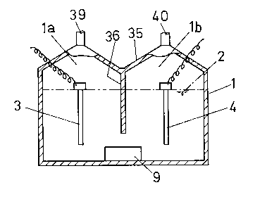
(EMBODIMENT 3)
In the embodiment shown in Fig. 6, the gases generated
by the water electrolysis are separated into a hydrogen gas
and an oxygen gas which are collected separately.
The electrolytic cell 1 contains a weak alkali water 2
(cont~;n;ng 0.1 % solution of tetramethyl ammonium
hydroxide). So that, the surface tension of the water is
reduced to facilitate the generation of the hydrogen gas and
oxygen gas. Electrodes 3, 4 are mounted within the
electrolytic cell 1.
A diaphragm 36 is mounted at the top of the
electrolytic cell 1 for separating the electrodes 3, 4, and
an ultrasonic wave generator 9 is mounted at the bottom of
the electrolytic cell 1. Outlet pipes 39, 40 for the
2 1 43482
hydrogen gas and oxygen gas are connected to the top wall 35
of the electrolytic cell 1 separated by the diaphragm 36.
In the embodiment being described, the ultrasonic wave
generator 9 is used to provide vibrations with which at
least one of the hydrogen molecule, oxygen molecule and
water molecule can produce resonance. Then, conducting
current through the electrodes 3, 4 cause the electrolytic
process to occur, producing a hydrogen gas and an oxygen gas
which may be collected into their respective upper spaces
la, lb within the electrolytic cell 1 and may then exit
through the outlet pipes 39, 40 which are connected to any
location where those gases are used. The ultrasonic waves
having 5,000 to 175,000 cycles per second may be used in
this embodiment.
An opaque diaphragm 36 may be used as the diaphragm
separating the center of the electrolytic cell 1.
Each of the electrodes 3, 4 may include an
electromagnet 37 mounted on the outside of the permanent
magnet 38 for placing the electrodes 3, 4 in the magnetic
field, as shown in Fig. 7.
It may be appreciated from the above that the
electrolytic liquid can more readily be decomposed by the
coupled action of the vibrations and magnetism, with less
current flow and with higher efficiency.
Industrial Applicability
41
21 43482
As the before described, the method and apparatus of
electrolyzing water according to the present invention are
useful for water electrolysis. According to the present
invention, water can be electrolyzed efficiently so that
hydrogen gas can be generated easily. The method and
apparatus according to the present invention may be used as
a multi-purpose energy generator source in a wide variety of
applications, such as automotive vehicles, power plants,
vessels, aircrafts, rockets and others which are propelled
by the energy.
42