Note: Descriptions are shown in the official language in which they were submitted.
` 2143505
BACKGROUND OF THE lN V~N'l'lON
1. Field of the Invention
This invention relates to an automotive window
retention system for motor vehicle windows which are fixed
(i.e., stationary) with respect to the vehicle body.
Specifically, the invention relates to an automotive window
retention system for mounting a window assembly onto a
recessed generally L-shaped peripheral flange of a window
aperture formed in an automotive vehicle body which employs
both hook and loop fabric fasteners and a curable adhesive
embedded therein to provide a very secure yet facile assembly
of the window to the vehicle body.
2. Description of the Prior Art
Various automotive window retention systems are well
known, one of which is represented in Fig. 1 of the drawings.
As shown therein, a fixed automotive window opening normally
consists of a metal interior body panel generally designated
10 welded to a metal exterior body panel generally designated
12, the latter of which has a peripherally recessed L-shaped
flange, generally designated 14, peripherally extending about
the desired automotive window opening. Flange 14 consists of
a lower leg 15 perpendicular to the exterior body panel 12 and
an upper leg 16 abutting an upper edge section 19 of the
interior body panel 10 and disposed generally normally to the
lower leg 15. Mounted on the lower leg 15 is one or more
rubber or plastic spacers 17 and mounted on the upper leg 16
is one or more rubber or plastic semispherical spacers 18
which serve to properly position and space the glass window 20
in the recessed body panel opening defined by the L-shaped
flange. A polyurethane adhesive is applied into the space
2143~5
between the upper leg 16 and the interior side of the window
glass panel 20 which, upon curing, serves to permanently
secure the window in the body panel opening.
An interior window trim 22 is secured to the
interior side of the interior body panel via Velcro~-type hook
and loop fabric fastening elements 23, 24, one of which is
secured to the interior trim 22 and the other of which is
secured to the interior side of the upper edge section 19 of
the interior body panel 10. An outer window trim 26 covers
the outer edge of the window 20 and a portion of the exterior
body panel 12 and is secured to the latter via a screw 27
extending through the exterior window trim 26 and the body
panel 12 properly positioned by a spacer 28.
As can be appreciated from the above description,
this prior art retention system requires numerous parts and
assembly steps, as a result of which it is quite costly in
terms of both actual material costs and in labor.
Furthermore, so far as is known, no presently available window
retention system is available which minimizes the mounting
materials used, saves steps and time, and allows for an easy
and facile mounting and retention of the window system in a
manner comparable to that according to the present invention.
SUMMARY OF THE lNvh~.lION
Accordingly, it is an object of the present
invention to provide a novel system for mounting stationary
motor vehicle window assemblies onto a flange within a window
aperture formed in a motor vehicle body which is relatively
simple in design, relatively inexpensive in material costs and
labor, and easy and facile to use and assemble.
-- 2
21~3505
~ It is a further object of the present invention to
provide an entirely new window assembly system including a
spacing system, a setting stop system and a retention system
for added outer and interior added window trim, which affords
motor vehicle window assemblies both a mechanical and adhesive
interlock system to provide a highly effective and permanent
mounting of the window to the flanged window aperture.
It is a more particular object of the present
invention to provide a combination device and adhesive joining
system with multifunctional functions, with direct and spin
off advantageous relationships, that have part of its design,
back up systems to make the entire system "idiot proof" to
apply, with fewer parts in comparison to the prior art, with
greater utility values in the continuous endeavor of
understanding that adhesives are less costly than nuts and
bolts, if applied in new joining systems that work with
adhesives.
Certain of the foregoing and related objects are
readily attained according to the present invention by the
provision of a retention system for an automotive window
assembly of the type having a window insertable onto a
recessed, generally L-shaped peripheral flange of a flanged
window aperture formed in an automotive vehicle body, the
window being adhesively secured to the peripheral flange. The
window assembly also includes an interior window trim member
for covering the interior side of the flange and an edge of
the window and an exterior window trim for covering the
exterior of the flanged window aperture and an edge of the
window. The system employs hook and loop type fabric
fastening means for securing the window to the flange, for
securing the interior trim to the interior side of the flange
` 2143505
and for securing the exterior trim member to the window and
exterior body panel. One of the hook and loop fabric
fastening means is adhesively bonded to the interior trim
window edge and exterior trim and the other of said hook and
loop fabric fastening means is joined to the interior and
exterior side of the L-shaped flange and at least one of the
window edge and the exterior body panel. Curable adhesive
means is embedded in the hook and loop fabric fastening means
which upon curing permanently joins the hook and loop fabric
fastening means together.
Preferably, the hook and loop fabric fasteners
having openings formed therein in which the curable adhesive
is received so that, upon curing, it forms a mechanical
interlock therewith. Most desirably, the curable adhesive is
a polyurethane adhesive. Most advantageously, the "other" of
the hook or loop fasteners is of a one-piece construction and
has an end panel section secured thereto by a line of
weakening and at least one web section to allow the same to be
reversed and be rotated 180 degrees for positioning against
the exterior edge of the window.
Certain of the foregoing and related objects
are readily attained in a retention system for an automotive
window assembly of the type having a window insertable onto a
recessed generally L-shaped peripheral flange of a flanged
window aperture formed in an aUtomotiVQ vehicle body, said
window to be adhesively secured to said peripheral flange.
The improvement comprises adhesive-backed, paired hook and
loop type fabric fastening means for securing said window to
said flange, said paired fastening means each having at least
one opening formed therethrough. One of said hook and loop
fabric fastening means is adhesively bonded to said window
-- 4
2143~05
edge and the other of said hook and loop fabric fastening
means is adhesively bonded to said exterior side of said L-
shaped flange. Curable adhesive means are also provided for
securing said window to said window flanged aperture in
cooperation with said hook and loop fabric fastening means,
said curable adhesive means being embedded in said hook and
loop fabric fastening means and which, upon curing,
permanently joins said hook and loop fabric fastening means
together. The curable adhesive means fills said holes in said
fastening means so that, upon curing, said adhesive means
forms a mechanical interlock with said fastening means.
BRIEF DESCRIPTION OF THE DRAWINGS
These and other objects and features of the present
invention will become apparent from the following description
considered in connection with the accompanying drawings which
discloses several embodiments of the present invention. It is
to be understood that the drawings are to be used for the
purpose of illustration only and not as a definition of the
limits of the invention.
In the drawings, wherein similar reference numerals
denote similar elements throughout the several views:
FIG. 1 is a side sectional view of the window
retention system of the prior art;
FIG. 2 is a side sectional view comparable to
that of FIG. 1 but showing the window retention system of the
present invention;
2143~05
~ FIG. 3 is a perspective view of the hook fabric
web employed in the present retention assembly;
FIG. 4 is a schematic cross sectional view
showing the three main retention points provided by the
present retention system; and
FIG. 5 is a view of the hook fabric web shown in
FIG. 3 but showing the lower panel thereof twisted and
reversed 180 degrees to modify its point of application.
DETAILED DESCRIPTION OF THE PREFERRED EMBODIMENT
Referring now in detail to the drawlngs, as
previously discussed, FIG. 1 illustrates the prior art window
retention system as heretobefore described. FIGS. 2-5
illustrate the inventive window retention system according to
the present invention which specifically eliminates the need
for the use of screw fasteners or spacers as shown in the
prior art represented in FIG. 1.
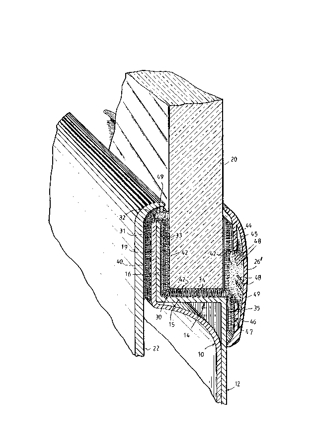
In particular, and as shown in FIGS. 2 and 3, a
multi-folded, adhesive-backed web of Velcro~ hook fabric
fastening members generally designated 30 is received over the
interior body panel 10, the L-shaped recess peripheral flange
14 and a portion of the exterior body panel 12. Web 30
includes a generally upright first body panel 31 which is
adhesively secured via its rear side to the upstanding section
or leg l9 of the rear interior body panel 10, a second body
panel 32 disposed normally thereto, which is adhesively
secured to the top edge of the upstanding legs 19, 16 of the
rear body panel 10 and of the L-shaped flange 14, a third
upstanding body panel 33 adhesively joined to the exterior
-- 6 --
214~05
surface of the upper leg 16 of the L-shaped flange 14, a
generally horizontally disposed fourth body panel 34 secured
to the exterior of the lower leg 15 of the recessed L-shaped
flange 14, and a generally upright, but downwardly depending
fifth body panel 35 which is adhesively joined to the exterior
body panel 12. Each of the body panels 31, 33, 34, 35 and 36
have one or more holes or apertures 36 formed therethrough,
the purpose of which will be discussed in greater detail
hereinafter.
To mate with the hook fabric body panels 31, 32, 33,
34, 35 of web 30, the corresponding Velcro~ loop fabric
fastening elements are attached to the other window assembly
parts opposite the hook fabric body panels where needed. In
particular, an adhesive backed Velcro~ web 40 of loop-type
fastening elements is secured to the interior window trim 22
to permit attachment of the latter to the interior surface of
the upper leg 19 of interior body panel 10 via its mechanical
interlock with hook body panel 31. Similarly, loop fabric web
42 is folded in the form of a U and attached via its adhesive
backing to the peripheral lateral and bottom edges of the
window glass 20. The window glass 20 is then positioned in
the window aperture in its desired position, and it is pressed
against hook-like fastening elements of body panels 33 and 34
to mechanically lock the same in place The outside leg of
the U-shaped web 42 is intended for mating with a hook-type
Velcro~ web 44 applied to the interior side of exterior trim
cap 26' along its top interior flange 45. Similarly, the
interior lower portion of the exterior window cap 26' is
attached to the lower body panel 35 via a loop web 46
adhesively attached to its bottom interior flange 47, thereby
providing a mechanical interlock with hook fabric panel 35.
214350~
;
`~ Prior to the mounting as described above, a
conventional polyurethane adhesive 49 would be embedded in the
hook and loop fasteners of the various Velcro~ webs so that,
upon curing, the mechanical interlocking hook and loop
fasteners would be permanently embedded within the adhesive
and locked in place, thereby securely retaining the window
within the aperture in the mounting position shown. As
further shown, the exterior window cap has an upper and lower
pair of angled flanges 48 which also would be embedded in the
urethane adhesive to further facilitate interlocking of the
exterior window trim 26' to the window 20 and exterior body
panel 12.
As schematically represented in FIG. 4, this
retention system provides three ways of locking the parts
together. In the first part (arrow 1), the hook and loop
fasteners 50, 51 are adhesively bonded to their respective
window trim or body panel parts 52, 53 via an adhesive backing
and together via their mechanical interlocking. In the second
part (arrow 2), the adhesive is embedded within the mechanical
hook and loop fasteners to provide a permanent retention of
the fasteners together. Third, as shown by arrow 3, the holes
36 in the hook and loop fastener webs allows the adhesive to
pass therethrough, thereby providing a mechanical interlock
between the openings of opposing hook and loop web panels.
This three-part adhesive and mechanical interlock system
affords a retention redundancy which insures a very permanent
and stable fixed mounting of the window to the flanged body
panel opening while affording an extremely simple and labor-
saving mounting technique.
Finally, FIG. 5 shows the web 30 of FIG. 3 but with
the lower panel 36 reversed and rotated 180 degrees via its
- - 2143~
perforated line of weakening 38 such that it is only retained
by a thin web 39. As a result of this orientation, a complete
U-shaped loop web 42 would not be necessary for the window
edge and, instead, an L-shaped piece (not shown) could be used
for securing it to the L-shaped flange 14 via hook body panels
33, 34. In this embodiment, the lower body panel 36 would
then be attached to the window edge for securing the same to
the exterior window trim, as desired, for certain
applications.
Various modifications of the present invention can
be made as will be apparent to those skilled in the art. For
example, the hook and loop fasteners of the various web panels
can, of course, be reversed depending upon the desired
application. In addition, the interior and exterior window
trims can, of course, be modified to suit the particular
application, as well. Other conventional, curable adhesives
besides polyurethane could also be employed.
Accordingly, while only several embodiments of the
present invention has been shown and described, it is to be
understood that many changes and modifications may be made
thereunto without departing from the spirit and scope of the
invention as disclosed herein.