Language selection

Search

Patent 2143550 Summary

Third-party information liability

Some of the information on this Web page has been provided by external sources. The Government of Canada is not responsible for the accuracy, reliability or currency of the information supplied by external sources. Users wishing to rely upon this information should consult directly with the source of the information. Content provided by external sources is not subject to official languages, privacy and accessibility requirements.

Claims and Abstract availability

Any discrepancies in the text and image of the Claims and Abstract are due to differing posting times. Text of the Claims and Abstract are posted:

  • At the time the application is open to public inspection;
  • At the time of issue of the patent (grant).
(12) Patent Application: (11) CA 2143550
(54) English Title: SLAT STRUCTURE FOR VENETIAN BLIND
(54) French Title: LAME POUR STORES VENITIENS
Status: Deemed Abandoned and Beyond the Period of Reinstatement - Pending Response to Notice of Disregarded Communication
Bibliographic Data
Abstracts

English Abstract


The present invention is a slat structure for Venetian
blind, comprising a head rail, a bottom rail, an adjustment
rod, a lift cord, a plurality of ladder tapes and several
slats. The hole for the lift cord to feed through is provided
in a round shape and its position is closer to the rear edge
of the slat. When the slats are in closed position, the lift
cord hole will be blocked by the next slat, preventing the
sunlight coming from that hole and improving the privacy
inside the room.


Claims

Note: Claims are shown in the official language in which they were submitted.

WHAT IS CLAIMED IS:
1. A structure of the slat used in a Venetian blind
comprising a head rail, a bottom rail, an adjustment rod, a
lift cord, a plurality of ladder tapes and several slats,
characterized in that:
the two ends of each slat are respectively provided with
a lift cord hole, which is a round-shaped hole and is provided
closer to the rear edge of the slat, when the slats are in a
closed position, the lift cord hole will be blocked by the
next slat, preventing the sunlight coming from that hole into
the room.

Description

Note: Descriptions are shown in the official language in which they were submitted.


~ 5~0
A ~IAT ~Lr~u~:luKE FOR VENETIAN BLIND
3ACRGROUND OF TE~E l~v~~
(a) Field of the Invention
The present invention relates to the atructure of the
slat used in a Venetian blind, particularly to an improve
structure of the slat which can completely block out the sun
light and assure the privacy inside the room.
(b) Description of the Prior Art
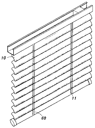
Please refer to FIG. 1 which shows a perspective view of
the most commonly seen Venetian blind available these days.
The structure consists of a head rail 40, a bottom rail 50,
an adjustment rod 30, a lift cord ~o, a plurality of ladder
tapes 60 and several slats 10.
The head rail 40 is used to secure the entire Venetian
blind structure on the window or door, the ~ottom rail 50 is
used as a dead weight 80 that the slats 10 can drop down
easily, the ad]ustment rod 30 can be turned to cooperate with
the ladder tapes 40 for adjusting the angle of opening of the
slats so that the ; n(~nml n~ sunlight can be controlled.
The two ends of each of the slat 10 are provided with a

~35~0
hole 11 for the lift cord 20 to feed through. Thus the lift
cord 20 can be used to pull the plurality of the slats 10
upward or downward.
In order to allow the adjustment of the slats 1~ at any
angle, the hole 11 is fabricated into an elongated shape.
Thus, when the adjustment rod 30 is turned, the slats 10 are
also turned by the ladder tapes 60, this does not cause any
interference to the lift cord 20. E~owever, there is a majar
drawback with this structure. When a user tries to turn the
slats 10 downward 80 as to block out the sunlight or assure
his privacy, the lower slat 10 cannot provide the blocking of
the upper elongated-shaped hole 11. Therefore, sunlight will
shine into the room through the hole 11, and privacy is not
assured.
Sl~MMARY OF THE lNV~~
The main object according to the present invention is to
provide a structure for the slat o~ the Venetian blind which
can co npletely block out the sunlight and improve the privacy
ins ide the room .
BRI3F DESCRIPTION OF TH3 DRAWINGS
The drawings disclose an illustrative embodiment of the
present invention which serves to exemplify the various

~1 ~3~50
advantages and objects hereof, and are as follows:
FIG. 1 is a perspective view of the structure of a
convPnt;~nAl Venetian blind.
FIG. 2 i8 a perspective view looking from the back of the
mini blind according to the present invention.
FIG. 3 is another view of F~G. 2, with the head rail
removed.
DETAILED DESCRIPTION OF THE ~Kr;r riKRril/ EMBODIMENT
~eferring to FIG. 2, which i8 a perspective view looking
from the back of the Venetian blind of the present invention.
When the adjustment rod 30 is turned to the end, the slat 10
are in a corllpletely closed position. At this time, the slat
in the lower position can block out the sunlight coming fro~
the upper hole 11 of the slat 10. The privacy inside the room
is also assured.
Referring to FIG. 3, which is a view of FIG. 2 with the
head rail removed. The structure of the present invention is
pretty much similar to the con~Pn~ nAl structure. The
difference is on the location of the lift cord hole ll, which
is changed to a round shape and is provided closer to the rear
edge. When the slats 10 are in a closed poAition, the

fi~ ` 2 ~ '5 B
sunlight coming from the hole 11 can be blocked out by the
next slat 10, thereore, the sunlight will not be able to
enter into the room through that hole.
Many changes and modii~ications in the above described
embodiment o~ the invention can, of course, be carried out
without departing ~rom the scope thereo~. Accordingly, to
promote the progress in science and the use~ul arts, the
invention is disclosed and is intended to-be limited only by
the scope o~ the appended cIaims.

Representative Drawing
A single figure which represents the drawing illustrating the invention.
Administrative Status

2024-08-01:As part of the Next Generation Patents (NGP) transition, the Canadian Patents Database (CPD) now contains a more detailed Event History, which replicates the Event Log of our new back-office solution.

Please note that "Inactive:" events refers to events no longer in use in our new back-office solution.

For a clearer understanding of the status of the application/patent presented on this page, the site Disclaimer , as well as the definitions for Patent , Event History , Maintenance Fee  and Payment History  should be consulted.

Event History

Description Date
Time Limit for Reversal Expired 1998-03-02
Application Not Reinstated by Deadline 1998-03-02
Deemed Abandoned - Failure to Respond to Maintenance Fee Notice 1997-02-28
Application Published (Open to Public Inspection) 1996-08-29
All Requirements for Examination Determined Compliant 1995-02-28
Request for Examination Requirements Determined Compliant 1995-02-28

Abandonment History

Abandonment Date Reason Reinstatement Date
1997-02-28
Owners on Record

Note: Records showing the ownership history in alphabetical order.

Current Owners on Record
HENRY LIN
Past Owners on Record
None
Past Owners that do not appear in the "Owners on Record" listing will appear in other documentation within the application.
Documents

To view selected files, please enter reCAPTCHA code :


To view images, click a link in the Document Description column. To download the documents, select one or more checkboxes in the first column and then click the "Download Selected in PDF format (Zip Archive)" or the "Download Selected as Single PDF" button.

List of published and non-published patent-specific documents on the CPD .

If you have any difficulty accessing content, you can call the Client Service Centre at 1-866-997-1936 or send them an e-mail at CIPO Client Service Centre.


Document
Description 
Date
(yyyy-mm-dd) 
Number of pages   Size of Image (KB) 
Abstract 1996-08-28 1 15
Description 1996-08-28 4 96
Claims 1996-08-28 1 14
Drawings 1996-08-28 3 139
Representative drawing 1999-08-03 1 37
Examiner Requisition 1997-03-17 2 87
Courtesy - Office Letter 1997-04-02 1 71