Language selection

Search

Patent 2143724 Summary

Third-party information liability

Some of the information on this Web page has been provided by external sources. The Government of Canada is not responsible for the accuracy, reliability or currency of the information supplied by external sources. Users wishing to rely upon this information should consult directly with the source of the information. Content provided by external sources is not subject to official languages, privacy and accessibility requirements.

Claims and Abstract availability

Any discrepancies in the text and image of the Claims and Abstract are due to differing posting times. Text of the Claims and Abstract are posted:

  • At the time the application is open to public inspection;
  • At the time of issue of the patent (grant).
(12) Patent Application: (11) CA 2143724
(54) English Title: MULTI-T
(54) French Title: MULTI-T
Status: Deemed Abandoned and Beyond the Period of Reinstatement - Pending Response to Notice of Disregarded Communication
Bibliographic Data
Abstracts

English Abstract


The present invention is used to hold sheetrock in an
elevated position, while it is being secured. This device
has an upper horizontal tubing platform T that comes in
contact with the sheetrock. This platform is covered
with a foam rubber to protect and secure the sheetrock.
The lower verticle tubing comes in contact with the
floor. Where the tubing meets the floor, a rubber boot
is secured. The cupling under the boot is adjustable to
make up the difference in the holes in the middle tubing
if needed. This unit is telescopic in the way that one
tube slides over the other as it goes through a selection
of holes, which choses the height of the ceiling. Also
this device comes apart below the two upper support
braces. By backing off the handle attachment you now
have an extension handle. Also this extension handle
comes apart at screw safety lock nut. Now you have two
single handles. Attachments can be used on these exten-
sion handles to do various other jobs such as, painting
sanding, and washing windows etc. This device is a MULTI
use tool,and it can be easily disassembled and stored
away for further use.


Claims

Note: Claims are shown in the official language in which they were submitted.

Claims
The embodiments of the invention in which an ex-
clusive property or privilege is claimed are defined as
follows:"
Claim (1) This is a device that will hold up sheetrock
while it is being secured to the ceiling.
There is an upper horizontal platform T that
is padded with foam rubber to protect the
sheetrock as well as keeping it from moving
around. This pad is secured with adhesive
glue.
Claim (2) The device that is defined in claim (1) is
telescopic. The middle tube moves up and down
over the lower tube. Because it is telescopic
you can chose different heights for different
ceilings. While holding the lower tube press
in the spring button and turn the middle
section outer tube slightly. Now the spring
button is riding in between the middle section
outer tube and the lower tube. When desired
height of ceiling is reached line up arrows
that are marked on middle and lower tubing,
while holding the device at a slight angle.
Now let the button go into the nearest hole
while straighten up the device vertically to
hold tension on the sheetrock. Now one end of
the sheetrock is secured for nailing.

Claim (3) This floor engaging part of the device is tel-
escopic. A rubber boot is glued to the cupling.
The cupling is threaded and it screws over the
inner lower tubing which is also threaded. This
telescopic boot will make up the difference
between the holes in the middle tubing.
Claim (4) Now referring to claim (1) the upper horizon-
tal platform T is strategicly electric welded
in five places to strengthen the support syst-
em.
Claim (5) The temporary support device used in enstall-
ing sheetrock to the ceiling, as in claim (2)
has a dual purpose which is one long extension
handle or two short extension handles. The
extension handle comes apart at the top of the
middle tubing, which is the handle attachment
nut. As exclaimed in claim (2), the extension
handle can go through a series of heights by
depressing the spring button. The extension
handle also comes apart at the screw safety
lock nut to make two shorter extension hand-
les by pressing in the spring button and
turning the lower inner tubing slightly and
pulling downward by backing off the safety
lock nut.
When your job is completed, Your MULTI-T
device can be disassembled and put away for
further use.

Description

Note: Descriptions are shown in the official language in which they were submitted.


21 ~3724
Backqround Of Invention
Field Of Invention
This invention relates to a manually operated device that
holds sheetrock to the ceiling while it is being installed.
Description Of Prior Art
Sheetrock installation is a job requiring more then one
person. A wooden T is a device that many have used in the past and
are still using today. This was made of two pieces of wood nailed
together. One long vertical piece meets the shorter horizontal one
in the center. This device damaged the sheetrock as well it is
very awkward to use and trying to acquire the right height seemed
like an endless chore.
Also there is a floor jack device for holding up sheetrock.
The device is very complicated to operate, plus big and bulky. The
price is very expensive and beyond the means of the average
person.
There are some devices on the market similar to mine, but
they are complicated, bulky, and expensive.
Summary Of Invention
I have found that my invention has overcome the disadvant-
ages of the prior art.
My invention is very lightweight, but yet strong enough to
hold heavy sheetrock. It is also inexpensive to manufacture. The
device is easy to handle, plus you won't need a course to operate
it. This device is not a dead item. When your ceiling is completed
the device can be changed into an extension handle by separating
the device below the upper platform braces. Now you can use this
extension handle for painting, sanding, and cleaning windows etc.

21 43724
Brief Description Of Drawinqs
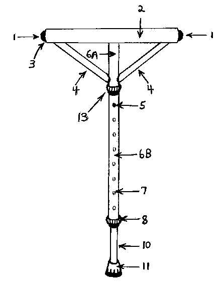
Fig. (1) It is an elevated sketch of the sheetrock device in
accordance to the invention.
ig. (2) Is a sectional partially exploded view of the upper
portion of Fig. (1).
ig. (3) Is a vertical sectional view of the middle section,
which is the upper section of extension handle.
ig. (4) Is a vertical section view of lower sections of the
device
Description of The Preferred Embodiment
Referring to Fig. (1), A device for holding sheetrock to
the ceiling in accordance with the invention. It includes a
horizontal tubing platform T (3) that comes in contact with
the sheetrock, and is connected to an outer tube (6a) and
inner tube (10). These tubes are vertical and telescopic in
nature. The inner tube (10) is connected to the rubber boot (11).
This rubber boot (11) comes in contact with the floor.
Referring to Fig. (2), Comprises of horizontal tubing
platform T (3) that comes in contact with sheetrock as shown in
Fig. (1). This is covered with sponge rubber (2) which runs from
end to end on the upper horizontal platform T (3). In the upper
horizontal platform T (3) there are inserted plastic plugs (1) in
each end. Also there are welded upper support braces (4) running
at a 45 degree angle from vertical tubing (6a) to end of vertical
tubing (6a), just below upper support braces (4), opposite end to
horizontal T (3) is welded inside outermost tubing (6a) an extra
course thread nut (14) to accommodate threaded stock (15) which is
upper end of extension handle.

21 43724
-
Referring to Fig. (3), Comprises of middle section (6b) and
is also the upper view of the extension handle as mentioned in
Fig. (2). In the middle section tubing (6b) are holes (7) drilled
at same intervals running vertically from below handle attachment
nut (13) to above screw safety lock nut (8). By pressing spring
button (5) the device will manually travel up or down vertically,
as you chose the hole (7) to the desired height of the ceiling
which is 7 to 10'. The upper view of the extension handle or
upper middle section (6b) consists of threaded stock (15) welded
into middle section tubing (6b). The handle attachment nut (13) is
slipped over threaded stock (15) so it does not cover any of the
threaded stock (15). Then set screw (8) is tightened into handle
nut (13) to secure it. Lower end of middle section (6b) running
vertically is threaded (9) to take screw safety lock nut (8).
Referring to Fig. (4), Is a vertical sectional view of lower
section which was mentioned in Fig. (3). It consists of a vertical
piece of tubing (10) which fits inside middle tubing (6b) in a
telescopic way as told in Fig. (1) The upper part of tubing (10)
has a hole (20) drilled in it. Spring button (5) with a hole
drilled in one end of it has a shoulder on it. The spring (19) is
set in the hole of the spring button (5). then set the spring (19)
which is set in the hole of the spring button (5) down the upper
part of tubing (10) till the spring button (5) goes into the hole
(20) so as the spring (19) runs Horizontally to let the button
come out through the hole (20). There by the shoulder on the
button (5) will not let the button (5) come out through the hole
(20). This spring button (5) goes out through the holes (7) in the
middle section (6b) as in Fig. (3) to make the device telescopic.
The lower part of tubing (10) is threaded (16) so it could take a
cupling (17). This adjusting boot (11) makes up the difference
between the holes (7) in the middle section (6b). Extra course
threaded stock (21) is welded into end of lower section tube (10)
opposition end to rubber boot (11).

Representative Drawing
A single figure which represents the drawing illustrating the invention.
Administrative Status

2024-08-01:As part of the Next Generation Patents (NGP) transition, the Canadian Patents Database (CPD) now contains a more detailed Event History, which replicates the Event Log of our new back-office solution.

Please note that "Inactive:" events refers to events no longer in use in our new back-office solution.

For a clearer understanding of the status of the application/patent presented on this page, the site Disclaimer , as well as the definitions for Patent , Event History , Maintenance Fee  and Payment History  should be consulted.

Event History

Description Date
Inactive: IPC from MCD 2006-03-11
Time Limit for Reversal Expired 1999-03-01
Application Not Reinstated by Deadline 1999-03-01
Deemed Abandoned - Failure to Respond to Maintenance Fee Notice 1998-03-02
Application Published (Open to Public Inspection) 1996-09-02

Abandonment History

Abandonment Date Reason Reinstatement Date
1998-03-02
Owners on Record

Note: Records showing the ownership history in alphabetical order.

Current Owners on Record
CHARLES LLOYD JESSOME
Past Owners on Record
None
Past Owners that do not appear in the "Owners on Record" listing will appear in other documentation within the application.
Documents

To view selected files, please enter reCAPTCHA code :


To view images, click a link in the Document Description column (Temporarily unavailable). To download the documents, select one or more checkboxes in the first column and then click the "Download Selected in PDF format (Zip Archive)" or the "Download Selected as Single PDF" button.

List of published and non-published patent-specific documents on the CPD .

If you have any difficulty accessing content, you can call the Client Service Centre at 1-866-997-1936 or send them an e-mail at CIPO Client Service Centre.

({010=All Documents, 020=As Filed, 030=As Open to Public Inspection, 040=At Issuance, 050=Examination, 060=Incoming Correspondence, 070=Miscellaneous, 080=Outgoing Correspondence, 090=Payment})


Document
Description 
Date
(yyyy-mm-dd) 
Number of pages   Size of Image (KB) 
Claims 1996-09-01 2 55
Drawings 1996-09-01 4 42
Abstract 1996-09-01 1 27
Description 1996-09-01 3 120
Representative drawing 1999-08-03 1 7
Notice: Maintenance Fee Reminder 1997-12-01 1 119
Courtesy - Abandonment Letter (Maintenance Fee) 1998-03-29 1 187
Notice: Maintenance Fee Reminder 1998-12-01 1 118
Fees 1997-03-02 1 65
Courtesy - Office Letter 1995-03-29 2 57