Note: Descriptions are shown in the official language in which they were submitted.
2143804
Case 215
MTT.~ FOa~MTNG nRVT~'-R
B~ckgro-7nd
The present invention relates to milk foaming devices
and a dispensing assembly for use with a milk foaming
device.
People all over the world enjoy coffee beverages and
are increasingly demanding the "classic" coffee beverages
made with espresso. Espresso is the essence of the coffee
bean which many fanciers of coffee believe gives the
richest, most complex flavor of the beverage. The "classic"
espresso beverages include such beverages as caffé latte,
cappuccino, and espresso macchiato. These "classic"
espresso-type beverages use one or more shots of espresso in
combination with steamed milk, a quantity of foamed milk, or
both. For example, the caffé latte uses one shot of
espresso with a volume of steamed milk topped off with
foamed milk. The cappuccino uses the foamed milk as a
2143804
-
primary ingredient with the addition of a smaller volume of
steamed milk and a shot of espresso. The espresso macchiato
uses a single shot of espresso with a dollop of foamed milk
as garnish or as a flavor and heat-retaining cap.
As can be seen from above, the steaming and especially
the foaming of milk is essential to these popular "classic"
espresso drinks. The milk is critical because it provides
flavor, texture, as well as garnish for these espresso
drinks. Additionally, foamed milk is used in other
beverages such as steamed or hot cocoa, "steamers" combining
steamed milk and a flavoring syrup, as well as any other
application where the flavor, texture and garnishing effect
of foamed milk is desired.
Prior art milk foaming techniques involved the time
consuming and highly skilled ability to steam a pitcher of
milk to produce milk foam having a desired loft and
consistency. Milk is foamed at an espresso machine by a
barista who operates the espresso machine. The espresso
machines includes a steam wand connected to a steam source
in the machine to provide steam in order to steam milk to
produce milk foam. Because the prior art milk steaming
techniques require manual steaming and human judgment, they
required a level of skill only acquired through teaching and
apprenticeship. Additionally, the foaming of milk requires
a considerable amount of time in order to bring chilled milk
up to a temperature of approximately 170F and the proper
placement and repositioning of a steam nozzle.
In view of the increasing popularity of espresso
drinks, as well as the desire to produce products more
consistently and economically, automatic milk foam
dispensers have been created. Examples of prior art milk
foam dispensers are shown generally in U.S. Patent
No. 4,779,519 to Giuliano and U.S. Patent No. 4,71S,274 to
Paoletti. These automatic milk foaming devices combine
2143804
~r _
steam, air and milk in a swirl chamber to produce foamed
milk. Both the Giuliano and Paoletti devices dispense
foamed milk from the swirl chamber through an opening in the
bottom thereof. Both devices also include a baffle or
partition positioned in the swirl chamber to slow down the
swirling of the foamed milk. These prior art devices help
reduce the skill required to operate a milk foaming device,
make it more economical since only a needed quantity of milk
is used instead of heating a whole pitcher, increase the
consistency of the foamed milk produced by these devices,
and increase the speed at which the foamed milk can be
faster since the time needed to heat up a pitcher of milk is
not required.
Additional characteristics that are important to
serving foamed milk in coffee beverages or other
applications, is the presentation, sanitation and ease of
cleanup. Presentation is important since it is desirable to
dispense foamed milk into the selected container without
overfilling or spraying the container. This is important to
sanitation in that each cup of beverage need not be wiped
and the milk foamer can be easily cleaned. The easiest milk
foaming device to maintain is one that generally is the more
sanitary device.
The prior art automatic milk foaming devices generally
have problems with presentation, sanitation and cleanup.
The devices as shown in Giuliano and Paoletti tend to
splatter or spray the foamed milk foam out of the swirl
chamber. The splattering of milk is a presentation problem
since the milk may foam over on the cup or saucer requiring
cleanup of each serving. The splattering problem also
creates a sanitation problem in that the beverage serving
requires additional handling in order to cleanup the
splattered milk. Another sanitation problem is created by
the splattering of the milk on the outside of the dispensing
device. As the milk is very hot it tends to crust on the
214380~
outside making cleanup difficult. Efficiency is adversely
affected as a result of the prior art presentation,
sanitation and cleanup problems. Efficiency is affected
since time is required to remove the splattered milk from
the beverage serving as well as cleaning up the dispensing
device.
Therefore, it would be desirable to provide an
automatic milk foaming device which dispenses foamed milk
into a container without splattering. Such a device would
prevent the presentation, sanitation and cleanup problems
discussed hereinabove. Such a device would also increase
the efficiency of an operation employing foamed milk in its
food service products.
214380~
Objects and Summary
A general object of the present invention is to provide
a milk foaming device which prevents foamed milk from
spraying or splattering when dispensed from the automatic
milk foaming device.
Briefly, and in accordance with the foregoing, the
present invention envisions a milk foaming device for
emulsifying steam, milk and air to produce foamed milk. The
milk foaming device includes an ingredient combining
assembly for combining the steam, milk and air connected to
a swirl chamber for blending the ingredients. A discharge
tube is attached to the swirl chamber for dispensing foamed
milk therethrough. A concave notch is formed in the wall of
the discharge extending from a dispensing port of the tube
upwardly along the walls. The notch retards or prevents
formation of bubble surfaces over the dispensing port of the
discharge tube and thereby prevent splattering of milk. A
laminator is provided in the tube for inducing a columnar
flow of foamed milk from the discharge tube.
2143804
Brief Description of the Drawings
The organization and manner of the structure and
operation of the invention, together with further objects
and advantages thereof, may be understood by reference to
the following description taken in connection with the
accompanying drawings, wherein like reference numerals
identify like elements, and in which:
FIG. 1 is a perspective partial fragmentary view of a
portion of an espresso machine including an automatic milk
foaming device of the present invention attached thereto;
FIG. 2 is an exploded perspective view of the milk
foaming device as shown in FIG. 1;
FIG. 3 is an enlarged partial fragmentary elevational
view of the discharge tube taken along line 3-3 in FIG. 2
showing a laminator retained in a dispensing tube associated
with the milk foaming device; and
FIG. 4 is a partial fragmentary cross-sectional view of
the discharge tube taken along line 4-4 in FIG. 3.
2143804
-
Detailed Descript;on of the Preferred ~mbodiment
While the invention may be susceptible to embodiment in
different forms, there is shown in the drawings, and herein
will be described in detail, an embodiment with the
understanding that the present description is to be
considered an exemplification of the principles of the
invention and is not intended to limit the invention to that
as illustrated and described herein.
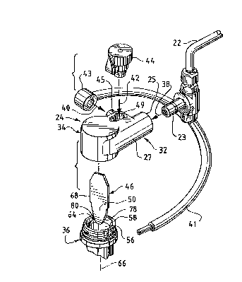
FIG. 1 shows a portion of an espresso machine 20 for
making espresso beverages. The espresso machine includes a
steam wand 22 extending therefrom and providing a source of
steam. A milk foaming device 24 is attached to the steam
wand 22 to produce foamed milk by emulsifying steam, air,
and milk. A container 26 is positioned below the milk
foaming device to receive a quantity of foamed milk
discharged from the device 24. The milk foaming device 24
of the present invention controllably dispenses a quantity
of foamed milk into the container 26 without splattering
milk on the housing 28 of the espresso machine 20, the
container 26 or the counter area 30 surrounding the espresso
machine 20. As such the milk foaming device 24 of the
present invention improves the presentation of the dispensed
milk foam, the sanitation of the foam producing operation,
and the cleanup of the device 24.
The milk foaming device 24 of the present invention
includes an ingredient combining assembly 32, an emulsion
chamber or swirl chamber 34 and a discharge tube 36. With
further reference to FIG. 2, the ingredients combining
assembly 32 includes a steam path (as represented by arrow
38), a milk path (as represented by arrow 40), and air path
(as represented by arrow 42). The steam path 38 includes
the steam wand 22 which delivers steam through fitting 23
inserted into an inlet end 25 of a housing 27 of the device
24. The milk path 40 extends from a milk reservoir (not
214~804
shown) through tube 41 having end fitting 43 connected with
inlet 45 of the ingredients combining assembly 32 where it
is mixed with steam and air. The air path 42 includes an
air flow regulator 44 inserted into air inlet 49 in the
housing 27 to control the amount of air which is combined
with the steam and milk. The housing 27 includes internal
means providing a venturi action powered by the steam jet
for drawing in the milk and air. The venturi means may be
similar to that disclosed in either of the above prior art
patents or of any other known construction.
The ingredients are combined in the ingredient
combining assembly 32 and are injected into the swirl
chamber 34. The swirl chamber 34 is a hollow generally
cylindrical body in which the ingredients are blended. The
blended ingredients swirl downwardly from the swirl chamber
34 into the discharge tube 36. As will be discussed in
greater detail hereinbelow, a laminator 46 is positioned in
the discharge tube 36 for directing the foamed milk
downwardly out of the discharge tube 36. Foamed milk
discharged from the milk foaming device 24 is directed into
the container 26.
FIGS. 2 and 4 provide views of a dispensing assembly 48
of the present invention. The dispensing assembly 48
includes the dispensing tube 36 and the laminator 46. As
can be seen in FIG. 4, the laminator 46 has a blade
structure defining a pair of surfaces 50, 52 which face in
opposite directions. The discharge tube 36 has a wall 54
forming a generally tubular shape defining a lumen 56. An
upper end of the lumen 56, communicating with the swirl
chamber 34, defines a receiving port 58. An end of the
lumen 56 distal the receiving port 58 defines a discharge
port 60. Milk flowing from the swirl chamber 34 to the
discharge tube 36 passes through the receiving port 58.
After traveling through the lumen 56 the foamed milk is
21~380~
.
directed from the discharge tube 36 through the discharge
port 60.
In prior art milk foaming devices, bubble surfaces form
over the discharge port 60 as foamed milk is being dispensed
through the dispensing assembly 48. As the bubble surface
grows, foamed milk builds up behind the bubble surface.
Eventually, the force of the foamed milk behind the bubble
surface overcomes the surface tension of the bubble surface
at which point the bubble surface breaks. The foamed milk
which builds up behind the bubble surface splatters from the
device resulting in a splattering effect on the container,
the espresso machine, and the surrounding surface.
The milk foaming device 24 of the present invention
eliminates the splattering produced by the prior art
devices, by interrupting the peripheral wall of the
discharge tube so that it has a non-circular and axially
variable or notched discharge end or edge. In the
embodiment shown, this is achieved by including at least one
concave notch 62 being formed through the wall 54 of the
discharge tube 36. The concave notch 62 prevents or retards
the formation of a bubble surface over the discharge port
60. In an alternate embodiment, a pair of concave notches
62 are provided at opposite sides of the tube. For example,
the notch 62 in FIG. 4 would have a mirror image identical
notch formed on the opposite side of the discharge tube 36.
By eliminating the formation of a bubble surface over the
discharge port 60, the present invention overcomes the
undesirable effects of the prior art splattering problems.
Elimination of splattering milk eliminates the time and
effort required to clean up a container before presenting it
to a customer, as well as, improves cleanup and sanitation.
Additional details regarding the structure and function
of the dispensing assembly 48 is illustrated in a
perspective view in FIG. 2, a planar elevational view in
21~3801
5 FIG. 3, and a side elevational view in FIG. 4. As shown in
FIGS . 2 and 4, the discharge tube 36 is provided with a
channel 64 for holding the laminator 46 in the lumen 56 of
the discharge tube 36. During assembly, the laminator 4 6 is
inserted into the lumen 56 along the central axis 66. The
channel 64 is sized and dimensioned approximately equal to
or slightly smaller than an edge 68 of the laminator 46
which is engaged with the channel 64. The laminator 46
retained in the channel 64 divides the lumen 56 into first
and second chambers 70, 72. One chamber 70, has the concave
15 notch 62 formed through the wall 54 generally opposite a
corresponding plane 50 of the laminator 46. As such, the
concave notch 62 associated with the chamber 70 prevents the
formation of a bubble surface over the corresponding portion
of the discharge port 60.
As shown in FIGS. 3 and 4, the laminator 46 positioned
in the discharge tube 36 is generally symmetrically
positioned relative to the discharge port 60. Each of the
planar surfaces 50, 52 forms one of the surfaces of
a corresponding chamber 70, 72. A tip end 74 of the
25 laminator 46 extends beyond the discharge port 60.
Additionally, distal edges 68, 76 of the laminator 46 have
inwardly sloped sections 78, 80 which slope towards the
central axis 66 terminating at a pointed but blunt, tipped
end 82. The sloped sections 78, 80 promote the focusing of
30 the flow of foamed milk from the discharge tube towards the
blunt end 82. The blunt end 82 is formed generally
perpendicular to the central axis 66.
In use, the milk foaming device 24 of the present
invention is attached to a steam wand 22 of an espresso
35 machine 20. The device 24 is operated to dispense a
quantity of foamed milk into a container 26. The device 24
includes the dispensing assembly 48 including the laminator
46 retained in the lumen 56 of the dispensing tube 36.
Milk, steam, and air are combined in the combining assembly
21~3804
.
S 32 and swirled in the swirl chamber 34. The swirled or
blended ingredients pass from the swirl chamber 34 into the
dispensing assembly 48 through the receiving port 58.
Once in the dispensing tube 36, the foamed milk passes
through the chambers 70, 72 of the lumen 56 between an
inside surface 84 of the walls 54 in a corresponding planar
surface 50, 52 of the laminator 46. Foamed milk tends to be
pulled inwardly (as indicated by arrows 86) along the planes
50, 52 of the laminator 46. Foamed milk traveling towards
the discharge port 60 is prevented from forming a bubble
surface due to the interruption or concave notch 62 formed
in the wall 54 of the discharge port 60. Milk flows
downwardly out of the tube and along the planar surfaces 50,
52 and is directed inwardly (as indicated by arrows 75) into
a more columnar flow (77) along the sloped sections 78, 80.
The columnar flow is very important for targeting the foamed
milk into container (especially espresso cups which may be
quite small) with out creating a mess. The columnar flow is
severed from the dispensing assembly at the reduced width or
blunt discharge end 82 of the laminators 46.
The present invention retards or prevents the formation
of bubble surfaces over the discharge port 60 of the
discharge tube 36. By preventing the formation of bubble
surfaces, the present invention does not splatter milk foam
during a dispensing operation. The present invention
employs the novel structure of the discharge tube 36 having
at least one notch 62 and the laminator 46 to retard the
formation of bubble surfaces over the discharge end 60 and
to induce a columnar flow from the dispensing assembly 48.
As such, the present invention neatly dispenses a quantity
of milk foam into a container thereby eliminating the need
for presentation and cleanup after dispensing each serving
as well as general cleanup due to milk splattering.
211380g
-
While a preferred embodiment of the present invention
is shown and described, it is envisioned that those skilled
in the art may devise various modifications of the present
invention without departing from the spirit and scope of the
appended claims. The invention is not intended to be
limited by the foregoing disclosure.
12