Note: Descriptions are shown in the official language in which they were submitted.
_12144290
COMPACT MOTOR CONTROLLER
WITH AN IMPROVED ARRANGEMENT FOR DISCONNECTING
AND WITHDRAWING A DRAWOUT UNIT
Backctround of the Invention
The invention relates to motor controllers. More
specifically, the invention relates to a compact motor
controller design which has improved drawout
capabilities.
Motor controllers are used to control electrical
equipment such as motors and transformers. Typically, a
motor controller provides some form of short circuit
protection such as a circuit breaker or a fuse, a way to
connect and disconnect power to the load such as a vacuum
contactor or an air-break, and overload protection such
as an overload relay. The motor controller also provides
some way to disconnect the motor controller from the main
power supply for maintenance on the motor controller.
This typical arrangement may be varied to suit a
particular application.
Conventional motor controllers and motor controller
features are illustrated and described in United States
Patent No. 4,739,672, entitled "Mechanical Interlock for
a Vacuum Contactor" and issued to John D. Kleinecke et
al. on April 26, 1988; United States Patent No.
4,448,450, entitled "Defeatable Handle and Interlock for
Electrical Equipment Enclosure" and issued to John D.
Kleinecke et al. on May 15, 1984; United States Patent
No. 4,427,854, entitled "Racking Mechanism for Motor
Control Center" and issued to John D. Kleinecke et al. on
January 24, 1984; United States Patent No. 4,463,408,
entitled "Two-High Motor Control Center with Staggered
Cubicles" and issued to John D. Kleinecke et al. on July
31, 1984; United States Patent No. 4,482,892, entitled
"Caution Lamp for High Voltage Controller" and issued to
Samir F. Farag et al. on November 13, 1984; United States
CA 02144290 2001-07-05
-2-
Patent No. 4,652,966, entitled "Solenoid-Actuated
Mechanical Interlock for a Motor Controller" and issued
to Samir F. Farag et al. on March 24, 1987; United States
Patent No. 4,454,564, entitled "Fabricated Carriage
Assembly for High Voltage Contactor" and issued to Thomas
R. Little et al. on June 12, 1984; and United States
Patent No. 4,447,858, entitled "Rigid Subchassis
Structure for Motor Control Center or the Like" and
issued to Samir F. Farag et al. on May 8, 1984.
Conventional motor controllers may include a drawout
unit which can be withdrawn from the motor controller
housing to access certain components. Access to the
vacuum contactor, power fuses, and other equipment is
required during initial installation and for periodic
maintenance. In some conventional designs withdrawal of
the drawout unit is used for power isolation. Such
conventional drawout units are provided with a set of
wheels which roll on a track in the motor controller
compartment. The wheels and associated track facilitate
movement of the drawout unit and also serve to guide the
drawout unit into proper alignment with the fixed portion
of the motor controller. The electrical power source is
isolated by disconnecting spring-loaded finger assemblies
called "stabs." The stabs rely on springs to maintain
contact pressure between fixed and moveable parts.
Motor controllers are commonly stacked in a single
enclosure, for example, "two-high." In a two-high
arrangement the motor controller compartment height for
each controller must be 45 inches or less, in order to
maintain the standard maximum overall enclosure height of
90 inches.
Figure 1 illustrates the arrangement of a
conventional motor controller design. Figure 1
illustrates a front view of a medium voltage HMV) motor
controller 100. Due to height restrictions, in this
conventional design current transformers 110 and outgoing
_3_ ~~~4fz~~
cables 120 are located to the left side of the other
major components. (In Figure 1, the second and third
sets of current transformers and outgoing cables are
obscured by the first set.) Internal cables 130 connect
the current transformers 110 to load terminals 140 of the
vacuum contactor.
In this conventional arrangement, the narrowest motor
controller enclosure width obtainable is 36 inches due to
the size of the major components and their traditional
arrangement.
Summary of the Invention
An obj ect of this invention is to provide an improved
motor controller.
Another object of this invention is to provide an
improved arrangement for disconnecting and withdrawing a
drawout unit.
A further object of this invention is to provide a
more compact motor controller.
This invention provides a motor controller which
includes an isolation switch having a main power supply
terminal and a first bolted pressure contact and a load
receptacle having a second bolted pressure contact. The
motor controller also includes a drawout unit having a
line terminal and a load terminal, the line terminal for
engaging the first bolted pressure contact when the
drawout unit is in the inserted position and the load
terminal for engaging the second bolted pressure contact
when the drawout unit is in the inserted position. The
drawout unit rests on a drawer which is in turn supported
by a pair of sliding rails. A current transformer
generates a sensing signal for monitoring purposes. The
components are arranged in a compact design which
requires significantly less space than conventional
designs. -
2144290
- 4 -
Other objects, features, and advantages of the
invention will be apparent from the following description
of various embodiments of the invention.
Brief Description of the Drawings
Various embodiments of the invention will be
described in detail below with reference to the
accompanying drawings, wherein:
Figure 1 is a front view of a conventional medium
voltage motor controller;
Figure 2 is a side view of a motor controller
according to one embodiment of the invention with its
isolation switch open and its load receptacle open;
Figure 3 is a front view of the motor controller of
Figure 2;
Figures 4A and 4B are top views of portions of the
motor controller of Figure 2;
Figure 5 is a side view of the motor controller of
Figure 2 with its drawout unit in the withdrawn position,
its isolation switch open, and its load receptacle open;
Figure 6 is a side view of the motor controller of
Figure 2 with its drawout unit inserted, its isolation
switch closed, and its load receptacle closed;
Figure 7 is an enlarged top view of the isolation
switch showing a first set of bolted pressure contacts;
Figures 8, 9, and 10 are enlarged side views of the
isolation switch, Figure 8 showing the isolation switch
open, Figure 10 showing the isolation switch completely
closed, and Figure 9 showing the isolation switch in an
intermediate position;
Figure 11 is an enlarged top view of an isolation
switch arm;
2144290
- 5 -
Figure 12 is an enlarged side view of an isolation
switch arm;
Figure 13 is an enlarged top view of another
isolation switch arm;
Figure 14 is an enlarged side view of the isolation
switch arm of Figure 13;
Figure 15 is an enlarged top view of one of a second
set of bolted pressure contacts;
Figure 16 is a side view of the motor controller of
Figure 5 with its drawout unit displaced upward for
clarity;
Figure 17 is an enlarged side view of a sliding
rail;
Figure 18 is an enlarged end view of a sliding rail;
and
Figure 19 is an overall view of a two-high motor
controller arrangement.
Detailed Description of Preferred Embodiments
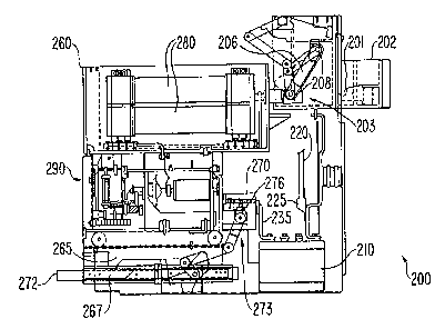
Figures 2 and 3 illustrate side and front views of a
motor controller 200 according to one embodiment of the
invention. Motor controller 200 is a medium voltage
(i.e., 2300 to 7200 volts) motor controller which can
control motors in the 50 to 5000 horsepower range. Motor
controller 200 is used to start and stop a motor and also
provides short circuit and overload protection. The
motor controller is 30 inches wide and 36 inches deep.
The height depends on, for example, whether a one-high or
two-high arrangement is employed.
Motor controller 200 includes an isolation switch
202, a drawout unit 260, a load receptacle 270, current
transformers 210, and terminals 225 for connecting
r
2144290
- 5a -
outgoing cables, or field wiring. In Figure 2 the motor
controller 200 has its isolation switch open and its load
receptacle open. In Figure 3 the drawout unit has been
removed for clarity. The outgoing cables can enter from
the top as shown in Figure 3 by solid lines 220 or can
enter from the bottom as shown in Figure 3 by dotted
lines 220a.
The isolation switch 202 is used to isolate the
motor controller 200 from the main power supply (not
shown) during maintenance on the motor controller.
Three-phase main power is fed to the controller via main
power supply terminals 201. (In Figure 2, the second and
third main
21~4~90
-6-
power supply terminals are obscured by the first main
power supply terminal.) The isolation switch is closed
during normal, i.e., non-maintenance, operations.
Drawout unit 260 includes insulated power fuses 280
and medium voltage vacuum contactor 290. Two power fuses
are provided in parallel for each of the three phases.
(In Figure 2, the second and third sets of power fuses
are obscured by the first set.) The power fuses provide
short-circuit protection and the vacuum contactor serves
to turn the motor on and off. In the vacuum contactor
electrical connection and disconnection is made within a
vacuum chamber to minimize-arc generation.
Isolation switch 202 includes a first set of bolted
pressure contacts 203 and load receptacle 270 includes a
second set of bolted pressure contacts 273. These bolted
pressure contacts rely on bolting pressure rather than
spring pressure to achieve a low electrical contact
resistance between moveable members and terminals. The
first and second sets of bolted pressure contacts are
opened to permit withdrawal of the drawout unit 260, as
will be described in further detail below.
In operation, three-phase power is fed from the main
power supply to isolation switch 202, and from isolation
switch 202 to the power fuses 280 via the first set of
bolted pressure contacts 203. The power fuses are
connected internally to the vacuum contactor 290 on the
drawout unit 260. The vacuum contactor 290 feeds power
to the load receptacle 270 via the second set of bolted
pressure contacts 273, which in turn feed primary
windings of current transformers 210 via bus links 235.
The current transformers generate a relatively small
sensing signal for monitoring purposes in their secondary
windings that is proportional to the current in the
primary windings that is being supplied to the motor.
These sensing signals can be used, for example, for
overload protection. The primary windings of the current
transformers 210 feed terminals 225, to which outgoing
cables 220 are attached.
2144290
_ 7 _
Figures 4 to 14 will be used to illustrate and
describe the improved drawout unit disconnecting and
connecting arrangement of motor controller 200. The
design of the drawout unit disconnecting and connecting
arrangement is an important aspect of this invention.
Figure 4A illustrates a top view of drawout unit 260
in its withdrawn position, and Figure 4B illustrates a
top view of isolation switch 202 when the isolation
switch is open. Figure 5 illustrates a side view of
motor controller 200 with its drawout unit 260 in the
withdrawn position, its isolation switch open, and its
load receptacle open. Figure 6 illustrates a side view
of motor controller 200 with the drawout unit inserted,
the isolation switch closed, and the load receptacle
closed. Figure 7 is an enlarged top tview of the
isolation switch, and Figures 8, 9, and 10 are enlarged
side views of the isolation switch.
Motor controller 200 provides a technique for
disconnecting and connecting the power connections to the
drawout unit which does not use springs or stabs. As
illustrated in Figures 4 and 5, moveable line terminals
250 and load terminals 240 are provided on the drawout
unit 260. Isolation switch 202, including the first set
of bolted pressure contacts 203, and load receptacle 270,
including the second set of bolted pressure contacts 273,
are located on the stationary part of the motor
controller.
When the drawout unit 260 is inserted into the motor
controller compartment, the line terminals 250 engage the
first set of bolted pressure contacts 203 in isolation
switch 202, which supplies power to the drawout unit 260.
2144290
_8_
The load terminals 240 engage the second set of bolted
pressure contacts in load receptacle 270, which in turn
feeds power to the load. As will be described in further
detail below, the moveable line terminals and the
moveable load terminals form part of the electrical
switches between the drawout unit and the stationary
portion of the controller. The first set of bolted
pressure contacts 203 and the second set of bolted
pressure contacts 273 each incorporate a pair of
conductors for each phase which clamp onto the line
terminals 250 and the load terminals 240, respectively,
of drawout unit 260.
Figures 7 to 14 illustrate the design of the first
set of bolted pressure contacts 203 in more detail. Each
of the three (one for each phase) bolted pressure
contacts is made up of a pair of switch blades 206 having
a clamping bolt 208 at each end. The bolted pressure
contacts 203 are designed such that when the drawout unit
260 is inserted, line terminals 250 move through slots
204 in the front of isolation switch 202 and become
positioned between a pair of switch blades 206.
The switch blades 206 are connected to an
arrangement of arms 207, 209, 211, and 213, which are in
turn connected to an operating arm 217 (shown in Figure
7) via a shaft 215. Operating arm 217 is connected to an
isolation switch operating handle (to be described in
further detail below with reference to Figure 19). Arms
207, 209, 211, 213 and 217 and shaft 215 are arranged so
that as the isolation switch operating handle is moved to
the closed position, arm 217 rotates shaft 215, causing
blades 206 to move clockwise (in Figure 9) to contact the
2144290
- Sa -
main power supply terminals 201 and thus close the
isolation switch. As the shaft 215 continues to rotate,
arm 207 moves clockwise (in Figure 9) to tighten one of
bolts 208 (the left bolt in Figure 9), which has a right-
hand thread, and arm 209 moves counter-clockwise (in
Figure 9) to tighten the other bolt 208 (the right bolt
in Figure 9), which has a left-hand thread. Springs 206a
bias the isolation switch in the open position, shown in
Figure 8. The design of the arms 207 and 209 are
illustrated in Figures 11 to 14. Arm 207 includes a hole
207a for a bolt 208 (the left bolt 208 in Figure 9) and
two stubs 207b and 207c. Arm 209 includes a hole 209b
for a bolt 208 (the right bolt 208 in Figure 9) and a
hole 209a for mating with stub 207b of arm 207. Stub
207c mates with arm 211.
Two arms 219 are also rigidly connected to the shaft
215. A shutter 221 is pivotally connected to the arms
219 at the ends of the arms away from the shaft. The
shutter 221 is made of an electrical insulator. As
illustrated in Figure 8, when the isolation switch 202 is
open, the shutter 221 hangs down between the main power
supply terminals 201 and switch blades 206, bolts 208,
~1~4~~0
-9-
and arms 207, 209, 211, and 213 to provide a physical
barrier between the main power supply terminals 201 and
switch blades 206, bolts 208, and arms 207, 209, 211, and
213.
The design of moveable load terminals 240 and load
receptacle 270 is similar and will be described with
reference to Figures 5 and 15. Figure 15 is an enlarged
top view of one of the second set of bolted pressure
contacts.
Load receptacle 270 is provided with three current-
carrying clamps, or bolted pressure contacts, 276. As
illustrated in Figure 15, contact 276 has a pair of clips
279 which forms a slot 277. A bolt 278 runs through the
clips 279. The bolt 278 is connected to an arm 275 so
that when the arm is rotated counter-clockwise ( in Figure
5), the bolt 278 tightens, and the clips 279 move closer
to one another to clamp onto a load terminal.
Arm 275 is in turn connected via an arm 271 to a load
receptacle operating handle 272. Handle 272 is located
in the motor controller compartment inside of the motor
controller door (not shown) and mechanically locks in the
pushed-in (load receptacle closed) position.
The procedure for inserting the drawout unit will now
be described. Before the drawout unit 260 can be
inserted, switch blades 206 and clips 279 are placed in
their spread-apart positions using the isolation switch
operating handle and the load receptacle operating
handle, respectively, to loosen bolts 208 and 278, thus
allowing the drawout unit to be inserted with minimal
effort. Mechanical interlocking, to be described below,
ensures that these conditions exist. The drawout unit
260 is then inserted.
During insertion of the drawout unit 260, the load
terminals 240 move through the slots 277 in the front of
load receptacle 270. Handle 272 is then pushed in by the
operator, which causes arm 271 to rotate arm 27~ counter-
clockwise (in Figure 5) to tighten bolts 278, which
-10-
causes clips 279 to come together and grip load terminals
240.
In the isolation switch 202, the bolts 208 are still
loose at this time and the switch blades in each pair of
switch blades are separated from each other, and the
drawout unit 260 is still isolated from the power source,
as illustrated in Figure 8. Moving the isolation switch
operating handle to the closed position causes the
following events to occur in succession in isolation
switch 202:
1. As illustrated in Figure 9, arms 219 move
counter-clockwise to lift up shutter 221. Arms 209 push
the shutter 221 away from the main power supply terminals
201 and the switch blades 206 move clockwise to contact
main power supply terminals 201 and thus close the
isolation switch. In this position, power is supplied
from main power supply terminals 201 to blades 206 and
bolts 208. However, the bolts 208 are still loose.
2. As shown in Figures 9 and 10, as the isolation
switch operating handle is moved to its fully closed
position, arm 207 moves clockwise (in Figure 9) and arm
209 moves counter-clockwise (in Figure 9) and the arms
fold down, thus tightening bolts 208 and applying contact
pressure to main power supply terminals 201 and to line
terminals 250. In this fully closed position, the switch
blades 206 are locked closed and the main power supply
tenainals 201 and the line terminals 250 of the drawout
unit 260 are securely clamped.
Figure 6 shows the motor controller 200 with the
drawout unit 260 inserted, the isolation switch 202
closed, and the load receptacle 270 closed.
Motor controller 200 has the following interlocks for
personnel safety and to prevent equipment damage:
1. A mechanical interlock prevents closing the
isolation switch 202 unless the door to the motor
controller is closed.
2 . A mechanical interlock prevents opening the door
if the isolation switch is closed.
~19~4~~a
-11-
3. The load receptacle operating handle 272 must
be pushed in before the motor controller door can be
closed.
4. An electro-mechanical interlock ensures that the
vacuum interrupters are open before the isolation switch
is opened or closed.
5. A mechanical interlock ensures that the drawout
unit cannot be inserted into the connected position if
the isolation switch is forced closed (contrary to proper
operation) while the door is open.
The combination of interlocks 1 and 3 prevents
closing isolation switch 202 unless bolts 278 have been
tightened. In addition, the motor controller also
includes windows (not shown) through which blades 206 can
be viewed to visibly confirm that the isolation switch is
open and that the blades are grounded prior to
maintenance.
This method of disconnecting and connecting the
drawout unit 260 provides several significant advantages
over conventional methods employing spring-loaded stabs.
First, the contact pressure between switch blades 206 and
line terminals 250 and between clips 279 and load
terminals 240 is not dependent on a spring. Elimination
of the stabs provides superior performance under heavy
load, high temperature, and dirty environmental
conditions. In addition, a motor controller designed in
accordance with this invention generates less heat due to
the high contact pressure achieved in the bolted pressure
contacts. Over long periods of time and with exposure to
elevated temperatures, high loads and dirt, springs can
lose their tension, resulting in a loss of contact
pressure and possibly in premature failure of the
electrical connector. In addition, periodic checking for
possibly weakened springs, which is a recommended
maintenance procedure, is not required with this improved
design. -
Another important aspect of the design of motor
controller 200 relates to its compact arrangement. As
2i44~~0
-12-
illustrated in the figures, contactor 290 is mounted
horizontally under the power fuses 280 and is as far
forward as possible. The load receptacle 270 is also
moved forward, thus providing space behind the load
receptacle 270.
With this arrangement, space is provided under the
isolation switch 202 and behind the drawout unit 260 and
the load receptacle 270 to locate the current
transformers 210 and the terminals 225 for the outgoing
field wiring 220. This arrangement also permits a direct
connection between the load receptacle 270 and the
current transformers 210 using a solid piece of metal in
the form of bus links 235, instead of using cables.
By locating the current transformers 210 and
terminals 225 for the outgoing wiring behind the drawout
unit 260, six inches of width previously required in
conventional designs is eliminated, reducing the overall
width of the controller from 36 inches to 30 inches.
This improved design thus results in an enclosure width
6 inches less than the narrowest enclosure available in
the industry, using components of a conventional size.
Because medium voltage controllers are normally installed
side by side in line-ups consisting of several to many
enclosures, the resulting savings in floor space are
considerable. Moreover, the elimination of internal
power cables that are conventionally used to connect the
contactor to current transformers provides enhanced
reliability, reduces manufacturing costs, reduces power
losses, and provides extra space for field wiring
termination.
Figures 5 and 16 illustrate other important
improvements in motor controller 200 relating to the
removal of the drawout unit 260. These figures
illustrate a side view of motor controller 200 with the
drawout unit 260 withdrawn. In Figure 16 the drawout
unit is displaced upward for clarity. -
Drawout unit 260, (including contactor 290, power
fuses 280, and other components) rests on a drawer 265
~144'~90
-13-
when the drawout unit is both inserted and withdrawn.
The drawer 265 is attached to the motor controller
housing by a pair of sliding rails 267. (From the
vantage point of Figures 5 and 16, the second set of the
pair of sliding rails is directly behind the first set
and is thus obscured.) Four guide pins 269 are provided
on top of the drawer 265 on which the drawout unit 260
sits. The pins 269 serve to position the drawout unit
260 accurately on drawer 265. Wheels 266 are provided
for wheeling the drawout unit when the drawout unit is
removed completely out of the drawer 265.
The sliding rails 267 must be capable of supporting
the drawout unit from the stationary portion of the motor
controller when the drawout unit is in the withdrawn, or
cantilevered, position and must also provide for the
precise alignment of the drawout unit with the stationary
portion of the motor controller when the drawout unit is
being inserted.
A number of suitable designs exist for sliding rails
267. Figures 17 and 18 are enlarged side and end views
of one suitable design for the sliding rails. This
design is a four-race precision ball bearing slide
manufactured by Jonathan Manufacturing Corporation
(Fullerton, California). The slide is approximately 33
inches long, 2 inches high, and ~ inch wide and consists
of three elongated sections 267a, 267b, and 267c.
Section 267a is attached to the stationary portion of the
motor controller and section 267c is attached to drawer
265. Ball bearings 268 in four races formed by adjacent
sections facilitate movement of the sections with respect
to one another.
When the drawout unit 260 is inserted, accurate
movement of the drawer 265 along sliding rails 267
results in proper mating of the line and load terminals
250 and 240 with the first and second sets of bolted
pressure contacts 203 and 273, respectively, and results
in proper operation of the interlocks.
2~44~90
-14-
This technique of supporting and guiding the drawout
unit provides significant advantages over the
conventional method of employing wheels rolling along a
guide track. The accurate movement of the sliding rails
provides precise alignment between the drawout unit and
the fixed mating components. In addition, the drawer
serves as a service platform for controllers mounted in
the upper compartments of two and three-high
arrangements. In contrast, conventional drawout units
require a separate temporary service platform in these
applications.
Figure 19 is an overall view of a two-high motor
controller arrangement 1000 constructed in accordance
with this invention, with the doors and other components
omitted for clarity. Motor controller arrangement 1000
includes two motor controllers in a common housing 900.
In Figure 19, the drawout unit 360 of the lower motor
controller 300 is shown in the withdrawn position,
supported by drawer 365, and the drawout unit 460 of the
upper motor controller 400 is shown in the inserted
position, supported by drawer 465. A middle compartment
500 is used to house low voltage components, for example,
protection relays. Figure 19 also illustrates isolation
switch operating handles 317a and 417a.
Although the invention has been described above with
reference to certain specific implementations of the
invention, the invention is not limited to the specific
implementations described above. Numerous variations of
the invention will occur to those skilled in the field of
motor controller design after receiving the above
teachings. Therefore, the scope of the invention is
defined by reference to the following claims.