Note: Descriptions are shown in the official language in which they were submitted.
WO 94/06008
PCT/US93/08546
1
PIT DETECTOR AND METHOD
Technical Field
This invention relates generally to the field of detecting
pits in fruit and more particularly to a method and apparatus
for the non-destructive inspection of small fruit such as
cherries and olives in order to confirm that the pit has in
fact been removed therefrom.
~ackaround Art
The problem of ensuring that pits have been removed from
cherries has long been a priority for the cherry producing
industry. Over 95 per cent of the tart cherry crop is pitted
and processed into canned, frozen and dried fruit, or made
into juice. In accordance with United States Department of
Agriculture procedures, pitted cherries are separated into
grades . Grade A cherries may not contain more than one pit
per 2.5 pounds of finished cherries. Thus, it follows that
if cherries are determined to be "Grade A" the producer has a
more valuable product which commands a higher price. In
addition, producer liability for impure products has recently
become an issue given the potential for broken teeth, etc.
when served as part of a meal in a pie, topping and the like.
For the foregoing reasons, the cherry producers have set a
goal of not more than one pit per 62.4 pounds of finished
product.
In an effort to produce a finished cherry product with
fewer pits, a number of devices have been produced which
inspect the cherry after it has allegedly been pitted in an
attempt to ensure pit removal. U.S. patent No. 4,666,045 to
WO 94/06008 ~ '~ ~ ~ ~ ~~ PCT/US93/08546
2
Gillespie et al. discloses one such apparatus and a method
for detecting pits in cherries. Specifically, the patent
teaches an optical pit detecting device comprising an
inspection zone and a scanning beam generator that sweeps a
transmission scanning beam across the inspection zone. An '
array of sensors are positio~ied on the opposite side of the
inspection zone and produce a series of sensor signals that
are proportional to the received light intensity based on the
amount of light transmitted through the cherry. A second
sizing beam generator generates a signal representative of
the optical path length through which the transmission
scanning beam travels within the fruit and generates a signal
that is proportional to the size of the fruit. The two
signals are then analyzed to determine the presence or
absence of a pit within the yruit.
Another method and apparatus for detecting pits in fruit
was disclosed in U.S. Patent No. 5,077,477 to Stroman et al.
The device comprised a U-shaped "inspection zone" in which a
first side includes a linear array of infrared light emitting
diodes and an adjacent linear array of infrared light
sensors. Similarly, the opposite side of the inspection zone
includes an array of sensors and an adjacent array of
infrared light transmitting diodes that are adapted to
receive/send signal from the opposite side of the inspection
zone. Also provided for each of the foregoing is means for
collimating the emitted light as well as a filter for
reducing the ambient and scattered light on each of the
sensors. The foregoing take the form of an aperture Which
has a smaller diameter than the size of the corresponding
WO 94/06008 PCT/US93/08546
3
sensor/emitter. The apparatus measures both the transmitted
and reflected light and utilizes an algorithm based on both
of the foregoing to determine the presence or absence of a
pit or pit fragment. This apparatus is not preferred since
the diode characteristics shift relative to each other over
time which degrades performance and frequent calibration is
therefore required.
The potential methods as well as what is believed to be
the state of the art for detecting pits in cherries is
thoroughly discussed in the article entitled °'Potential
Methods for Detecting Pits in Tart Cherries", by E.J. Timm
et al, which appeared in the January 1991 issue of Applied
Engineering in Agriculture (Vol. 7(1) air pages 103-109)
published by the American Society of Agricultural Engineers,
S. Joseph, MI 49085-9659. The reader is referred thereto for
an in depth discussion of the current state of the art of
detecting pits in cherries.
To date,. none of the known pit detectors have been widely
adopted. It is believed that this is due to a number of
factors including fruit deformation, high equipment cost,
unacceptable error rates, machine speeds that are
uneconomical and frequent detector down time due to component
failure or the necessity for cleaning.
In view of the foregoing, it is therefore an object of the
present invention to provide an improved method and apparatus
for the detection of pits that meets or exceeds the industry
set goal of not more than one pit per 62.4 pounds of
cherries.
CA 02144335 2003-03-06
'73092-5
4
Another object: of the present irmention is to
provide an improved method and a~>paratus °=or the detection
of pits that permits norr-destructive inspection and thus
does not deform the fruit .
Another object. of the present irnvention is to
provide am improved method ar:,d apparatus 1_or the detection
of pits that is reliable..
Yet another ox_~j ec:t of the present invention is to
provide an improved method ar~.d apparatus for t:he detection
of pits that inspects the product at a high rate of speed.
Still another object of the present invention is
to provide an improved n~:ethod arid apparatus for the
detection of pits that i.s economica.l.
Summa~.~-of the Invention
In accordance with the present invention there is
provided a method and apparatus for detecting the presence
of a pit other foreign substance present within an object as
such as a stone fruit as it passes thraugt= an inspection
zone. The apparatus comprises a point source light emitting
means such as an infrared light emitting diode positioned on
one side of the inspection zone and adapted to transmit: a
single light beam across the inspection zone. Means for
generating a signal that is proportional to the intensity of
the light transmit:ted through t.lze fruit as the fruit passes
through the inspection zone positioned ors the opposite side
of the inspection zone and additionally including means for
collimating the light beam po~it~.ioned i~etween the light
source and the means foz° generating a signca:l. proximate the
means for generating a signal.
CA 02144335 2003-03-06
'73092-5
In accordance with the method, fruit is inspected
<rs it passes through an inspection zone. An infrared point
light source is transmitted across the inspection zone
through the fruit. The light. beam is traxusmitted through
5 the fruit and is collimated by passing it. through a slit
7_ens. The light beam is then passed through an infrared
f_i:lter positioned beriinc~i the filter and :is imaged on to a
1_inear CCD sensor. The linear CCD sensor then produces an
output signal in the form of a plurality c::>f output voltage
~;ignals that are proport:_ional. to the intensity of th.e light
imaged on to the linear CC:D sensor at Eacr~ point along its
length. The output voltage signals are tl-xen converted into
digital data representative thereof. The cherry is
,canned a plurality of times to generate a.~ data set matrix
and the intensity variations within the data set matrix are
analyzed too determine the presence o:r abse,nce of a pit .
According to a broad aspect of the invention there
is an apparatus for detecting the presence of a pit within a
fruit, passing through an inspection zone and comprising:
a) a point source light emitting means positioned on one
side of the inspection zone and adapted to transmit a single
light beam across the inspection zone; b) means for
generating a signal that:. is proportional. to the intensity of
the light transmitted through the fruit as the fruit passes
through the inspection zone positioned on the opposite side
of the inspection zone; and c) means for collimating said
light beam positioned between said poirzt~ light source and
the means for generating a signal, said means for
collimating said light beam being po si.t: ior.r.ed proximate said
means for generating a signal; whereby as the fruit passes
through the inspection zone and is illuminated by the light
source and. the intensity of the Light:. transmitted through
the fruit is received by the means for generating a signal,
CA 02144335 2003-03-06
'3092-5
5a
a two dimensional analyzable bit map representative of the
cross-sectional density is pxoduc~ed.
According to a.~ second broad aspE::~ct of the
invention there is an apparatus far detect::ing the presence
c>f a foreign substance within a substantially spherical
abject passing through an :inspect.ian zone and comprising:
a) an infrared point source light. emitting means positioned
cm one side of the inspection zone and adapted to transmit a
shingle light beam acros:~ the :inspect:ion :~c~ne; b) a linear
C'CD array for generating a signal that is proportional to
the intensity of the light transmitted through the object as
the object: passes through t:he inspectic.>n none; c) a slit
lens for collimating the light beam on the linear CCD array
in alignment therewith, said slit lens being positioned
proximate said linear CCD array an t~~ie ~:~pf:,as:ite side of the
inspection zone between the linear CCD arx-ay; and d) an
infrared falter in a:ligrnment wit:.h and between said slit. lens
and said linear CCD array; whereby as r_ze abject passes
through the inspection zone and is illuminated by the
infrared light source and the intens:ity~ of the light
transmitted through the object is received by t:he linear CCD
array, a two dimensional analyzable bit map representative
of the crass-section of they object's dens~.ty is produced.
According to another brand aspect of the invention
there is a. method of inspecting a stone fruit passing
through an inspection zone comprising the steps of:
a) transmitting an infrared pairnt source L ir~ht beam across
the inspection zone; b) colliEnat~incr t:he light beam by
passing it through a slit lens; c) f~..i.r_ering the light beam
by passing it through an. infrared :Ei~l.ter positioned behind
the slit lens; d) imaging the light beam on to a linear CCD
sensor positioned behind the filter; e) groducing an output
signal in the farm of a oluralit:y of nut=:put vo1_tage signals
CA 02144335 2003-03-06
'73092-5
5k>
that are proportional to the intensity of the light imaged
c>n the linear CCD sensox- at:. each point a:L~::~ng its length.
According to a further broad ask:~ect of the
invention there is a method of inspecting a substantially
~~pherical object passing through an inspection zone for the
presence of a foreign sL~bst:ar~ce c:omprisinck the steps of
(a) transmitting a point source light beam across the
inspection zone; (b) collimating the light by passing it
through a slit lens; (c) imaging the light.: beam on to a
linear photosensitive receiver positioned behind the slit
lens; (d) producing an output signal from the linear
photosensitive receiver in the form of a plurality of output
voltage signals that are proportional to t:he intensity of
the light imaged on to the linear 'photosensitive receiver at
each point along :its len.gti~.
Brief description of the dx°awinqs
Additional objects and features of this invention
will become apparent from the following detailed description
cf the invention, and from the accompanying drawings, in
which --
Figure 1 is a perspective view a~f the pit
detection apparatus according to the present invention and
illustrating schematically, a stone fruit passing through
the inspection zone of t:he detec::tor.
WO 94/06008 PCT/US93/08546
6
Figure 2 is an exploded schematic view of the pit
detection apparatus according to the present invention and
illustrating the infrared light source on one side of the
inspection zone and the detector assembly positioned on the
opposite side of the inspection zone. '
Figure 3 is a schematic view of the desired collimation of
the light source as it passes through a cherry so that a
clear image of the cherry is projected on to a focal plane
for analysis.
Figure 4 is a schematic view of a cherry as a convex lens
on one side and a concave lens on the opposite side.
Figure 5 is a schematic view of a beam of light emanating
from a point source passing through the front half of a cherry
and becoming collimated and then passing through the back half
of the cherry and being uncollimated by the lens action.
Figure 6 is a schematic view of a beam of light emanating
from a point source passing through the front half of a cherry
and becoming collimated and then passing through the back
half of the cherry and further illustrating the corrective
lens according to the present invention that recollimates the
beam so that it focuses on the focal plane.
Figure 7 is a schematic plan view of how the slit lens in
the present invention acts to collimate the beam so that it
focuses on the focal plane.
Figure 8 is a front view of the focal plane according to
the present invention and illustrating the bit pattern
representative of a cherry containing a pit that is created
for analysis after the cherry has traversed the inspection
zone.
WO 94/06008 ~ PCT/US93/08546
7
Figure 9 is a block diagram of the circuitry employed
according to the present invention that captures the bit
pattern of the cherry as it traverses the inspection zone for
analysis to determine the presence or absence of a pit.
Detailed Description of the Illustrated Embodiment
While the present invention will be described more fully
hereinafter with reference to the accompanying drawings in
which a particular embodiment is shown, it is to be
understood at the outset that persons skilled in the art may
modify the invention hereindescribed while still achieving
the favorable results of the invention. Accordingly, the
description which follows is to be understood as a broad
teaching disclosure directed to persons of ski'!1 in the
appropriate arts and not as limiting upon the present
invention.
It will be understood at the outset that the present
invention is broadly directed to an inspection station for
the inspection of obiects moving through an inspection zone.
The invention was conceived for the inspection of stone fruit
such as olives, plums, peaches, and in particular for the
inspection of cherries in order to determine whether the pit
has been removed therefrom. Therefore, in the specification
which follows, the invention is described with particular
reference to cherries, but the reader will note its utility as
an inspection station in the broad sense.
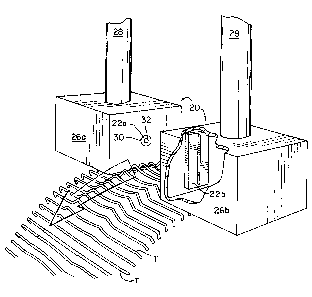
Referring now to the drawings and in particular to figures
' 1 and 2, the pit detecting apparatus 20 of the present
WO 94/06008 ~ . PGT/US93/08546
8
invention is there illustrated. In figure 1, a cherry is
schematically illustrated by the arrow as moving through a
sensor comprising a transmitter 22a and a receiver 22b, the
space therebetween defining an inspection zone 24. Also shown
is a segment of a moving track T upon which the cherries rest '
and that moves the cherries in single file through the
inspection zone. Sensors 22a and 22b is positioned within
housings 26a,b which are supported from above by hollow rods
28 which are connected to a support (not shown).
Housing 26a defines a cavity and a hole defining an
opening 30 which faces the inspection zone. Positioned
within opening 30 is a point source light emitting means 32
which in the illustrated embodiment is an infrared light
emitting diode (LED) that is adapted to transmit a single
beam of light across the inspection zone. The LED also
includes terminals (not shown) which are connected to a power
source located remote from the LED. The point light source
emitting means 32 may also be a tightly clustered diode array
substantially emulating a point light source.
It will be noted that for the inspection ~of fruit,
infrared light is preferred, however, the reader will note
that for scanning objects of other densities, light of
different frequencies may be required for effective
penetration. In addition, certain objects may require light
of a higher intensity than can be provided by a single diode.
Therefore, the intensity can be increased by providing a
number of diodes clustered together so as to emulate a point
source, the significance of which will be better understood
as the specification proceeds.
WO 94/06008 ~ ~ ~ PCT/US93/08546
9
Housing 26b is positioned on the opposite side of the
inspection zone and defines a cavity. The housing includes a
means for focusing the light beam or a slit lens 40 in the
form of an elongate slit in the wall of housing 26b
positioned directly across the inspection zone from the light
source 32. Within housing 26b behind slit lens 40 is an
infrared filter 42. Located behind the infrared filter 42
and in linear alignment with both slit lens 40 and filter 42
is a means 44 for generating a signal that is proportional to
the intensity of the light transmitted through the cherry.
In the preferred embodiment the means for generating a
proportional signal 44 takes the form of a linear
photosensitive receiver such as a linear CCD device as is
commonly found in facsimile or "fax" machines, or photodiode
array. One such device is the TCD 133 manufactured by
Toshiba which produces a 2048 x 1 bit output signal in the
form of a serial voltage signal on line 46. The circuitry
required to drive CCD sensor 44 is well known to persons
skilled in the art and a detailed discussion is not deemed
necessary. Therefore, it is shown schematically as being
attached to circuit board 48.
The input section of the pit detector having just been
described, it will be helpful to the reader to understand the
theory of operation of the apparatus. Referring now to
figure 3, a cherry C is depicted as being in the optical path
of light source 32 and in order to accurately detect the
presence/absence of a pit, a shadow as illustrated on focal
plane 44 must be created. As illustrated in figure 3, the
front half of the cherry itself may be viewed as a convex lens
WO 94/06008 PGT/US93/08546
that acts to collimate a diverging beam emanating from the
point source. A collimated beam is precisely what is
required in order to image the cherry pit clearly onto focal
plane 44 in order to capture the transmitted light for
analysis of the relative intensities thereof. The density
variations that occur directly correlate with the presence or
absence of a pit or other foreign substance. However, as the
cherry is substantially spherical, the second or back half
thereof acts to bend the light back towards a point source,
thus collapsing the image prior to its reaching the focal
plane 44. This phenomenon is illustrated in figure 4 wherein
the cherry C is shown as a sphere and schematically as a pair
of lenses on each side of a central slice having parallel
sides (substantially without light bending qualities). The
effect of the lens system that is described in figure 4 is
illustrated in figure 5. The IR light emanates from the IR
point source 32, passes through the front portion of the
cherry which collimates the beam. But as the light passes
through the back half of the cherry, the light is bent back
towards a point which collapses the image back to a point
source on to focal plane 44.
Thus, it will be seen that in order to produce a system
that images a cherry on to a remote focal plane must not
allow the transmitted light to converge (figure 6).
Specifically, figure 6 illustrates schematically the present
system which prevents convergence of the transmitted light.
As previously mentioned, the cherry acts to collimate and then
refract the light beam back towards a point source as it
passes through the cherry. An additional lens must,
WO 94/06008
PCT/US93/08546
11
therefore, be provided which cancels the tendency of the back
half of the cherry to refract the light beam back to a point
source on the focal plane 44. This lens is schematically
illustrated in figure 6 by the lens adjacent the focal plane
44 and in the illustrated embodiment comprises a slit lens.
Those knowledgeable in the art of optics will recognize that
the slit lens operates on essentially the same principals as
the "pin-hole" camera. Specifically, as the cherry moves
through the field of view of the slit only rays perpendicular
to the focal plane are permitted to pass through the slit and
illuminate the sensor. This action dynamically simulates
recollimation of the image as illustrated in figure 6. The
deep depth of field provided by the slit lens essentially
eliminates the need for any type of active focusing system
which would have been required to compensate for variations in
cherry size and shape.
In operation, the cherry is moved via track T between the
infrared light source 32 positioned in housing 26a and the
receiving sensor 22b positioned in housing 26b. As the
cherry is moved through the inspection zone, the light beam
from the infrared diode 32 penetrates the cherry and the CCD
44 is pulsed every 4 milliseconds so as to obtain a plurality
of vertical "slices" of the cherry which are output on line
46 and each of which contains 2048 separate elements
representative of the intensity of light transmitted through
the cherry. Thus, the intensity of the received light when a
pit is present will be lower then when passing only through
the fruit. This series of output voltages on line 46 is then
input to a video amplifier 48 in order to amplify the signal
WO 94/06008 ~, ~" ~ ~ PCT/US93/08546
12
to a level where it can be input into analog to digital
converter 52 which produces an 8 bit output signal on line 54
which is then put to a computing means 56 such as a single
board image processor and is stored in a buffer therein (not
illustrated). The stored image is similar to that
illustrated in figure 8 where the darker data points
represent higher output voltages from the analog to digital
converter and represent the portion of the cherry containing
the higher density pit. The digital data is then analyzed by
the image processing means or image processor 56 in order to
determine the presence or absence of a pit. The algorithms
are not discussed here as they are well known to those skilled
in the art. Furthermore, as the quality of the stored data
representative of the relative density across the cherry
improves, the ~.ccuracy of detection improves proportionately.
The foregoing embodiments and examples are to be
considered illustrative, rather than restrictive of the
invention, and those modifications which come within the
meaning and range of equivalence of the claims are to be
included therein.